Basement Construction in Ho Chi Minh Pitfalls and Collected Stories
|
|
|
- Edwina Hopkins
- 5 years ago
- Views:
Transcription

1 Basement Construction in Ho Chi Minh Pitfalls and Collected Stories


2 HCMC Typical Ground Conditions Soft soils to significant depth Soft clays, loose sands Typically 10 defined strata with sand density and clay stiffness increasing at depth Bedrock at -130 to -200m Footnote: where the water content is greater than the liquid limit these soils are virtually one stage from being fluid Reference: Journal of Civil Engineering Paper by Nguyen Kiet Hung and N. Phienwej, August 2014.

 may directly affect deep")
3 Aquifers 5 no. Aquifers in HCMC area 2 no. upper aquifers (Holecene and Pleistocene) may directly affect deep excavations Clay aquitard between these two aquifers


4 Site Retention Wall Types 4 main types in HCMC Dependent on the soils and excavation depth 2 basements or more: D-wall likely


5 Substructure Semi Top-Down Construction Stage 1 : Diaphragm Wall and Piles are installed into the ground. King posts are provided at each column/pile location. Stage 2 : Ground floor slab is constructed first, leaving opening for excavation Stage 3 : Excavation is carried out simultaneously with basement construction Stage 4 : Basement floors completed and pile cap completed prior to commencement of superstructure Stage 5 : Superstructure is constructed on completion of the basement

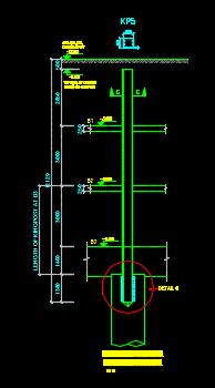
6 Kingpost Options

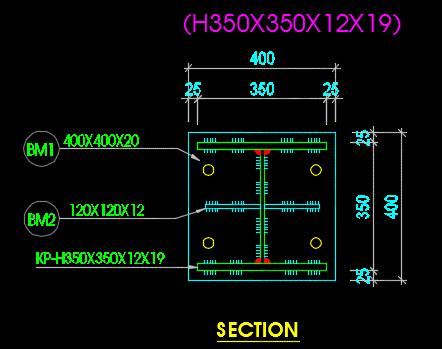
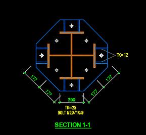
7 Kingpost Options
 Within 30min (!")
8 Case 1: City Centre - May level basement; 21 storey building 20m deep excavation 1m thick, 45m deep D-wall Large void in D-wall: 350mm x 1700mm at -21m Severe water ingress could not be controlled (water head 18.5m) Within 30min (!), excessive subsidence occurred, severe damage to 2 storey building Remedial measure jet-grouted piles

9 Case 2: City Centre January level basement; 40-storey building 19.8m deep excavation m thick, 27m deep D-wall Existing 600mm, 10m deep d-wall in two corners Existing d-wall integrated into new d-wall During excavation at -11m, structural failure at interface of new/old d-wall Severe water ingress 2 adjacent 2-storey buildings collapsed; 9 townhouses severely damaged. Remedial measures jet-grouted piles
 During excavation of 3 rd basement at -11m, structural failure of d-wall at interface of")
10 Case 3: City Centre April level basement; 37-storey building 14.0m deep excavation; 0.8m thick, 35m deep D-wall Existing 600mm, 12m deep d-wall in two completed (for earlier 1-level basement) During excavation of 3 rd basement at -11m, structural failure of d-wall at interface of new/old d-wall Poor interface between new and original D-wall panels large ingress of groundwater and sandy soil Subsidence caused damage to adjacent building. After almost 1 year delay, jet grouting, and needle grouting sealed the leaks

11 Case 4: District 7 2 basement levels with - 9m-11.5m deep excavation Contiguous pile wall has been installed with the lateral support from temporary steel strutting Bottom-up construction Failure of the steel strutting system Collapse of the contig wall and damage to adjacent buildings
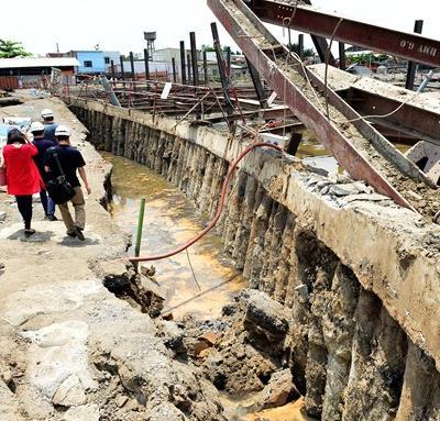

12 Case 4 (continued )
 Failure of sheet piled wall due to failure of strutting")
13 Case 5: District 8 June basement levels with - 9m deep excavation bottom-up construction Steel sheet-piles with lateral support from steel strutting system Excessive adjacent ground settlement ( mm) Failure of sheet piled wall due to failure of strutting system
")


14 Case 5 (continued ) Observed settlement of the adjacent walkway is about 20 to 40 cm

15 Case 6: District 7 December basement levels with - 9m-11.5m deep excavation Bottom-up construction Steel sheet-piles with lateral support from steel strutting system Failure of steel strutting system leading to collapse of the sheet piling

16 Case 7: District 7 2 basement levels with -9m-11.5m deep excavation Very thick sand layer situates below the ground level Bottom-up construction D-wall with lateral support from steel strutting system The sand boiling due to short D-wall. Inadequate water level management.
17 Current Vulnerabilities Lateral displacement > 50mm SI focus on foundation parameters Heave of the excavation base Reliability of the FEA (Plaxis) Lack of guidelines/regulations Lack of instrumentation Lack of dilapidation surveys
 Use of ground improvement (eg. jet grouting) Cost vs Risk.")
18 Prevention Reduction of wall deflections during excavation Clear authority guidelines Selection of wall type and bracing method (D-wall with top-down construction in city centres) DW embedded into impermeable layer (or if not practical, lowering the ground water table) Use of ground improvement (eg. jet grouting) Cost vs Risk.! Selection of appropriate soil parameters (especially soil stiffness of soft clay)


19 CDM Ground Improvement Option 1 CDM Soil/Cement columns

20 Grouting Work for Soil Improvement Option 2 Jet Grouting Injection of grouting mixture in soil at high pressure to form grouting piles
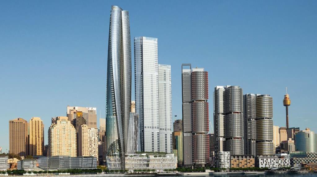
21 BARANGAROO: BASEMENTS

22 BARANGAROO SOUTH Developer: Lend Lease Project Location: Adjacent to Hickson Road, Sydney, NSW 2000 Project Value: $6 billion Diaphragm wall D&C contractor: Mernard Bachy Diaphragm wall designers: MB/ Coffey/ Calibre Consulting Geotechnical Consultant: Coffey Piling Contractor: Bauer/AFS 22 BARANGAROO SOUTH

23 GEOLOGY 23 BARANGAROO SOUTH
24 DIAPHRAGM WALL SOLUTIONS & CHALLENGES Short wall above basement level Anchors avoiding future piles + D-wall crossing future tunnels No inclined anchors due to existing basement Crossing existing caissons Anchors avoiding future piles D-wall crossing future tunnels Anchors avoiding existing caissons 24 BARANGAROO SOUTH
25 BASEMENT General depth of basement up to 9m - 12m Depth of wall from, 4.0m to m Typical wall thickness 0.8m to 1.2m, Panel lengths from 3.4m to 7.8m Groundwater cut-off achieved economically with 0.3m embedment into rock Inclined External Rock Anchors, East, West and Northern Boundaries Vertical anchors adjacent to Macquarie Bank Open Excavation 30m 7.5m 25 BARANGAROO SOUTH
26 DIAPHRAGM WALL SOLUTIONS Adjacent to Western Caisson 26 BARANGAROO SOUTH
27 DIAPHRAGM WALL SOLUTIONS Existing Basements 27 BARANGAROO SOUTH


28 28 BARANGAROO SOUTH