SystemFS. SystemFS product sheet. Generation 6
|
|
|
- Amice Cox
- 5 years ago
- Views:
Transcription
 10 year guarantee (optional 20 years) FS Gen6 - Enhanced version of FS Gen5 Fewer screws Optimized deployment of materials Improved")


1 SystemFS Generation 6 No ground sealing Extremely short mounting time Maximum level of pre-fabrication Optimally aligned system components High durability due to optimal material combinations Best possible accessibility for terrain maintenance (central support) 10 year guarantee (optional 20 years) FS Gen6 - Enhanced version of FS Gen5 Fewer screws Optimized deployment of materials Improved adjustment options Effort for planning and mounting is significantly reduced through the use of GPS-technology. The FS open area mounting system has been deployed by Schletter for many years, in a large number of projects across Germany and Europe. Project-specific structural analyses and optimal use of materials take into account the ever increasing pressure of costs, particularly in the area of open area systems. Structural safety verifications are carried out consistently and without compromise according to the current level of standardization. Experience leveraged from numerous projects achieving two-digit MW capacity has been assimilated into the 6th generation FS-System along with a consistent level of enhancement of the entire construction, based upon simulation calculations. All potential for in-house prefabrication is utilized to optimize mounting time on the construction site. 1 / 8


2 System characteristics The first step to generating a competent site plant is to perform a soil survey on location. Within the framework of this survey, numerous tests are carried out and soil samples are taken to determine the ground profile and structure, the determining factors of the quantitative loadbearing capacity of the ground: Inclined pull tests Horizontal pressure tests Creation of soil profiles Chemical analysis in a laboratory Mechanical background inclined pull tests Inclined pull tests use the principle that wind does not simply enact forces in the vertical or horizontal direction, but induces almost a perpendicular force on the module surface. A surface pressure is thus created from the application of the bending moment in the form of a force couple. With inclinations in excess of 15, the frictional resistance between the pile and the surrounding ground is generally higher than the jacket friction which results in a greater pull resistance. Hot-dip galvanized pile-driven profiles in different size categories are used for the foundation. The custom-developed ram form ensures optimal anchoring in the ground with maximum flexural rigidity. The anchoring forces can also be transmitted as far as the upper connection point, thus ensuring optimal structural safety of the plant and protection against wind and snow loads. The anchoring of the pile driven profiles in the ground is carried out by means of special terrain-friendly hydraulic pile drivers. This pile driving technique is particularly suited to large plants. Depending on the given terrain, a performance of about 250 piles per day can be achieved. Work on difficult types of terrain (stones, etc.) is also possible; With the presence of bedrock, for example, the machine may also be equipped with a drilling device. Mounting on slopes is also possible. The structural base of each FS-plant is the optimized support geometry. Depending on the desired module rack size, either a single support or a stanchion support is used. But principally a single support base that optimally utilizes the structural characteristics of the ground anchoring and the appropriate load-bearing capacity under moment loading. By deploying a continuous profile as far as the attachment head, additional joints (with the associated mechanical effort and / or risk of corrosion) is avoided. A reduced number of components and almost 100% in-house prefabrication of the complete support geometry make for extremely short mounting times. 2 / 8


3 Experience from numerous open-area projects has led, in the case of the open area FS system, to a new support geometry which can be largely prefabricated in-house and can be mounted quickly and safely on the construction site. This saves valuable time on site and enables high quality daily performance! Fix the attachment head at the foundation Unfold the support, set it in position, secure the lower strut Insert the locking plate at the head attachment - that s it! Designated clamp types are available for all module types, particularly for the extremely fragile thin-layer module. Experience in the clamping of thin-layer modules has been gained from a great number of project implementations. We work in close cooperation with manufacturers of thin-film modules and perform structural FEM-simulations in order to optimize the clamping geometry. The cross beam always presents a profile geometry that is aligned to the flow of forces (Schletter utility model protection). Thus, the required structural characteristics are achieved with minimum utilization of materials. Mounting grooves are incorporated into all profiles to facilitate assembly. The cross beams are fastened to the supporting units by means of special mounting claws Module mounting is carried out quickly and cost effectively from the ground, or, depending on the module arrangement, using appropriate auxiliary devices. Framed modules are usually mounted vertically above each other, unframed thin-film modules horizontally above each other, in order to leverage from the structural characteristics of the respective module types. 3 / 8


.")


4 The range of components is completed by accessory parts for simplified mounting: Cable duct Cable clip for purlin Cable clip for girder Pipe clamp for foundation On request, the complete plant can be equipped with exterior lightning protection by means of only a few additional components. Schletter GmbH offers a special planning program to this end (please refer also to the FS protect product sheet). Time is money! Due to structural guidelines and raw material costs, a reduction of the so-called BOS-cost (balance of system) in the mechanical sector is only possible by a considerable reduction of the mounting time on the construction site. The mounting systems FS, Generation 6, are therefore pre-mounted in the factory to 100% and are delivered to the building site just in time. 4 / 8
5 Technical data Material Fastening elements, bolts: High-grade steel Profiles: Aluminium MgSi05 /EN AW 6063, EN AW 6005 Pile-driven foundations: Steel, hot-dip galvanized Long service life, high residual value, no disposal costs Easy plant-re-powering due to modular design Logistics Quick and easy mounting Maximum level of pre-assembly Optimized delivery to the construction site Construction Adjustment options to compensate for uneven ground Cost-optimized complete construction based on structural optimization For framed and unframed modules Accessories Cable channels, cable ducts Lightning protection system (FSProtect system) Components for internal potential equalization Clamps for different module types Fastening systems for large-surface laminate modules (System OptiBond) Structural analysis Structural analysis of the respective terrain based upon a geological survey Individual systems analysis based on regional load values Load assumptions according to DIN 1055, part 4 (03/2006), part 5 (06/2005), part 100 (03/2001), Eurocode 1 (06/2002), DIN 4113, DIN 18800, Eurocode 9 and further or corresponding national norms Optimized profile geometries with highly efficient material utilization Verification of all construction components based on FEM-calculation Vibration simulations regarding wind loads, optional Earthquake simulation optional Delivery and services Terrain maintenance Lightning protection earthing potential equalization Guarantee and Certifications Ground survey and structural analysis Structural analysis of the individual rack based on regional data Pile driving of the foundations and delivery of the complete mounting material optional: Rack mounting optional: Complete module assembly Optimum terrain maintenance due to central support Sheep grazing Possible extension with outward lightning protection systems Components for the internal potential equalization Potential equalization certified acc. to VDE 0100, part / 8


6 Project planning examples FS 3H 3 modules, horizontal arrangement especially for unframed thin-film modules FS 4H 4 modules, horizontal arrangement especially for unframed thin-film modules FS 5H 5 modules, horizontal arrangement especially for unframed thin-film modules 6 / 8


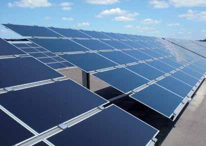
7 FS 6H 6 modules, horizontal arrangement especially for unframed thin-film modules Economic efficiency - also at locations with high wind loads FS 2V 2 modules, vertical arrangement Optimal with framed modules Typical arrangement for crystalline module designs Typical module 1.6. to 2m FSVario 1V 1 module, vertical arrangement Special design FSVario Yield optimization by seasonal adjustment of the elevation angle Typical for 1 module row 7 / 8


8 References Please refer to our specific documentation FS reference list for more information on the reference sites. Schletter GmbH, 2012, I400042GB, V2 8 / 8