Wind uplift testing on the Click Fit PV mounting system to MCS012. Prepared for: Gary Bowden Cleaner Air Solutions UK Ltd.
|
|
|
- Suzanna Reed
- 5 years ago
- Views:
Transcription

1 Wind uplift testing on the Click Fit PV mounting system to MCS012 Prepared for: Gary Bowden Cleaner Air Solutions UK Ltd 4 th October 2010
2 Prepared by Name Dr P Blackmore Position Associate Director, Building Technology Group Signature Approved on behalf of BRE Name Mr D Richardson Position Director, Building Technology Group Date 4 th October 2010 Signature BRE Garston WD25 9XX T + 44 (0) F + 44 (0) E enquiries@bre.co.uk This report may only be distributed in its entirety and in accordance with the terms and conditions of the contract. Test results relate only to the items tested. BRE has no responsibility for the design, materials, workmanship or performance of the product or items tested. This report does not constitute an approval, certification or endorsement of the product tested. This report is made on behalf of BRE. By receiving the report and action on it, the client or any third party relying on it accepts that no individual is personally liable in contract, tort or breach of statutory duty (including negligence). Page 2 of 18
3 Contents 1 Introduction 4 2 Details of the test specimens and installation 5 3 Details of the tests carried out 6 4 Test results Click Fit hooks at 400mm centres Click Fit hooks at 600mm centres 14 5 Summary 15 5 References 16 Page 3 of 18
4 1 Introduction This report describes testing carried out on the Click Fit PV mounting system for pitch roofs to the draft MCS 012 test method for wind uplift [1]. The MCS012 draft standard specifies the test procedures which shall be used to demonstrate the performance of PV modules and solar thermal collectors and/or their installation kits under the action of: Wind loads resistance to wind uplift forces. Fire resistance to external fire Rainfall and wind driven rain weather-tightness. These test methods apply to in roof and above roof systems fixed to pitched roofs. They do not apply to systems mounted inclined above flat roofs or mounted on vertical walls. This report describes wind uplift tests. Page 4 of 18
5 2 Details of the test specimens and installation The following modules and fixings were supplied for these tests: Sharp NU180 Modules Aluminium fixing rails, part number , manufactured by xxx Click Fit roof hooks, size, material, manufactured by xxx End clamp, part number , manufactured by xxx Module clamp, part number , manufactured by xxx The size of the Sharp PV modules was 1318mm x 994mm. The Click Fit system was installed over Marley Modern flat interlocking concrete tiles by Cleaner Air Solutions staff on the BRE test rig according to the manufacturer s recommendations, see Annex A. The Click Fix hooks were installed at nominally 400mm centres for the main tests with a single supplementary test carried out with the hooks at 600mm centres. The tests were carried out using two PV modules, both of which were loaded during the testing, Page 5 of 18
![3 Details of the tests carried out The recommended test method in MCS012 for wind uplift testing is based on BS EN 14437:2004 [2], which is a](/docs-images/87/95031697/images/6-1.jpg "test method originally designed for test wind uplift resistance of roof tiles and slates (other test methods are allowed where these can be shown")

6 3 Details of the tests carried out The recommended test method in MCS012 for wind uplift testing is based on BS EN 14437:2004 [2], which is a test method originally designed for test wind uplift resistance of roof tiles and slates (other test methods are allowed where these can be shown to give equivalent or conservative results). The tests are carried out on a simulated roof structure comprising rafters at a roof pitch of 45º. Figure 1 shows the BRE test rig with a test specimen in place. Figure 1 General view of the BRE test rig with the Click Fit system in place Page 6 of 18
7 The test products are laid on the test rig as they would be installed in practice on a roof. Pneumatic rams with suction cups were attached to each of the PV modules to apply a force which simulates wind uplift loads. The test requirements are given below: Where the flashing or sealing kits provides any uplift resistance then these should be included in the test. The roof pitch shall be 45deg +/- 2 degrees. A minimum of one solar panel should be tested and the test shall be repeated three times with new fixings each time. The uplift load shall be applied using a cable(s) or equivalent methods to provide uniform loads. This\these may be fixed to the solar collector by drilling a hole(s) through the collector or by using suction cup devices attached to the glass cover plate. The detailed construction of the test rig in terms of the batten sizes, rafter spacing and all fixings shall satisfy the minimum specification (worst case) of the manufacturer/supplier of the solar panel and all materials shall be of a quality typical of real construction. The minimum requirements of BS5534 shall also be satisfied. Where there is a choice of fixing positions, the most onerous (weakest) shall be tested. The testing was carried out three times using new PV modules, Click Fix hooks, rails and clamps for each test. The testing was carried out using 9 pneumatic rams attached to suction cups fixed to the glass cover sheets. The suction cups were positioned so that they provided a uniformly distributed load over each of the modules. The loads were applied in a minimum of five increments (as required by the standard). After each load was applied it was removed and the residual deflection was measured. The maximum deflection under load and the residual deflection were measured at three locations; these locations were at the left hand bottom edge of the left module (L1), at the right hand bottom edge of the left module (L2) and on the lower central clamp between modules (L3). The loading cycles were repeated in increasing load increments until failure occurred; where failure is defined as one of the following: Breakage of a mechanical fixing between PV module and support frame Pull-out or breakage of the mechanical connection between the support frame and the roof structure Breakage of the PV module The residual displacement exceeds 5mm after releasing the applied load The maximum displacement exceeds 75mm Figures 2 and 3 show the system under test. Page 7 of 18


8 Figure 2 View showing the Click Fit hooks deflecting under load Figure 3 View showing the module end clamp and Click Fit hook under load Page 8 of 18
9 4 Test results 4.1 Click Fit hooks at 400mm centres The results from the tests on the Click Fit system with hooks at 400mm centres are shown in Tables 1, 2 and 3. The displacements L1 to L3 refer to displacement transducers at the following locations: the left hand bottom edge of the left module (L1), at the right hand bottom edge of the left module (L2) and on the lower central clamp between modules (L3). Applied Equivalent Maximum deflection (mm) Residual deflection (mm) Force (N) Pressure (Pa) L1 L2 L3 L1 L2 L Table 1 Results from Test 1 Page 9 of 18
10 Applied Equivalent Maximum deflection (mm) Residual deflection (mm) Force (N)Pressure (Pa L1 L2 L3 L1 L2 L Table 2 Results from Test 2 Applied Equivalent Maximum deflection (mm) Residual deflection (mm) Force (N) Pressure (Pa) L1 L2 L3 L1 L2 L Table 3 Results from Test 3 From Tables 1 to 3 it can be seen that the failure criteria was exceedance of the 5mm residual deflection limit, generally at measurement location 2. The failure load is taken as the loading step before the failure criteria occurred. The failure pressures were therefore 2595Pa, 2575Pa and 2393Pa. During test 3 the bottom right hand side end clamp on the right hand PV module slipped off during the load increment after the 5mm residual deflection was measured (at an uplift pressure of 2492Pa), this is shown in Figure 4. This caused the PV module to become detached and therefore no longer fixed in place on this edge. The maximum and residual deflections at measurement locations L1 and L2 are shown in Figures 5 and 6 and Figure 7 shows a tested hook compared with a new hook. Page 10 of 18
 n 1 k n is a statistical factor = 3.37 (for a sample size of 3 from Table D.")
11 BS EN 14437:2004 requires the characteristic uplift resistance R k to be determined from equation 1: R k = R x k n s x (1) Where R x is the mean uplift resistance determined from R x 1 n = Ri 1 s x is the standard deviation of the resistance determined from s x = ( Ri Rx ) n 1 k n is a statistical factor = 3.37 (for a sample size of 3 from Table D.1 in BS EN 14437) From the test results: R x = 2521Pa s x = 111.3Pa Characteristic uplift resistance R k = x = Pa 2 Figure 4 Right hand module end clamp disengaged from the PV module at a load of 2492Pa Page 11 of 18
12 6 5 4 Test 1 - L1 Test 2 - L1 Test 3 - L1 Test 1 - L2 Test 2 - L2 Test 3 - L2 Deflection (mm) Equivalent pressure (Pa) Figure 5 Plot of load versus residual displacement at locations L1 and L Test 1 - L1 Test 2 - L1 Test 3 - L1 Test 1 - L2 Test 2 - L2 Test 3 - L2 Deflection (mm) Equivalent pressure (Pa) Figure 6 Plot of load versus maximum displacement at locations L1 and L3 Page 12 of 18

13 Figure 7 Tested hook compared with new hook showing deflected shape Page 13 of 18
14 4.2 Click Fit hooks at 600mm centres An indicative test was carried out with the Click fit hooks at 600mm centres, using the same rails and modules as for the previous tests with the hooks at 400mm centres. Table 4 shows the results. From this table it can be seen that the failure criteria was exceedance of the 5mm deflection limit. However as expected this occurs at a lower wind pressure than the tests with the hooks at 400mm centres. From the tests at 400mm centres the failure loads were 2595Pa, 2575Pa and 2393Pa compared with a value of 1880Pa at 600mm centres. This represents a reduction in load capacity of about 35% compared with hooks at 400mm centres. Applied Equivalent Maximum deflection (mm) Residual deflection (mm) Force (N) Pressure (Pa) L1 L2 L3 L1 L2 L Table 4 Results from the tests with Click Fit hooks at 600mm centres Page 14 of 18
15 5 Summary This report describes tests carried out to determine the characteristic wind uplift resistance of the Click Fit PV mounting system when tested in accordance with the draft MCS012 guidelines. It was found that the Characteristic uplift resistance of the Click Fit PV mounting system fixed on to Marley Modern roof tiles with hooks at 400mm centres (installed as described in this report) is 2146Pa. The failure criteria in all three tests was exceedance of the 5mm residual deflection. However, in one of the three tests with the hooks at 400mm centres, one of the PV module end clamps became disengaged at an uplift pressure of 2492Pa. Although this happened after the 5mm residual deflection had occurred this is potentially a more serious failure mode because exceedance of the residual deflection is a serviceability failure whereas clamp failure is an ultimate limit state failure and should not be allowed to happen because this would leave the PV module restrained in this corner and susceptible to wind damage. An indicative test was carried out on the Click Fit mounting system with hooks at 600mm centres. It was found that the uplift resistance was approximately 35% lower than the uplift resistance with hooks at 400mm centres. Page 15 of 18
16 5 References 1 MCS012; Microgeneration Certification Scheme, Roof performance tests for solar thermal collectors and PV modules, draft 8, September BS EN 14437:2004, Determination of the uplift resistance of installed clay and concrete tiles for roofing Roof system test, BSI, 2004 Page 16 of 18

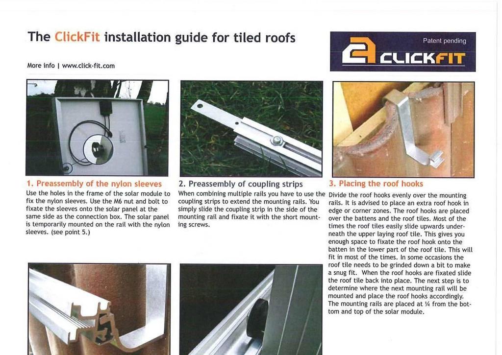
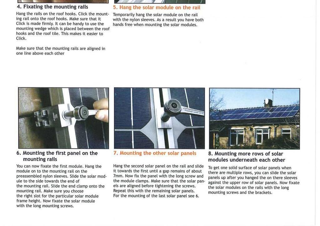
17 Annex A - Fixing instructions for the Click Fit system Page 17 of 18
18 ==============REPORT ENDS============= Page 18 of 18