WATER AND SANITARY SEWER
|
|
|
- Maximilian Stevenson
- 5 years ago
- Views:
Transcription

1 RUBIDOUX COMMUNITY SERVICES DISTRICT WATER AND SANITARY SEWER DESIGN & CONSTRUCTION MANUAL
2 THIS PAGE INTENTIONALLY BLANK
3 RUBIDOUX COMMUNITY SERVICES DISTRICT WATER AND SANITARY SEWER SYSTEM DESIGN AND CONSTRUCTION MANUAL JANUARY 2005 Mailing Address: P.O. Box 3098 Rubidoux, CA Street Address: 3590 Rubidoux Blvd. Rubidoux, CA 92509


4

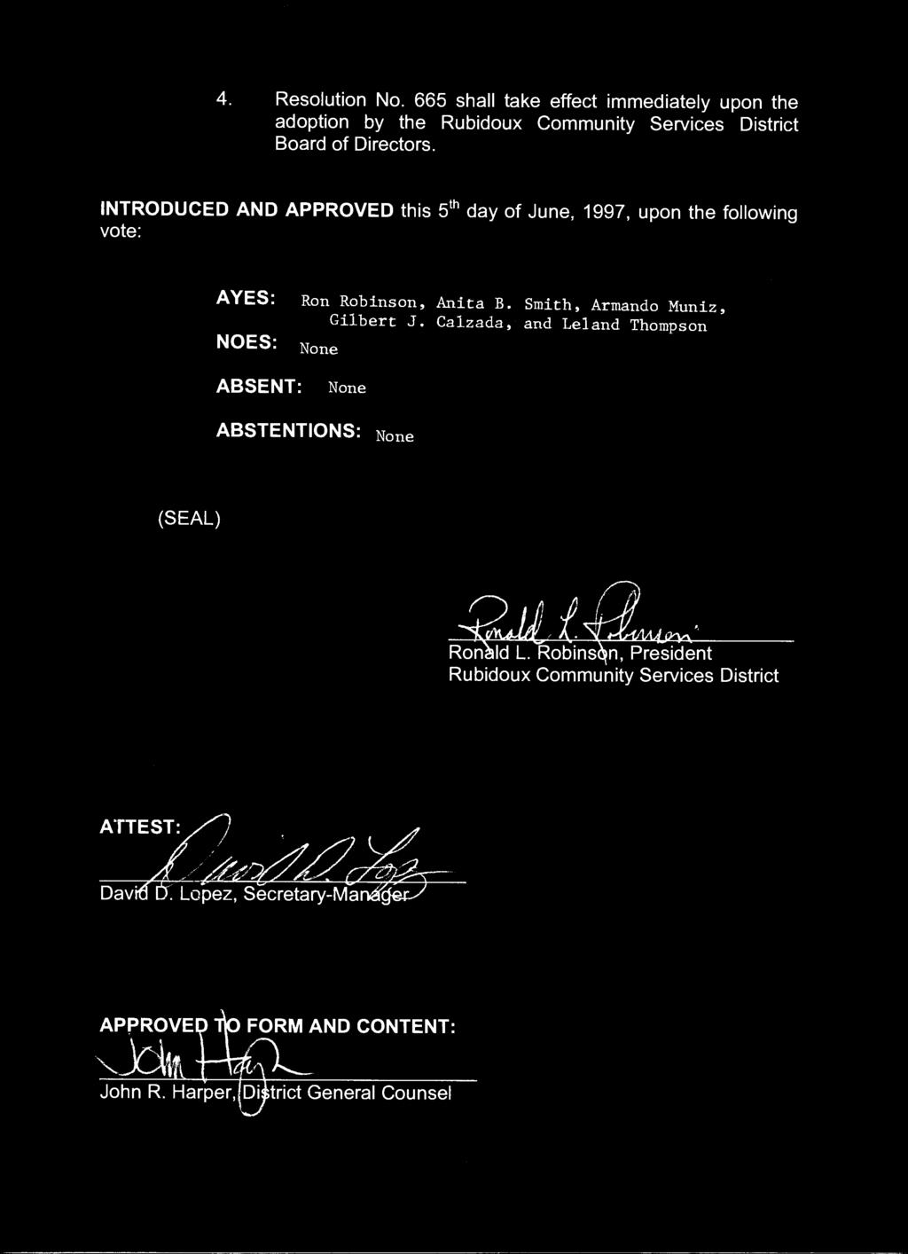
5
6 REVISIONS LISTING The Rubidoux Community Services District will periodically issue revisions to this manual. With each revision, the District will reissue this page showing all updates issued since the last time the entire manual was issued. It is the responsibility of the user to confirm receipt of all updates by contacting the District. REV. NO. DESCRIPTION DATE SECTION PAGES 1 Entire Manual 6/97 All All (Initial Distribution) 2 Entire Manual 1/05 All All (Complete Revision) 1/05
7 RUBIDOUX COMMUNITY SERVICES DISTRICT WATER AND SANITARY SEWER SYSTEM DESIGN AND CONSTRUCTION MANUAL TABLE OF CONTENTS SECTION i SECTION I SECTION II SECTION III SECTION IV SECTION V SECTION VI SECTION VII SECTION VIII SECTION IX APPENDICES RCSD RESOLUTION INTRODUCTION CONSTRUCTION DRAWING APPROVAL CONSTRUCTION DRAWING PREPARATION WATER DESIGN CRITERIA SEWER DESIGN CRITERIA WATER AND SEWER SYSTEM CONSTRUCTION RCSD APPROVED MANUFACTURED MATERIALS TECHNICAL SPECIFICATIONS STANDARD DRAWINGS i I II III IV V VI VII VIII IX 1/05
8 THIS PAGE INTENTIONALLY BLANK
9
10
11 SECTION I INTRODUCTION TABLE OF CONTENTS A. GENERAL I-1 B. POLICY I-1 C. REQUIREMENTS I-1 D. SAVINGS I-2 1/05
12 SECTION I INTRODUCTION A. GENERAL In 1952 the Rubidoux Community Services District was formed under the Community Services District Act to provide, among other services, water supply and wastewater disposal to the Rubidoux area of Riverside County in a safe, reliable, environmentally sensitive, and financially responsible manner. The Rubidoux Community Services District is a public agency governed by an elected five member Board of Directors to serve four-year staggered terms. The District is directed by its General Manager and Assistant General Manager. The Rubidoux Community Services District supplies its customers water for potable and non-potable uses, as well as providing sewer service. Potable water users are supplied from Rubidoux Community Services District s potable production wells. Non-potable users are supplied from Rubidoux Community Services District s non-potable wells. B. POLICY Rubidoux Community Services District s basic policy is that the user benefiting from the service must pay for the cost of the necessary facilities. The District normally designs and constructs all primary facilities and the Developer designs and constructs all secondary facilities. Primary facilities are those facilities required to produce and deliver water to each pressure zone from water sources, whether domestic or imported. Storage facilities, pumping stations, treatment facilities, water production wells, and major supply pipelines are considered to be primary facilities. Secondary facilities are designated as those facilities necessary to distribute the required waters throughout a pressure zone. Distribution mains, pressure reducing stations, and pipeline appurtenances are considered to be secondary facilities. In some situations, minor pumping stations, reservoirs and transmission mains may be considered secondary facilities when their function can be entirely locally defined. The District may elect, at its discretion, to oversize secondary facilities to meet anticipated future demands. In such cases, the District may fund the oversizing as a primary facility. At the discretion of the District s General Manager, deviations from these requirements may be allowed. All requests for variances to these requirements must be in writing, stating the reasons for the request. In the event of any discrepancy between portions of this document, or any referenced document, the District reserves the right to hold the Developer/Engineer/Contractor to the more stringent requirements. C. REQUIREMENTS 1. The Developer shall design, construct, and dedicate to the Rubidoux Community Services District the secondary water facilities in accordance with the requirements of the Rubidoux Community Services District. I-1 1/05
13 2. The Developer shall provide all financial arrangements necessary to plan, design, and construct the project. 3. The Developer shall obtain and dedicate water and/or sewer utility rights-of-way to the Rubidoux Community Services District. 4. The Developer shall pay current applicable fees in addition to completing those requirements listed above. Fees may include: Plan Checking fees, Connection Charges, Inspection Fees, and Meter Charges. District Staff should be consulted for current and applicable fees. 5. The Rubidoux Community Services District will review all drawings, and may revise, modify, or require redesign of any concepts, drawings, or details submitted. All concepts and drawings must be approved by the District Engineer, General Manager, and/or the Assistant General Manager. 6. The Developer shall provide the District with a corrosion site survey for all CML/CMC steel and ductile iron pipelines. If required, the Developer shall have cathodic protection design performed by a qualified engineer. 7. Procedures for development of water and/or sewer systems are similar for Tract Map developments, Parcel Map developments, and single lot main extension developments. Most procedures and design requirements herein have been prepared for Tract Map developments, but certain portions apply to all water and/or sewer system development work within the Rubidoux Community Services District s service area. 8. When applicable, the Developer shall also submit for review all improvement drawings within existing or future public rights-of-way for approval by the County of Riverside Transportation Department. All plan check, inspection and permit fees required by the County shall be paid by the developer, and all other requirements of the County shall be fulfilled prior to any construction within the public rights-of-way. D. SAVINGS If any provision of this manual are held to be contrary to law by a court of competent jurisdiction, or by the final tribunals of appropriate regulatory agencies, such provisions will not be deemed valid and subsisting except to the extent permitted by law, but all other provisions will continue in full force and effect. I-2 1/05
14 THIS PAGE INTENTIONALLY BLANK
15 SECTION II PROCEDURES CONSTRUCTION DRAWING APPROVAL TABLE OF CONTENTS A. CONSTRUCTION DRAWING APPROVAL II-1 1. Submit the Required Plan Check Deposit II-1 2. Submit Tract Water and/or Sewer System and Hydraulic Analysis II-1 3. Submit First Plan Check II-2 4. Submit Subsequent Plan Checks II-3 5. Submit Original Construction Drawings for Approval II-3 6. Provide the District with the Drawings II-3 1/05
16 SECTION II PROCEDURES CONSTRUCTION DRAWING APPROVAL A. CONSTRUCTION DRAWING APPROVAL District Staff will review all water and/or sewer construction drawings and may revise, modify, or require redesign of any concepts, drawings, or details submitted. All concepts and drawings must be approved by District staff. Construction must begin within one year of approval of the Water and/or Sewer Construction Drawings. If more than one year has elapsed, the project must go through the plan check procedure again before starting construction. The steps required to obtain Water and/or Sewer Construction Drawing approval is as follows: 1. Submit the required Plan Check Deposit. 2. Submit Tract Water and/or Sewer System and Hydraulic Network Analysis (Water). 3. Submit first plan check. 4. Submit subsequent plan checks. 5. Submit original Construction Drawings for approval. 6. Provide the District with the drawings. A flow chart for Construction Drawing Approval is shown in Appendix A. A plan check status sheet to be used by the District is shown in Appendix B. Each required step is discussed in detail below: 1. Submit the required Plan Check Deposit - The Plan Check Deposit will be determined by the District and shall be submitted prior to any Staff effort commencing on the project. 2. Submit Tract Water and/or Sewer System and Hydraulic Network Analysis (Water) Approximately one week after receiving the plan check deposit, District Staff will provide hydraulic grade elevations at connections to the District s water system. For the sewer facilities, the District Staff will provide contributing sewer flows at connections to the District s system. If the District has no data on existing contributing sewer flows, then the District may direct the developer to measure the sewer flows at selected manholes. In addition, District Staff may request analysis of project impact on existing downstream facilities. District Staff may, in addition, provide design recommendations for the water and/or sewer systems. For Commercial and Industrial developments, pretreatment may be required in accordance with District Ordinance No Based on the hydraulic grade elevations, contributing sewer flows, and design recommendations provided by the District, Developer shall submit to the District the following: a. One copy of the County of Riverside Conditions of Approval. II-1 1/05
17 b. Two copies of a master plan of the Tract with the proposed water and/or sewer facilities super-imposed on same. For the water facilities, Said plan shall show the node network, pipeline diameters, length, elevation at nodes, valve locations, and fire hydrant locations. For the sewer facilities, said plan shall show sewer manholes, diameter and slopes of sewers between manholes, and average daily flow for each reach of sewer between manholes. c. Two copies of the hydraulic network analysis of the proposed water system and two copies of the sewer system analysis of the proposed sewer facilities. d. Fire flow letter from the Riverside County Fire Department. Details regarding the hydraulic network analysis are included in Section IV, WATER DESIGN CRITERIA. District Staff will review the Tract Water and/or Sewer system, the hydraulic network analysis, and the sewer system analysis and return one set with comments to the Developer. Minor revisions may be incorporated in the first plan check submittal. If major revisions are required, the Tract Water and/or Sewer system and hydraulic network analysis shall be resubmitted until approved by District staff. 3. Submit First Plan Check - After review and approval of the Tract Water and/or Sewer System and hydraulic network analysis, Developer shall submit the following, as applicable: a. Three copies of the water and/or sewer construction drawings. b. One copy of the street improvement drawings. c. One copy of the grading plan. d. One copy of the approved Tract Water and/or Sewer System, hydraulic network analysis and sewer system analysis. e. Two copies of easement documents. f. One copy of the Tract/Parcel Map. g. One copy of the Corrosion Site Survey (for Steel and Ductile Iron Pipe only) h. Copy of receipt showing submittal to the County for plan check of facilities within the public rights-of-way. Submittals must be complete or they will be rejected. Each submittal shall include a transmittal listing all items submitted and referencing the District project number. Details regarding preparation of construction drawings and easement documents are included in Section III, CONSTRUCTION DRAWING PREPARATION. Details regarding waterline design criteria are included in Section IV, WATER DESIGN CRITERIA. Details regarding sewerline design criteria are included in Section V, SEWER DESIGN CRITERIA. Water and sewer drawings should be combined and shown on the same drawing whenever possible. II-2 1/05
18 The District will provide comments on one set of the water and/or sewer construction drawings and return same to the Engineer for revision. The goal of the District Staff is to complete the first plan check within three weeks of receipt of the submittal. Plan review time varies depending on the number of plans in the review process, size of project, complexity of the plans, and completeness of the drawings. 4. Submit Subsequent Plan Checks - For each subsequent plan check, the Developer shall submit the following: a. The previous District plan check set and a copy of the previous District transmittal. b. Three copies of the revised Water and/or Sewer construction drawings. c. Two copies of easement documents. d. Any additional material requested. Submittals must be complete or they will be rejected. If drawings and easement documents are not yet satisfactory, the District will make comments on one set of the drawings and easement documents and return same to Engineer for revisions. This procedure will be repeated as necessary until drawings and easement documents are complete. If Engineer does not return the previous District plan sets, then the plan check procedure will start from the beginning including payment of the plan check deposit. Each cycle of the subsequent plan check would normally be completed in approximately three weeks. 5. Submit Original Construction Drawings for Approval - After all plan checks are completed and the water and/or sewer construction drawings are acceptable to the District, the original drawings shall be submitted to the District for signature. Prior to the District approval of the water and/or sewer construction drawings, Developer shall pay all remaining plan checking fees, capacity fees and submit: a. The previous District plan check set and one copy of the revised water and/or sewer construction drawings. b. A copy of the Tentative Tract/Parcel Map showing dedications of streets for road purposes and public utilities purposes, or c. Executed Grant of Easement, minimum width of 30 feet. 6. Provide the District with the Drawings - When the drawings have been fully approved by all agencies, the Developer shall provide the District with a clean set of photo mylars and three sets of bluelines for the District s use. In addition, the Developer s Engineer preparing the improvement plans shall submit a digital graphics file containing water and/or sewer facilities as necessary to facilitate transferring of the information into the District s mapping system. Details of this requirement are outlined in Section III, CONSTRUCTION DRAWING PREPARATION. II-3 1/05
19 SECTION III CONSTRUCTION DRAWING PREPARATION TABLE OF CONTENTS A. GENERAL III-1 B. COVER SHEET III-1 C. PLAN AND PROFILE SHEETS III-2 1. Plan Portion III-2 2. Profile Portion III-3 D. GRANT OF EASEMENTS III-4 E. APPROVAL AND CERTIFICATION BLOCKS III-5 F. DIGITAL GRAPHIC FILES III-6 1/05
20 SECTION III PROCEDURES CONSTRUCTION DRAWING PREPARATION A. GENERAL A licensed Engineer in the State of California experienced in the design of similar systems shall prepare the water and/or sewer system improvement drawings that are clear, concise, and meet District standards. Drawings shall be drawn in ink on D size mylar sheets (24 x 36 ) with a Rubidoux Community Services District approval block. The drawings shall be professional quality drawings especially prepared as WATER DRAWINGS or SEWER DRAWINGS. Work shall be of standard engineering practice and shall be legible and present the proposed construction without confusion. Water and sewer designs shall not be shown on the same drawings. B. COVER SHEET The cover sheet shall show as a minimum: 1. General notes (Appendix C ) 2. Legend (RCSD Standard Drawing G80) 3. Estimate of Quantities (RCSD Standard Drawing G60 and/or G70) 4. District Signature Block 5. Water and/or Sewer system Certification 6. Index of Drawings 7. Vicinity Map a. Scale b. North Arrow c. Street Names d. Title and location of project 8. Index Map a. Scale (1 =400 or 1 =100 ) b. North Arrow c. Tract layout with street names and lot numbers d. Proposed waterlines and/or sewerlines identified by size and type e. Symbols for all appurtenances i) Fire Hydrants vi) Water Services and/or sewer laterals ii) Air Valves vii) Detector Checks iii) Blowoffs viii) Manholes iv) Tees and Crosses ix) Cleanouts v) Valves f. Sheet numbers corresponding to Plan and Profile sheets The use of a second sheet to include all information is permissible. III-1 1/05
21 C. PLAN AND PROFILE SHEETS The plan/profile sheets shall be drawn at a horizontal scale of 1 = 40 and a vertical scale of 1 = 4, and as a minimum the drawings shall show the following: 1. Plan Portion a. Title Block - The Title Block shall show the Tract Number, and scale of drawings. District approval blocks shall be incorporated into the title block. b. North Arrow - The North Arrow shall point up or to the left if possible to conform with item k. c. Right-of-way - Existing and proposed rights-of-way shall be identified with dimensions for same shown. d. Curb Separation - Existing and/or proposed curb separation shall be identified with dimensions for same shown. e. Easements - Existing or proposed easements shall be identified with dimensions for same shown. f. Street Names - All street names shall be shown. g. Lot Lines - All lot lines and parcel lines shall be shown. All lots shall be numbered or labeled. All adjacent Tracts shall be identified. h. Utilities - All existing and proposed utilities shall be shown. Utilities to be shown shall include, but not limited to, water (existing waterlines shall be identified by District Plan No.), sewer (existing sewerlines shall be identified by District Plan No.), gas, power, telephone, storm drain, irrigation, traffic, and cable television. Each utility shall be identified with a symbol and the size of the utility shall be shown. i. Existing and Proposed Improvements - All existing surface improvements shall be shown including, but not limited to, curb and gutter, edge of pavement, power poles, driveways, sidewalks, and fences. j. Match Lines - Match lines for each end of the street shall be shown as follows: Sta Match Line See Sheet 5 k. Stationing - Stationing along the centerline of the improvement shall be shown. Unless otherwise specified, stationing shall increase from left to right. Stationing shall be identified with tick marks at 100 intervals. l. Proposed Pipeline - The proposed pipeline shall be indicated with a heavy line. Dimensions from street centerline to centerline of pipeline shall be shown. Pipeline shall be identified as: C L CML&C ( Gauge Minimum) Pipeline or III-2 1/05
22 C C-900 (Class ) Pipeline L m. Appurtenances - All appurtenances including tees, crosses, elbows, and blind flanges or plugs shall be identified by station and size as follows: Sta C 12 x 12 x 8 Tee L All pipeline appurtenances including air valves, blowoffs, fire hydrants, valves, manholes, and cleanouts shall be identified by station, size and Rubidoux Community Services District Standard Number as Follows: Sta C 2 Air Valve per RCSD Std. Dwg. No. L All water meter services and sewer laterals shall be indicated on the drawings. The stationing of services and sewer laterals is not required on the drawings, however, after construction of proposed facilities, the engineer shall provide the District with an as-built stationing table of the services on the record drawing. All connections to existing water and/or sewer systems shall be identified by station and size. A station equation and District plan number shall be used to reference existing water and/or sewer lines. Details for connections shall be used where required. 2. Profile Portion Only profiles for water and sewer shall be shown. All other utility profiles shall not be shown unless conflicting or where crossing over or under (i.e. storm drain). a. Stationing - Stations shall be shown along the bottom of the profile at 100 intervals. Profile stationing shall line up with plan stationing. b. Elevations - Elevations shall be shown on both ends of the profile sheet. c. Existing and Proposed Ground Surface - Existing ground surface or pavement over the proposed pipeline shall be identified as follows: Existing Top of Pavement (or ground surface) over Centerline of Pipeline Proposed ground surface or pavement over the proposed pipeline shall be identified as follows: Proposed Top of Pavement (or ground surface) over Centerline of Pipeline d. Match Lines - Match lines for each end of the sheet shall be shown as follows: Sta Match Line See Sheet 5 e. Flow Lines (FL) - Flow lines of the proposed pipeline shall be identified as follows: FL CML&C ( Gauge Minimum) Pipeline or FL C-900 (Class ) Pipeline f. Stationing and Flow Line Elevation - Pipeline stationing and flow line elevations shall be shown for each grade break (GB) as follows: III-3 1/05
23 Sta GB FL Pipeline Stationing and flow line elevations shall be shown for each tee, cross, elbow, BC, EC, hot tap, and end of pipeline as follows: Sta x12 x8 Tee FL Pipeline stationing and flow line elevations shall be shown for all air valves, blowoffs, and fire hydrants as follows: Sta Blowoff FL Sewer stationing and flow line elevations shall be shown into and out of each sewer manhole as follows: Sta FL Pipeline stationing and flow line elevations shall be shown for each utility crossing. g. Pipeline Lengths and Pipeline Slopes - Pipeline lengths and pipeline slopes shall be shown between all grade breaks as follows: S= LF PVC (or CML&C) h. Maximum trench width and Load Factor For gravity sewers, the maximum trench width and load factor shall be shown. i. Welded Joint Limits - Length of welded joints for welded steel pipe shall be identified as Fully Welded Joints with station limits shown. j. Minimum cover - 42 minimum cover (48 minimum cover in unpaved areas) shall be shown between top of pipe and existing or proposed ground surface. k. Maximum Cover - The maximum cover shall be 8 between the top of pipe and existing or proposed ground surface. A checklist for the preparation of water Construction Drawings is shown in Appendix D. D. GRANT OF EASEMENTS The Grant of Easement shall be on District form and shall consist of three parts: The Grant of Easement form; the legal description; and the plat map. The legal description shall be designated as Exhibit A and if appropriate shall have the assessor s parcel number indicated on the upper right corner of the exhibits. The legal description shall be prepared by a California Registered Civil Engineer or Land Surveyor and signed and stamped by said engineer or surveyor. The plat shall be designated as Exhibit B and shall be prepared by a California Registered Civil Engineer or Land Surveyor and signed and stamped by said engineer or surveyor. III-4 1/05
24 A copy of the Grant of Easement form is shown in Appendix E. E. APPROVAL AND CERTIFICATION BLOCKS 1. Water and Sewer Certification (Cover Sheet only). On plans for system improvements proposed to become part of the District shall have the following: WATER CERTIFICATION BLOCK I certify that the design of the Water System in Tract No. is in accordance with the water system master plans of the Rubidoux Community Services District, and that the water service, storage and distribution system will be adequate to supply water service to said tract. This certification does not constitute a guarantee that it will supply water to said tract at any specific quantities, flows, or pressures for fire protection or any other purpose. Assistant General Manager/ District Engineer, RCE Date SEWER CERTIFICATION BLOCK I certify that the design of the Sewer System in Tract No. is in accordance with the sewer system master plans of the Rubidoux Community Services District, and that the waste disposal system is adequate at this time to treat the anticipated wastes from the proposed tract. Assistant General Manager/ District Engineer, RCE Date 2. Approval Signature Block (same location on all sheets) Approved by the Rubidoux Community Services District for Construction: Date Assistant General Manager/ District Engineer, RCE Void after one year from this date III-5 1/05
25 F. DIGITAL GRAPHIC FILES The District requires the developer s engineer preparing improvement plans to submit one consolidated graphics file indicating the entire improvement area. The graphics file must contain water and/or sewer pipelines, improvement area boundary, street centerline, right-of-way, and lot/parcel line data to facilitate transferring the information into the District s mapping system. The digital drawing shall be at a 1:1 scale, and will be required prior to the District signing the plans. If the Developer s engineer does not have the capability to provide such files, the District will input the data into the existing mapping system and recover the costs from the Developer. 1. Format of Data for Conversion - The preferred format for digital submissions of the graphical data is AutoCAD Release 2000 or newer. The District will also accept the generic DXF format or Shape (.SHP) file. 2. Digital Media Formats All digital information shall be submitted to the District on one of the following: CD ROM; 3 ½ Windows formatted diskette (1.44 Mb); or (steve@rcsd.org) All media will be submitted with labels indicating the following information: DATE: MAP NAME: RCSD WO NO. COMPANY: MEDIA CREATOR: FILE NAME: (date submitted) (TR, PM, PP, ETC.) (leave blank) (engineering firm) (person creating the diskette) (Filename with extension) 3. Requirements for Hardcopy Submission - In conjunction with the digital submission of the proposed improvements, a printed overall layout of the information will be required. The scale of this plan shall be either 1 =100, 1 =200, or 1 =400 whichever best fits a D-size (24 x 36 ) drawing sheet. 4. Data Integrity - Common points must be coincident to within A tie to a known location point is required, such as: section corners, quarter corners, street intersections, etc. The tie coordinates will be based on the California State Plane Coordinate system (NAD 83) in at least two locations, preferably on opposite sides of the area being mapped. 5. Symbol Representation - All water and sewer symbols will conform to those shown in RCSD Standard Drawing G80. To aid the engineers with standardization of these symbols, the District will make the symbols available electronically in AutoCAD format. 6. Data Layering Requirements - The data will be layered into the following features: a. Boundary Data f. Tie Data b. Road Centerline Data g. Waterline Data (if applicable) c. Lot/Parcel Data h. Sewer Data (if applicable) d. Rights-of-Way Data i. Miscellaneous e. Easement Data III-6 1/05
26 Essentially, data specific to the improvements being submitted which is directly applicable to the landbase maintenance is to be separated and split into corresponding layers. All other data is transmitted on a single layer. The following table indicates which features must be transmitted digitally and which are desirable but not required: a. Boundary Data: Boundary Line Map Name Bearings/Distances/Curve Data b. Road Centerline Data: Centerline Street Name Bearings/Distances/Curve Data Required Required Optional Required Required Optional c. Lot/Parcel Data: d. Right-of-Way Data: e. Easement Data: f. Tie Data: g. Waterline Data: Assessor Parcel Numbers Lot Lines Lot Numbers Lot Bearings Lot Distances Right-of-way Lines Descriptive Data Bearings/Distances/Curve Data Easement Lines Descriptive Data Bearings/Distances/Curve Data Graphic Representation Ca State Plane Coord Values Bearings/Distances/Curve Data Water Lines Valves, and other appurtenances Descriptive Data Required Required Required Optional Optional Required Optional Optional Required Optional Optional Required Required Optional Required Required Required h. Sewer Data: Sewer Lines Required Manholes, and other appurtenances Required Descriptive Data Required i. Miscellaneous: All other Data Optional III-7 1/05
27 SECTION IV WATER DESIGN CRITERIA TABLE OF CONTENTS A. HYDRAULIC NETWORK ANALYSIS CRITERIA IV-1 B. WATER CONSTRUCTION DRAWING CRITERIA IV-2 1/05
28 SECTION IV WATER DESIGN CRITERIA Water system improvements, including reservoirs and pump stations, proposed for inclusion into the Rubidoux Community Services District service area shall be designed in accordance with all appropriate AWWA standards and the following criteria: A. HYDRAULIC NETWORK ANALYSIS CRITERIA The District reserves the right to determine the criteria for each water system or sub-system based upon conditions that may exist for that particular location, anticipated level of development, planned use, or other criteria. In general, however, the water system shall be sized to handle the highest demand within the general area of the tract and shall conform to the following minimum standards: 1. Pipeline Diameters - The minimum pipeline diameter for residential areas is 8. The minimum pipeline diameter for commercial/industrial areas is 12. The District accepts only the following diameters: 8, 12, 16, 20, and 24. Larger sizes will be considered on a case by case basis. The District reserves the right to specify sizing of any pipeline. In some instances, the District may require a larger size pipeline than normally required for system distribution requirement purposes. Rubidoux s Board of Directors may authorize participation and payment of increased cost of such pipeline in accordance with District criteria. 2. Pipeline Friction Factors - Pipeline friction factors shall be as follows: Pipe Material Hazen-Williams Coefficient Polyvinyl Chloride C=130 Cement Mortar Lined Steel C=120 Ductile Iron C= Water System Unit Demands - Average Day unit demands shall be as follows: Land Use Residential Average Day Unit Demand Factors 900 gpd/du (1 acft/yr/du) All other land uses shall be analyzed separately. The Developer will be required to submit analysis of the anticipated flow demands, as specified in Section 6 herein. The District shall accept or modify the submitted analysis as necessary. 4. Peaking Factors - The peaking factors to be used are as follows: a. b. Maximum Day Demand: The Maximum Day Demand shall equal 2.0 times the Average Day Demand. Peak Demand: The Peak Demand shall equal 3.0 times the Average Day Demand. 5. Fire Flow - The fire flow requirements shall be in accordance with the applicable standards of the Insurance Services Office (ISO) and shall be those required by the Riverside County Fire Department for the type of development under construction. IV-1 1/05
29 6. System Analysis - The proposed water system shall be analyzed for the following two conditions: a. Peak Demand b. Maximum Day Demand plus fire flow For the Peak Demand flow condition, the pressure at each node shall be designed for 40 psi minimum. The maximum pressure at each node shall be 120 psi. The maximum velocity in the pipe shall be 5 feet per second. For the Maximum Day Demand plus fire flow, the pressure at each node shall be a minimum of 20 psi and a maximum of 120 psi. The maximum velocity in the pipeline shall be 10 feet per second. Fire flow shall be taken from the hydrant furthest from the connection(s) to the District s distribution system, at the highest elevation, and as directed by the District. B. WATER CONSTRUCTION DRAWING CRITERIA 1. Pipeline Location - Unless otherwise approved by the District, all waterlines shall be located on the South or West side of the street, 7 feet off of the curb face or berm per Riverside County Road Department standards. Location shall not interfere with other existing utilities. See RCSD Standard Drawing G10. Pipe joint deflection shall not be more than the manufacturer s recommended offset in a curved alignment. The joint deflection angle shall be indicated on all horizontal and vertical curves. Waterline installation near sewer lines shall be in accordance with the State Department of Health Services, Criteria for the Separation of Watermains and Sanitary Sewers and RCSD Standard Drawing W1010. In general, waterlines should cross perpendicular to sewer lines a minimum of 1 foot above the sewer. If the waterline crosses beneath the sewer, then it should have a minimum separation of one foot, have no joints within 10 feet of each side of the sewer and shall be constructed of materials per aforementioned Standard Drawing. Waterlines parallel to sewer lines shall be located a minimum of ten feet from the sewer (outside diameter to outside diameter). When crossing other utilities, provide a minimum of one foot vertical clearance. The District will require pipeline looping whenever possible. Dead-end mains are undesirable. 2. Minimum Pipe Cover - The minimum cover over the top of the pipe shall be 42 from finished paved road grade (48 if unpaved), and shall provide adequate depth so that the gate valve stems and operating nuts have a 12 clearance to finished road grade. District Staff may increase or decrease this required dimension as necessary to cover non-standard conditions. When the required cover cannot be provided, concrete encasement or protective slab construction over the pipeline may be required. Consult with District staff. Pipelines shall be installed after roads are constructed to final sub-grade, and the developer certifies this in writing on District form. IV-2 1/05
30 3. Pipe Materials - Unless otherwise authorized by the District, all waterlines 12 and smaller shall be Polyvinyl Chloride (PVC) Pipe, Cement mortar lined and cement mortar coated welded steel pipe, or ductile iron pipe in accordance with AWWA and District standards. All waterlines 16 and larger shall be cement mortar lined and cement mortar coated welded steel pipe or ductile iron pipe in accordance with AWWA and District standards. Refer to the Technical Specifications for more detailed information. Minimum allowable pipe shall be as follows: PVC = Class 150 CML&C Steel Pipe, All sizes = 10 ga Ductile Iron Pipe = Class 150 Pipe shall be provided only from District approved pipe manufacturers. See Section VII, LIST OF APPROVED MANUFACTURED MATERIALS Pipe Slope - The minimum pipe slope of waterlines shall be 0.5% unless otherwise authorized by the District. Thrust Restraint - The Engineer shall analyze all likely thrust loads and conditions in water lines including those at elbows, tees, crosses, ends, and angle points greater than 2 degrees. Thrust shall be restrained by the use of thrust blocks per RCSD Standard G40 for PVC pipe, by restrained joints for ductile iron pipe, and welded joints for welded steel pipe per RCSD Standard Drawing W1240. For special circumstances, particularly where joining to existing pipe when the joint type is unknown, thrust blocks, or thrust collars may be substituted for joint welding. Always construct thrust blocks against undisturbed earth. Calculate bearing areas using allowable bearing load of 1,500 psf or other engineering value. 6. Valves - Valves 12 and smaller shall be flanged resilient wedge gate valves per District standards. Valves 16 and larger shall be flanged butterfly valves per District standards. Valves shall be the same size as the nominal pipeline diameter. Gaskets are to be high quality natural or synthetic rubber, non-asbestos, ring type, sized for flanges to be provided. Three valves shall be installed on each tee and four valves shall be installed on each cross. Valves shall be spaced at 1,000 foot maximum intervals or as directed by the District staff. 7. Fire Hydrants - Fire hydrants shall be in accordance with District standards, constructed at right angles to the waterline. Fire hydrants shall be located per the requirements of the Riverside County Fire Department as stated in the Tract Conditions of Approval but no greater than 330 foot intervals. 8. Air Valves - Air valves shall be combination air vacuum and air release valves in accordance the AWWA and District standards, constructed at right angles to the waterline. Air valves shall be located at all high points in the pipeline and downstream of valves. Minimum size of air valves shall be 1 and shall be sized as follows: Pipeline Diameter Air Valve Size and and Larger Consult with District staff 9. Blowoffs - Fire hydrants shall be used in place of blowoffs. Blowoffs shall be located at all low points in the pipeline, at all dead-ends or terminal points, and upstream of valves. Minimum size of blowoffs shall be 2. Consult with District Staff regarding required size. IV-3 1/05
31 10. Services Installations - Service Installations shall be in accordance with District standards, constructed at right angles to the water main. No water service laterals shall be installed between appurtenances (i.e. fire hydrants, blowoffs, air valves, etc.) and pipeline dead-ends. All requests for domestic and irrigation service installations larger than 1 must be specifically approved in writing by the District. All non-residential water services shall have a District approved backflow prevention device installed adjacent to the meter unless otherwise approved by the District. Additionally, as specified by the District Engineer, certain residential services shall also be installed with District approved backflow prevention devices. 11. Minimum Design Pressure - The minimum design pressure shall be the static pressure plus 50%. 12. Control Valves, Pressure Relief Valves, and Other Special Valves - Control valves, pressure relief valves, and other special valves shall be designed and located as directed by District staff. 13. Easement Criteria - Pipelines that cannot be located within the public right-of-way must be located in easements granted to the District on the District s Grant of Easement form. Easements shall be a minimum of 30 feet in width unless otherwise approved in writing by the District. Easements for other utilities may overlap the District easement only if proper separations are maintained. Details for Grant of Easement documents are in Section III, CONSTRUCTION DRAWING PREPARATION. 19. Protection of Appurtenances Depending on the location, above-ground water appurtenances may require guard posts or concrete retaining walls. When required by the District Engineer, or when shown on the approved plans, guard posts or retaining walls shall be installed in accordance with the District's Standard Drawing G130 and/or W1160. IV-4 1/05
32 THIS PAGE INTENTIONALLY BLANK
33 SECTION V SEWER DESIGN CRITERIA TABLE OF CONTENTS A. GENERAL V-1 B. SEWERS AND APPURTENANCES V-1 C. FUTURE DEVELOPMENT V-4 D. MANHOLES AND CLEANOUTS V-4 E. SEWAGE LIFT STATIONS AND INVERTED SIPHONS V-5 F. INDUSTRIAL WASTE PROVISIONS V-5 1/05
34 SECTION V SEWER DESIGN CRITERIA The following pertain to the design of the various components within the sewage collection system. Exceptions and deviations from these specifications may only be made with approval, in writing, by the District Engineer, General Manager, or the Assistant General Manager for the Rubidoux Community Services District. A. GENERAL 1. Scope - All sewers, sewage lift stations, treatment facilities and appurtenances to be owned, maintained and/or operated by the District shall be designed according to the criteria set forth in this section. The criteria shall hold for systems served but not owned, maintained and/or operated by the District insofar as said criteria may affect the efficiency of the District s system. All additions to the District s system shall be plan checked and inspected by the District Design Competence - All District facilities shall be designed by California Registered professional engineers knowledgeable in sewer design and construction practices, and according to accepted practices in the sewerage field. Sewage Lift Station and Inverted Siphons - Every effort should be made, within economic reason, to avoid sewage lift stations, inverted siphons and exposed piping. Their use will be allowed only upon written approval by the District. Legal Access - Each lot to be served by sewer shall abut a public street or recorded easement containing a sewer, or provided with permanent legal access to such a sewer. The location of the street, easement or legal access shall permit gravity flow from the lot to the sewer main. Deviation from any of the criteria adopted herein may be permitted upon written request to and approval by the District. B. SEWERS AND APPURTENANCES 1. Flows - The flow used for the design capacity for sewers and sewage lift stations shall be the computed peak flow, which shall be determined on the basis of projected land use and average daily per Dwelling Unit flow. The average per Dwelling Unit flow shall be as follows: DWELLING UNIT TYPE GPD/DU Single Family 270 Multi Family 270 Sewer flows shall be computed from projected land use and population density over the area tributary to the sewer reach under consideration. The peak flow for the above units consists of a peaking factor multiplied by the average daily flow as given in the following formula: Q peak = 23..(Q avg ) 089 Design flows from commercial and industrial areas shall be determined in consultation with the District. V-1 1/05
35 2. Formula - Capacity of all sewers shall be determined by the use of the Manning formula: Q = A r s 2 n Where: Q = flow capacity, CFS A = cross-sectional area, ft 2 n = coefficient of roughness r = hydraulic radius, ft s = slope Pipe Materials - Sewers shall be specified to be extra strength vitrified clay pipe (VCP) or Polyvinyl Chloride (PVC) unless authorized otherwise by the District. All materials shall conform to and be installed in accordance with District standards. Refer to the Technical Specifications for more detailed information. Roughness Coefficient - The roughness coefficient used in design shall be n = for all sewers. 5. Pipe Size - All gravity sewer pipe up to and including 10 diameter shall be sized to carry the peak flow when flowing half full (50%). All larger sewer pipe, except those designed as laterals, shall be sized to carry the peak flows when flowing three-quarters full (75%). No sewer main with an internal diameter less than 8 shall be installed without written approval of the District. 6. Design velocities - The purpose of this requirement is to prevent sewage sedimentation and subsequent generation of corrosive gases. Design velocities at design flow (Q) are presented below: Preferred Minimum Extreme Minimum Sewer mains 3 fps 2 fps 1.5 fps Force mains 3 fps 2 fps 1.5 fps Inverted siphons 4 fps 3 fps 3 fps The maximum velocity at design flow allowed in any sewer pipe is 10 fps. 7. Sewer Slopes - Minimum slopes to be used with various pipe sizes are listed below: Diameter (Inches) Slope (ft/ft) Exceptions to minimum slopes - where topography limits or prevents the use of minimum slopes as described herewith, the District may require an engineer s report. This report shall describe the alternatives and their economies. The report shall also include an evaluation of prospective maintenance and sewer gas problems. Greater minimum slopes than those specified in the above hereof may be required where the presence of hydrogen sulfide may be detrimental to and affect the life of the sewer pipe being used. 9. Slopes in Force Mains - In force mains a continuous uphill slope shall be provided from the pressure sources to the outlet. The intention is to avoid formation of air pockets. V-2 1/05
36 10. Location - All sewer mains shall be located in public streets or recorded easements such that each lot within a development can be served by gravity flow, and the laterals shall be extended according to RCSD Standard Drawing S2080 or S2090. In public streets, the sewer main shall be located 6 feet from street centerline and whenever possible north or east of centerline. See RCSD Standard Drawing G Curved Sewers - Horizontal or Vertical sewers are prohibited. Sewer under Structures - No main sewer shall be located beneath a structure except as approved in writing by the District. Structural Integrity - Provisions shall be made in all cases to preserve the structural integrity of pipes, conduits, or structures affected. Depth of Sewer - Permission from the District must be obtained if the following minimum depths cannot be met. In general, the load on the pipe must be considered and adequate precautions taken to protect it, either by means of encasement, supports or added strength. Minimum Cover of pipe for various locations: Locations Sewer in Public Streets and easements Lateral at curb or edge of pavement Lateral at property line Stream crossings Depth 7 feet 5 feet 4 feet Below scour line Sewer Laterals - A sewer lateral serving a single family dwelling or equivalent shall be at least 4 inside diameter from the main to the right-of-way. Laterals for all other facilities shall be at least 6 from the main to the right-of-way. Sewer lateral design shall conform to RCSD Standard Drawing S2080 and requirements of the Technical Specifications. Sewer laterals in waterways, easements, and deep cuts should have the house service brought to a minimum depth of 5 feet. Backfill for sewer laterals within the public right-of-way shall be a controlled density fill material (cement slurry). Sewer laterals from opposite sides of the street shall be connected to the sewer main at different stations. A tee or wye shall be used for sewer lateral connections. The alignment of the lateral shall be perpendicular to the alignment of the sewer main. District approval shall be obtained prior to design of chimney and deep laterals. 16. Special Sewer Design Conditions - When it is necessary to construct sewers and appurtenances in areas where a potential erosion hazard exists, individual design considerations shall be given to provide additional protection to the sewer facilities to prevent their damage. Special design considerations can be applied to stream and canyon crossings, parallel construction to stream beds, construction on steep slopes requiring special anchorage, and shallow sewer construction in roadways. Concrete encasements, cut-off walls, special backfill material (cement slurry) and special erosion control facilities may be required. The sewer may be designed to pass under lawns in planned residential developments, but the design concept shall be reviewed by the District prior to Plan and Profile preparation. Sewer laterals of the same size as the sewer shall be connected by using a manhole. The drop across the manhole shall apply in accordance with RCSD Standard Drawing S2030. V-3 1/05
37 17. Clearance from other utilities - Special care shall be exercised in locating sewer lines near other utilities, and especially water lines. Sewer lines shall, whenever possible, by located 3 below water lines and where parallel installations occur, horizontal separation shall be maintained in accordance with RCSD Standard Drawing S Backwater Valves - Backwater valves shall be required whenever structures served by sewer laterals are subject to flooding in the event a sewer main stoppage causes the upstream manhole to overflow. Residences with slab elevations lower than street elevation shall have backwater valves (see RCSD Standard Drawing S2110) Backwater valves shall not be required wherever intermediate manholes can be placed to economically preclude the need for backwater valves (such spacing not to be less than 120 feet). Ordinarily, one additional manhole can be economically justified if it eliminates 4 backwater valves. Valves should be in accordance with the current District standard drawings and installed at the shallowest location allowing for future inspection and maintenance. The Design Engineer shall show all backwater valves and their locations where installations are proposed on private property by the property owner or developer. Those valves shall be indicated on both the location map (cover sheet) and the Plan and Profile sheets. 19. Protection of Appurtenances Depending on the location, above-ground sewer appurtenances may require guard posts or concrete retaining walls. When required by the District Engineer, or when shown on the approved plans, guard posts or retaining walls shall be installed in accordance with the District's Standard Drawing G130 and/or W1160. C. FUTURE DEVELOPMENT 1. Alignment design considerations for future development - Potential future development shall be considered when selecting alignment and depth. The District may require stub-outs for future extension and greater depths in order to meet the minimum required depths in future, adjacent developments. 2. Oversizing Required by the District - The District may find that the capacity of certain new sewers and pump stations within an area under development should be increased to accommodate existing or future additional development. In such a case, the quantity of additional flow shall be determined by the District. The flow resulting from the addition of the developer s and the District s computed peak flow shall be used as the basis of design. D. MANHOLES AND CLEANOUTS 1. Manhole Location and Spacing - Manholes shall be located at all junctions, all changes in direction, all changes in slope, and all changes in pipe size. When the distance between manholes required for the foregoing reasons exceeds 350 feet, good judgment should be used in placing intermediate manholes at points of probable sewer intersections, at beginning or end of curves, or lacking other reasons, at approximately equal intervals. In general, the maximum of 350 feet should be observed. Good judgment should be used in location of manholes along water courses. Manholes should not be placed directly in the water courses. Manholes shall conform to RCSD Standard Drawing S Manhole Inlet and Outlet - The sewer flow line of the inlet shall be designed with an elevation 0.10 foot greater than the outlet; however, if the manhole is designed at a grade break, the V-4 1/05
38 slope of the inlet sewer shall continue to the outlet before changing grade. If the manhole is designed to accommodate a change in direction of flow and the change in direction exceeds 45 degrees, the inlet shall be designed with an elevation 0.25 foot greater than the outlet. 3. Shallow Manholes - Manholes 3 feet or less in depth above the shelf shall be of special design. 4. Cleanouts - Dead-end sewers shall generally terminate in standard manholes. Cleanouts may be used within 175 feet of a manhole if there are no more than 4 connections between the cleanout and the nearest downstream manhole. Cleanouts shall be brought to ground surface in a long radius or two 45 degree angles with a full sewer diameter opening. Cast-iron frame and cover shall be provided. Dead-ends over 175 feet shall terminate in standards manholes unless future extension of said dead-end will include a manhole within 350 feet, in which case a temporary cleanout is permitted. Cleanouts shall conform to RCSD Standard Drawing S2070 and requirements of the Technical Specifications. All Sewer Lateral installations will have a cleanout installed at the property line. 5. Drop Manholes - Drop manholes shall be avoided if at all possible. Drop Manholes may be permitted after review by the District of the criteria creating the need. Drop manholes shall conform to RCSD Standard Drawing S Frame and Cover - All manholes and cleanouts shall have cast-iron frames and covers. Frames and covers shall conform to RCSD Standard Drawing S2060 and requirements of the Technical Specifications. 7. Manhole Diameters - Manholes shall be 48 inches in diameter minimum for sewer diameters 18 and less, and 60 inches in diameter for sewer diameters 21 and larger. 8. Marker Posts - Marker posts shall be required if manholes or cleanouts are to be installed outside of paved areas. E. SEWAGE LIFT STATIONS AND INVERTED SIPHONS 1. General - Sewage lift stations, inverted siphons or nonstandard construction should be avoided whenever possible. In situations requiring such installations, they shall be designed by the District, a District retained consultant, or the developer s engineer in conjunction with District staff. The District should be consulted in the early planning stages to access the need for such installations and to develop site specific design criteria. At that time, the District will determine whether the District or the developer s engineer will perform the design. 2. Residential Sewage Pumping Where gravity service is not feasible, special application may be made to the District to allow installation of a residential sewage pump system. The District must approve the design of the system, and the District reserves the right to prohibit the installation of a residential sewage pump system. When the installation of a residential sewage pump system is approved, the following general requirements must be met: a. Installation of the sewer ejector pump, electrical work, and holding tank, must: a) meet the codes and regulations of the building and safety department of the County of Riverside; and b) be inspected by an inspector from said building department. V-5 1/05
39 b. The discharge line from the building outlet to the sewage pump must be gravity flow and be equipped with a blowoff cleanout. The pressurized discharge line from the holding tank must be equipped with a check valve as close as possible to the holding tank, followed by a gate valve. The pressurized discharge line must be installed for the shortest distance feasible, at which point the pressurized line must be converted to gravity flow using a wye, and a cleanout must be installed on the flow portion of the wye. A pressurized discharge line will not be permitted to connect to the sewer main unless no other alternative is possible AND, in the opinion of the District, the sewer main can facilitate the pressurized connection. All gravity and pressure discharge lines must be inspected by a District inspector before being covered. F. INDUSTRIAL WASTE PROVISIONS 1. General - The Developers of all commercial/industrial projects shall provide the District with detailed information concerning the project s expected wastewater quantity and quality. The District will review this information and determine which of the following facilities are required: a. Building sewer sampler. b. Wastewater flow monitoring station. c. Gravity separator. d. Industrial Waste clarifier. e. Pretreatment facilities. V-6 1/05
40 THIS PAGE INTENTIONALLY BLANK
41 SECTION VI PROCEDURES FOR WATER AND SANITARY SEWER SYSTEM FACILITY CONSTRUCTION TABLE OF CONTENTS A. WATER AND SANITARY SEWER SYSTEM FACILITY CONSTRUCTION VI-1 1/05
42 SECTION VI PROCEDURES FOR WATER AND SANITARY SEWER SYSTEM FACILITY CONSTRUCTION A. WATER AND SANITARY SEWER SYSTEM FACILITY CONSTRUCTION All water and/or sewer facility projects shall be constructed by the Developer and inspected by District inspectors. Work performed without the knowledge or the observation of a District inspector will not be accepted. The steps required to obtain approval of construction of water and/or sewer facilities are as follows: 1. Submit the Inspection Deposit and other District required fees. 2. Provide Submittals, Water and/or Sewer System Construction Agreement, Bonds, and Certificate of Insurance. 3. Attend a mandatory Preconstruction Meeting 4. Notify the District Regarding the Start of Construction 5. Construct Water and/or Sewer System Facilities 6. Test and Disinfect the Water and/or Sewer System Facilities 7. Provide Continuity Test (Welded Steel Water pipe only) 8. Pay Remaining Inspection Fees 9. Connect to Existing Water and/or Sewer System 10. Submit Application for unmetered Construction Water (Water) 11. Remove Unmetered Connections (Water) 12. Provide unconditional Lien Waiver and Release, Water System Grant Deed and/or Sewer System Grant Deed, and Record Drawings. 13. Install Permanent Meters (Water) 14. Notice of Completion Filed by the District. A flowchart for Water and/or Sewer system facility construction is shown as Appendix F. A construction status sheet to be used by the District is shown in Appendix G. Each required step is discussed in detail below: 1. Submit the Inspection Deposit - The inspection deposit, any other District fee, and three copies of the approved water and/or sewer construction drawings shall be submitted. VI-1 1/05
43 2. Provide Submittals, Water and/or Sewer System Construction Agreement, Bonds, and Certificate of Insurance - The Developer shall submit to the District Staff the following: a. Contractor information sheet (Appendix H ) b. Materials list, in accordance with RCSD approved Materials listed in Section VII. c. Two copies of Encroachment Permits d. One copy of the recorded tract/parcel map showing dedication of streets for road and public utility purposes (not required if executed Grant of Easement was provided earlier) e. Water and/or Sewer System Construction Agreement (Appendix I ) After the District executes the Water and/or Sewer System Construction Agreement, approves the Contractor, and approves the material list, Developer shall submit the following: a. A copy of the Contract between the Developer and Contractor verifying the cost of water and/or sewer system facility construction b. Certification of streets to final grade (Appendix J ) c. Certificates of Insurance for Contractor (Appendix K ) d. Faithful Performance Bond (Appendix L ). Performance bonds provided to the County are satisfactory if the facilities to be turned over the District are included. After the District reviews and approves all submittals, the Developer shall schedule a preconstruction meeting with the District. A one week notice is required prior to said preconstruction meeting. 3. Attend a Mandatory Preconstruction Meeting - A Preconstruction meeting shall be held at the District office and shall be attended by the Developer s representative, Developer s contractor, and construction superintendent as well as by the District (Appendix M ). After the preconstruction meeting, the District will issue a Notice to Proceed. 4. Notify the District Regarding the Start of Construction - The contractor shall notify the District, in writing, a minimum of one week prior to the start of construction. Prior to construction, the contractor shall submit three copies of the construction cut sheets for District use during construction. Waterline staking shall be at 50 foot intervals and at all water services, fire hydrants, tees, crosses, elbows, valves, air valves, blowoffs, and grade breaks. Sewerline staking shall be at 25 foot intervals and at all laterals, manholes, and cleanouts. The Contractor shall provide and distribute to all occupants along the streets of the proposed work, printed notices 8 1/2 x 11 in size, of the impending construction. A sample is available from the District. 5. Construct Water and/or Sewer System Facilities - The water and/or sewer system facilities shall be constructed by the Developer s contractor and inspected by District inspectors. After completion of construction, Developer s contractor shall complete all items on the District s inspection list prior to testing and disinfecting of the water and/or sewer facilities. 6. Test and Disinfect the Water and/or Sewer System Facilities - After the water and/or sewer facilities are completed to the satisfaction of the District inspector including all items on the inspector s deficiencies list, and after the Contractor furnishes evidence that compaction of trenches has been completed to the satisfaction of the County of Riverside Transportation Department and the District, the Contractor shall test the water and/or sewer facilities and disinfect the water facilities in accordance with the Technical Specifications, herein. VI-2 1/05
44 After the system has been tested and disinfected, the District will take samples for bacteriological tests. Acceptable bacteriological test results must be obtained before the District will allow connections to the existing water system. Sewer systems shall be video inspected in accordance with Section VIII Provide Continuity Test (Welded Steel Water pipe only) - After the water facilities are tested and disinfected, the Contractor shall perform a continuity test on all corrosion control equipment. The Contractor shall provide written results of said test to the District. The District shall approve said tests before the District will allow connections to the existing water system. 8. Pay Remaining Inspection Fees - Before the District will allow connections to the existing water and/or sewer system, any remaining inspection fees must be paid in full. 9. Connect to existing Water and/or Sewer System - After all fees have been paid and the water system has been disinfected, the Contractor may connect water and/or sewer facilities to the existing water facility system. No connections will be allowed on Fridays. Contractor shall provide the District with three weeks written notification requesting a system shutdown to make connections to the existing District facilities. Additionally, Contractor shall base pave all streets to be served by the new water and/or sewer systems prior to connection to the District s existing system. Thereafter, the District will release the new water system facilities for fire protection and construction water. The Contractor shall provide and distribute to all occupants along the streets of the proposed work, printed notices 8 1/2 x 11 in size, of the impending service disruption(s). A sample is available from the District. 10. Submit Application for unmetered Construction Water (Water) - The Developer shall submit an application for unmetered construction water with the appropriate fee to the District (Appendix N ) After approval of same, Developer shall install unmetered connections in accordance with RCSD Standards, W1100 or W1110, Note Remove Unmetered Connections (Water) - After construction is completed, the contractor shall remove unmetered connections and prepare for meters as follows: a. Construction water shall be discontinued completely and jumpers removed. b. Angle meter stops shall be set to the proper elevation and location, meter boxes shall be set to the proper elevations and locations. c. Sidewalks and driveways shall be placed and forms stripped on areas in the vicinity of the meter boxes. d. Lots shall be fine graded. 12. Provide unconditional Lien Waiver and Release, Water System Grant Deed and/or Sewer System Grant Deed, and Record Drawings - Before the District will release the meters, the Contractor shall: a. Provide an Unconditional Lien Waiver and Release for waterline and/or sewerline construction (Appendix O ). b. Provide a Grant Deed dedicating the water and/or sewer system to the District. Said Grant Deed is effective only after the final Notice of Completion for water and/or sewer system facilities is filed by the District. The Grant Deed must be filed on the form provided by the District (Appendix P ). c. Provide the District with the water and/or sewer system record ( As-Builts ) drawings. VI-3 1/05
45 13. Install Permanent Meters - After all of the above has been completed to the satisfaction of the District, the District will release the permanent meters to the contractor for installation in accordance with the Standard Drawings. 14. Notice of Completion Filed by the District - After receipt, and approval of items in the above, the District will file a Notice of Completion. VI-4 1/05
46 THIS PAGE INTENTIONALLY BLANK
47 SECTION VII LIST OF APPROVED MANUFACTURED MATERIALS TABLE OF CONTENTS A. GENERAL VII-1 B. LIST OF APPROVED MANUFACTURED MATERIALS VII-1 1/05
48 SECTION VII LIST OF APPROVED MANUFACTURED MATERIALS A. GENERAL The Rubidoux Community Services District maintains a list of Approved Manufactured Materials for both water and sewer system improvements. Only those indicated on the most current list have been approved for use within the District. It is the sole responsibility of the user to assure that the product proposed for use is currently approved. The District may require installation of a different product in special circumstances. Manufacturers may request approval by (1) making a formal written request for approval, (2) providing detailed drawings and technical information on their product, and (3) providing a nonreturnable sample of the product for District use. Documentation of use by other local water purveyors (with phone numbers and contact names) will assist the District in evaluating such requests. The District will evaluate the product and make a determination within 90 days. If determined as being suitable for District use, the product will be placed on this approved Manufactured Materials list. Inventory of spare parts is a consideration. All products shall always comply with District Standard Specifications. B. LIST OF APPROVED MANUFACTURED MATERIALS 1. Pipe a. PVC Pipe (AWWA C-900) JM Pipe, PW Pipe, VinylTech b. Ductile Iron Pipe (AWWA C-151) Pacific States, Tyler Pipe, Union Foundry, U.S. Pipe c. Welded Steel Pipe (AWWA C-200) Ameron, Kelly Pipe, Northwest, West Coast Pipe Linings d. Vitrified Clay Sewer Pipe Pacific Clay Products, Mission Clay Products, Gladding McBean 2. Valves, Fire Hydrants and Related Products a. Butterfly Valves Pratt, DeZurik b. Gate Valves American AVK, American Flow Control, Clow, Mueller c. Air Valves APCO (143C or 145C), Crispin (UL10 or UL20), Val-Matic (201C or 202C) VII-1 1/05
49 d. Eccentric Plug Valves (Force Mains) Clow, DeZurik, Val-Matic e. Fire Hydrants AVK ( or ), Jones (J-4040D or J-4060D), Clow (850 or 860) f. Fire Hydrant Break-off Check Long Beach (LB-400), Clow (#40) g. Traffic Box Valve Cover (Stamped RCSD) Unimproved: Brooks (4TT), Southbay Foundry (SBTT) Improved: Southbay Foundry h. Valve Box Extension Brooks i. G a skets, Ring Flange (N on-asbestos) Garlock, Klinger j. Nuts and Bolts (5/8 to 1-1/2 diameter U.S. only A325) Nucore, Rosenberg k. Air Valve Screen Cebe Products, Knox (M16-8) l. Reduced Pressure Backflow Devices Any device approved by USC Cross-Connection Foundation and California Department of Health Services Office of Drinking Water (Latest List) m. Double Detector Check Assemblies Febco (806YD), Watts (709DCDA), Hersey, Ames 3. Water Service Materials a. Service Saddle (double strap, bronze 1pt) Ford (S91 or 202B), Jones (J-979 or J-996), Mueller (H or H-16116) b. Corporation Stops Ford (FB G), Jones (J-1957-SG), Mueller (H or H-15023) c. Type K Soft Copper Tubing Cerro, Halsead, Mueller, or Streamline VII-2 1/05
50 d. 1 Angle Meter Stops Ford (KV43-444W-G), Jones (J-4201-SG), Mueller (H-14258) e. 2 Angle Meter Stops Ford (Ball Valve, BFA13-777W), Jones (Ball Valve, J-1974-W), Mueller (Ball Valve, B 24286) f. Meter Boxes (with concrete base plate and polymer cover with quick read port) Armorcast, J&R, or Brooks g. Linesetters (5/8 x 3/4, 3/4, or 1 ) Ford (LSVBG ), Jones (J05CCTSFIPAMV04AH) 4. Miscellaneous Materials a. Flange Coupling Adapters Tyler, U.S. Pipe, Smith-Blair, or Romac b. Connector Couplings (with Stainless Steel nuts and bolts and epoxy coated, interior and exterior, 12 mils min) Romac (501), Baker c. Standard Galvanized Pipe Frontier 1, Stockton, Union Steel d. Pipe Tape Wrap Protecto Wrap (200A) e. Sample Stations John C. Kupferle Foundry (Model No. 88 Eclipse) f. Manhole Frame and Covers Southbay Foundry, Alhambra Foundry, Neenah g. Grease Interceptors/Sand Oil Separators Pyramid Precast, Nottingham, Jensen VII-3 1/05
51 SECTION VIII TECHNICAL SPECIFICATIONS TABLE OF CONTENTS SECTION VIII-1 GENERAL REQUIREMENTS VIII-1 SECTION VIII-2 CONCRETE SPECIFICATION VIII-2 SECTION VIII-3 PAINTING SPECIFICATION VIII-3 SECTION VIII-4 PAVING SPECIFICATION VIII-4 SECTION VIII-5 PIPELINE SPECIFICATION VIII-5 1/05
52 THIS PAGE INTENTIONALLY BLANK
53 SECTION VIII-1 TECHNICAL SPECIFICATION - GENERAL REQUIREMENTS TABLE OF CONTENTS A. DEFINITIONS B. ABBREVIATIONS C. PERMITS, CERTIFICATES, LAWS, AND ORDINANCES D. CONTRACTOR S LIABILITY E. RIGHTS-OF-WAY F. INTERFERENCES G. SANITATION H. ACCIDENT PREVENTION AND FIRST AID I. FIRST AID FACILITIES J. MATERIALS K. CONSTRUCTION L. RECORDS OF CONSTRUCTION M. INSPECTION N. EXAMINATION OF WORK O. RIGHT TO OCCUPY WORK P. MAINTENANCE AND GUARANTEE Q. CONSTRUCTION POWER R. CONSTRUCTION WATER S. WELDING T. ENVIRONMENTAL FACTORS U. PROTECTION OF FACILITIES AND PROPERTY VIII-1-1 VIII-1-2 VIII-1-3 VIII-1-3 VIII-1-3 VIII-1-4 VIII-1-4 VIII-1-4 VIII-1-5 VIII-1-5 VIII-1-5 VIII-1-6 VIII-1-6 VIII-1-6 VIII-1-6 VIII-1-6 VIII-1-7 VIII-1-7 VIII-1-7 VIII-1-7 VIII-1-9 1/05
54 SECTION VIII-1 TECHNICAL SPECIFICATION - GENERAL REQUIREMENTS A. DEFINITIONS Whenever the terms herein defined occur in these Specifications or other related documents, they shall have the meanings here given. 1. "District" or "Rubidoux" shall mean the RUBIDOUX COMMUNITY SERVICES DISTRICT, 3590 Rubidoux Boulevard, Rubidoux, California, 92509, its Manager, and any other person or persons designated by the District to act on its behalf. 2. "Manager" shall mean the person designated by the Board of Directors of the RUBIDOUX COMMUNITY SERVICES DISTRICT to have charge, supervision, and administration of said District. 3. Engineer shall mean the California Registered Professional Engineer designated by the District to give the work general engineering supervision. 4. Developer shall mean the person, persons, or firm having legal authority to enter into agreements with the District as related to work performed within the public rights-of-way and Public Utility Easements and having legal responsibility of the Developer s Engineer and Contractor retained or contracted by the Developer to perform the work. 5. Developer s Engineer shall mean the California Registered Engineer designated by the Developer to design the proposed water and/or sewer system facilities in accordance with District rules, regulations and standards. 6. "Contractor" shall mean the person, firm, or corporation responsible for the construction of water and/or sewer system facilities and improvements or any portions thereof to be integrated into the District's water and/or sewer system either on behalf of the District or on behalf of a Developer. Contractor shall at all times be represented on the Work in person or by a duly designated agent or superintendent. Contractor shall hold a valid Contractor's License in accordance with the provisions of Division 3, Chapter 9 of the Business and Professions Code of the State of California, and any amendments thereto. 7. County shall mean Riverside County, California and/or San Bernardino County, California. 8. "Work" shall mean all Work to be performed by Contractor and shall be as specified by these Specifications and the Construction Drawings, Special Requirements, and Specific Directions for any particular project. The District may at any time during Work, by written order, make such changes as found necessary in the character, quality, or quantity of the Work to be furnished. 9. "Construction Drawings" shall mean those drawings approved by the District showing dimensions, details, features, and requirements of the Work. Said Construction Drawings shall be used in conjunction with Special Requirements or Specific Directions and shall be augmented by these Specifications and the Standard Drawings. VIII-1-1 1/05
55 10. "Special Requirements" shall mean those requirements describing Work not specified by Construction Drawings or Specific Directions, clarifying Work as shown by Construction Drawings or as described by Specific Directions, or supplementing or modifying these Specifications. Said requirements may be written or verbal. 11. "Specific Directions" shall mean those instructions of the District supplementing or modifying the Construction Drawings, Special Requirements, and Specifications and shall include all Work not specified by Construction Drawings or Special Requirements. Said instructions may be written or verbal. 12. "Specifications", also "Construction Specifications", shall mean the requirements contained herein and shall apply to all Work, where applicable, unless specified otherwise, in the Construction Drawings, Special Requirements, or Specific Directions. Said Specifications shall augment Construction Drawings, Special Requirements, or Specific Directions and shall pertain to all methods and materials of construction. 13. "Standard Drawings" shall mean all drawings referenced as such and bound with the Specifications. Said Standard Drawings shall be considered an integral part of the Specifications. 14. "Standard Specifications" shall mean the Standard Specifications for Public Works Construction, latest edition, as published by Building News, Inc, Los Angeles, California. The Standard Specifications shall augment, not supersede, the "Construction Specifications". As used herein, the Standard Specifications shall not apply to measurement, payment, schedule, delays, or extra work. B. ABBREVIATIONS Whenever used in these Specifications, the following abbreviations shall refer to the agency shown: 1. AASHTO American Association of State Highway and Transportation Officials 2. ACI American Concrete Institute 3. AISC American Institute of Steel Construction 4. AISI American Iron and Steel Institute 5. ANSI American National Standards Institute 6. API American Petroleum Institute 7. ASTM American Society for Testing Materials 8. AWWA American Water Works Association 9. AWS American Welding Society 10. CRSI Concrete Reinforcement and Steel Institute 11. DIPRA Ductile Iron Pipe Research Institute 12. EIA Electronic Industries Association 13. IEEE Institute of Electrical and Electronic Engineers 14. IPCEA Insulated Power Cable Engineers' Association 15. NBFU National Board of Fire Underwriters 16. NEC National Electrical Code 17. NEMA National Electrical Manufacturing Association 18. REA Rural Electrification Administration 19. SSPC Steel Structures Painting Council 20. UL Underwriters' Laboratories All references to Specifications of any of the above agencies shall mean the latest editions thereof. VIII-1-2 1/05
56 C. PERMITS, CERTIFICATES, LAWS, AND ORDINANCES Unless specified otherwise, Contractor shall at no cost to the District, obtain all necessary permits, certificates, and licenses from such Federal, State, and local agencies as required to perform the Work. Contractor shall comply with all laws, ordinances, or rules and regulations of said agencies in performance of the Work. D. CONTRACTOR S LIABILITY Contractor shall be responsible, and the District shall not be answerable or accountable in any manner, for any loss or damage that may happen to the Work performed by Contractor, subcontractors, or those associated with or working under Contractor, or for any of materials or equipment used or employed in performing the Work, or for injury to any person or persons, including employees, the public, or others, or for damage to property from any cause which might have been prevented by Contractor, subcontractors, or those associated with or working under Contractor. Contractor having control over such Work must properly guard and does indemnify and hold the District harmless, and will defend the District therefrom at Contractor's own expense, against all injuries or damages to persons and property. Contractor shall indemnify, defend, and hold the District harmless from any and all claims, demands, fines, and penalties imposed or levied by any Federal, State, or local agency associated with or related to the taking (as defined by the United States Fish and Wildlife Service and, or the California Department of Fish and Game) of any protected animal or plant species or habitat by Contractor, subcontractors, or those associated with or working under Contractor. E. RIGHTS-OF-WAY Rights-of-way for the pipelines and appurtenances to be constructed shall be acquired before the Notice to Proceed is issued. Neither the terms hereof nor anything shown on the drawings in connection with the right-of-way shall be construed to entitle the Contractor to conduct operations in said right-of-way in violation of any public agency ordinance or regulation restricting interference with water courses and drainage channels, road, alley, or street, until the Contractor has obtained permits from the proper authorities. In all of the streets in which the Contractor s work may interfere with ingress or egress of the occupants of the abutting property or of their vehicles, the Contractor shall maintain temporary practical means of ingress and egress or shall make satisfactory arrangements with the occupants for the obstructing of ways to their properties for the duration of the interference. Such arrangements shall be made in writing and a copy submitted to the District. Nothing herein shall be construed to entitle the Contractor to the exclusive use of any public street or way during performance of the contract work, and the Contractor shall so conduct the work as not to interfere unnecessarily with the authorized work of other agencies in such streets and ways. 1. Permanent Rights-of-Way - For Developer financed Work, Developer shall provide the District with all permanent rights-of-way or permanent easements in a form approved by the District, unless specified otherwise. For District financed Work, the District will obtain all permanent rights-of-way or permanent easements as required to perform the Work unless specified otherwise. Said rights-of-way will not include rights-of-way for which permits, certificates, and licenses are required from Federal, State, and local agencies, unless specified otherwise. VIII-1-3 1/05
57 2. Access or Temporary Rights-of-Way - Contractor shall, at no cost to the District, obtain all access or construction rights-of-way of a temporary nature other than specified. F. INTERFERENCES Any and all crossings of public utility facilities such as waterlines, sewerlines, gas lines, electrical or control cables and/or conduits, telephone and/or telegraph cables and/or conduits shall be made by Contractor in accordance with requirements and Specifications of appropriate agencies. Contractor shall obtain any necessary permits, licenses, and/or agreements required by said agencies. Whenever facilities are encountered, the Contractor shall ascertain the ownership thereof and shall make all necessary arrangements with the owners for the protection, removal, relocation, and/or replacement thereof. Contractor shall give the owners due notice of the requirements and shall give them convenient access and cooperate with them in every way while any work of removal and/or replacement is being performed. G. SANITATION All parts of the Work shall be maintained in a neat, clean, sanitary condition. Fixed and portable toilets, inaccessible to insects, shall be provided wherever needed for use by employees and their use shall be strictly enforced. All waste and refuse from sanitary facilities or from any source related to Contractor's operations shall be disposed of in a sanitary manner satisfactory to the District and in accordance with laws and regulations pertaining thereto. Contractor shall rigorously prohibit and prevent committing of nuisance within the Work area or upon the District's right-of-way or adjacent private property. Contractor shall furnish all facilities and means for proper sanitation for the Work and shall indemnify, protect, and save the District harmless from any liability resulting from improper or insufficient sanitation. H. ACCIDENT PREVENTION AND FIRST AID Contractor shall provide a safe working environment for all persons working on or affected by the Work. Contractor shall take precautions for the protection of persons and property at all times during the course of the Work. Contractor shall exercise and observe the safety provisions of applicable laws and building and construction codes. Contractor shall maintain in good and safe operating condition all equipment and facilities required for proper execution and inspection of the Work. Contractor shall guard machinery, equipment, and hazards in accordance with safety provisions of the Manual of Accident Prevention in Construction, published by the Associated General Contractors of America, the Construction Safety Orders and Trench Construction Safety Orders as issued by the Division of Industrial Safety of the Department of Industrial relations of the State of California, and Chapter 8 ("Traffic Control and Protection of Workmen") of the Manual of Instruction for the Maintenance Department of the California State Division of Highways, to the extent that such provisions are not inconsistent with applicable laws or regulations. All warning signs, lights, barricades, and other measures designed to protect the traveling public shall be erected and maintained in good order by Contractor in accordance with applicable provisions of Chapter 21 ("Maintenance Signs, Barricades, and Traffic Control") of the Manual of Instruction for the Maintenance Department of the California State Division of Highways and of the applicable ordinances of the public agency having jurisdiction over the maintenance and policing of highways, thoroughfares, and streets. Special regard shall be given to the rights and convenience of the traveling public and the property owners and residents in the area of Work. Cross-over boards or steel plates approved by the District shall be placed and other precautions taken VIII-1-4 1/05
58 whenever necessary to provide for at least one-way traffic along all traveled streets and to provide access to driveways and residences, unless specified otherwise. I. FIRST AID FACILITIES Contractor shall keep first aid facilities and supplies on the jobsite. Contractor shall provide instruction in first aid as required by State regulations. Contractor shall provide emergency first aid treatment and supplies for Contractor s employees sufficient to comply with all applicable laws. J. MATERIALS Contractor shall furnish only approved materials as listed in the District's approved material list. All materials to be furnished by Contractor shall be new and of the best quality for their intended use. All like materials shall be of one manufacture for any particular project. Contractor shall submit 3 copies of all material lists to the District for approval thereof. Said material lists shall include manufacturer's name, designation, description, and related information of all materials to be furnished and installed or otherwise used by Contractor in the performance of the Work. Said material lists shall be submitted at or prior to project preconstruction meeting and said lists shall be approved by the District prior to beginning construction. K. CONSTRUCTION Contractor alone shall be responsible for the safety, efficiency, and adequacy of Contractor s plant, equipment, appliances, and methods and for any damage which may result from their failure or their improper construction, maintenance, or operation. Contractor shall be responsible for examining all Construction Drawings, Specifications, Standard Drawings, Work site, delivery routes, and local conditions which may affect the Work. Before proceeding with the Work, Contractor shall furnish the District any information required by the Construction Drawings, Specifications, Standard Drawings, Special Requirements, and Directions of the District. Contractor shall keep at jobsite a complete set of Construction Drawings, Specifications, Standard Drawings, permits, certificates and licenses for the Work, and all other data required by the District. Contractor shall be responsible for checking all dimensions and quantities on said drawings or schedules and shall notify the District of any errors and omissions found. Until acceptance of the Work by the District, Contractor shall bear the risk of injury or damage to any part of the Work by action of the elements or from any other cause and Contractor shall rebuild, repair, restore, and make good any injuries or damages to the Work except as limited in the Contract Appendix. Contractor shall cooperate with other contractors who are working in the project area as the District may specify and shall comply with all orders of the District. Contractor shall employ only competent and skillful persons to perform the Work. Said persons shall be qualified or certified to perform the Work in accordance with requirements of said person's trade. Contractor shall submit to the District for approval a construction schedule covering all Work based on normal work periods. Contractor shall not deviate from approved schedule without prior permission from the District. Whenever Contractor arranges to work at night or at any time other than normal work periods or to vary the period during which Work is to be carried on each day, VIII-1-5 1/05
59 Contractor shall obtain special permission from the District to do so and shall keep the District properly informed of Contractor s activities. Construction schedule shall show the order in which Contractor proposes to carry out Work, dates of anticipated commencement and completion of Work and salient components thereof, and estimated percentage of Work to be completed at any time during the construction period. L. RECORDS OF CONSTRUCTION Contractor shall maintain at least one complete set of Construction Drawings on the jobsite during the course of construction upon which changes in the Work shall be noted as they occur. Contractor shall maintain said Drawings so that the District may at any time during the course of construction ascertain the changes that have occurred. Said Construction Drawings shall be the basis of the two sets of record drawings that Contractor shall provide the District upon completion of the Work. M. INSPECTION All materials and equipment furnished and all Work performed shall be subject to rigid inspection by the District. Contractor may be required to remove and replace under proper inspection any Work performed in the absence of prescribed inspection, with the entire cost being borne by Contractor irrespective of whether such Work is found to be defective. Work covered up without authority of the District shall, upon order of the District, be uncovered to the extent required to permit inspection, repair, or replacement and thereafter be recovered, and Contractor shall bear entire cost. N. EXAMINATION OF WORK Contractor shall furnish the District every reasonable facility for ascertaining whether Work is being accomplished in accordance with the requirements and intention of the Construction Drawings, Specifications, Standard Drawings, Special Requirements, and Directions of the District. O. RIGHT TO OCCUPY WORK The District may wish to occupy or place in service portions of the Work before its final completion and shall be at liberty to do so. Such occupancy or placing in service of any portion of the Work shall not relieve Contractor of the responsibility of protection and care of all Work until final completion and acceptance provided, however, that expense directly attributable to operation and placing portions of Work in service shall not be chargeable to Contractor. P. MAINTENANCE AND GUARANTEE Contractor shall guarantee that all Work performed meets all requirements specified as to character, quality, and quantity of materials and workmanship. Contractor shall replace all materials and pay all installation costs made necessary by defects in materials or workmanship supplied that become evident within one year after acceptance of the facilities. Contractor shall replace all defective materials promptly upon receipt of written notice from the District. If Contractor fails to replace all defective materials promptly, the District may secure the service of others to perform the Work and Contractor shall be liable to the District for any costs including removal and replacement thereof. VIII-1-6 1/05
60 Q. CONSTRUCTION POWER Contractor shall provide all necessary power required for Contractor s operations, and shall provide and maintain in good order such modern power equipment and installation as shall be adequate, in the opinion of the District, to perform the required Work in a safe and satisfactory manner. R. CONSTRUCTION WATER Unless specified otherwise, the District will provide construction water to Contractor from its existing non-potable wells at established rates. Contractor shall furnish and install all necessary piping and appurtenances necessary to convey water from the District's metered service connection to place of use. S. WELDING Welding shall be done by the electric arc method using a process which excludes the atmosphere from the molten metal, except where otherwise approved by the District. Welding electrodes used for manual welding shall be an approved type. Except as modified herein, welding process qualification and operator qualification shall comply with the applicable requirements of the "Code for Arc and Gas Welding in Building Construction" of the AWS. Each weld shall be uniform in width and size throughout its entire length. Each layer shall be smooth, free from slag, cracks, pinholes, and undercut and shall be completely fused to adjacent weld beads and base metal. Cover pass shall be completely free of course ripples, irregular surfaces, non-uniform bead pattern, high crown, deep ridges, or valleys between beads, and shall blend smoothly and gradually into surface of base metal. Butt welds shall be slightly convex, of uniform height, and shall have full penetration. Fillet welds shall be of size indicated, with full throat, and with each leg of equal length. Repair, chipping, or grinding of welds shall not gouge, groove, or reduce base metal thickness. T. ENVIRONMENTAL FACTORS Contractor shall take all reasonable precautions to protect the environment. 1. Air Pollution - Contractor shall use only machinery and equipment which is equipped with suitable air pollution control devices so that undue quantities of pollutants are not added to the atmosphere in the vicinity of the Work site. Contractor's equipment shall meet all Federal, State, and local requirements for air quality emissions and Contractor shall comply with all applicable Federal, State, and local air pollution control regulations. Contractor shall also take all necessary precautions to control dust created by construction operations. Contractor shall be especially diligent in implementing a dust control program and shall be prepared to respond immediately and positively to any instructions for corrective action given by the District. Contractor shall use dust palliatives if necessary to satisfactorily control dust; however, Contractor shall secure the District's approval for use of dust palliatives other than water Explosives - Contractor shall handle, transport, store, and use explosives in accordance with applicable Federal, State, and local laws and regulations. Contractor shall be responsible for and make good any damage caused by Contractor s use of explosives. Fires - Contractor shall exercise all precautions necessary to prevent unauthorized fires within or adjacent to the limits of the Work. Contractor shall be responsible for all damage resulting VIII-1-7 1/05
61 from fire due directly or indirectly to Contractor s employees activities or the activities of subcontractors or their employees. 4. Drainage and Flooding - Contractor shall manage excavation and spoil banks such that existing drainage conditions are not impaired. Contractor shall provide drainage in all cases where the existing drainage conditions are being unavoidably altered or disturbed by Contractor s operations. Temporary diversions, ditches, checks, swales, or other drainage structures or features necessary to ensure proper drainage and flood control shall be provided by Contractor at no extra cost to the District. 5. Historical and Archaeological Sites - If Contractor should encounter any evidence of historical or archaeological significance, the contractor shall immediately cease construction, notify the District, and refrain from any activity until the District orders Work to resume. 6. Noise Pollution - Contractor shall equip all machinery and equipment used for construction with noise control devices such as mufflers for internal combustion engines or other suitable noise suppressers. Noise produced by construction operations shall be kept to a minimum and shall be consistent with reasonable human health requirements considering time of day and location of Work site. Contractor shall comply with all applicable Federal, State, and local noise pollution control regulations. Unless specified otherwise, noise levels in connection with the Work shall not exceed 75 db(a) at a distance of one hundred (100) feet for relatively continuous exposure and they shall not exceed 90 db(a) at that same distance for relatively infrequent intermittent exposure. Contractor shall be prepared to respond immediately and positively to any instructions for corrective action given by the District particularly with respect to complaints from the public. 7. Public Relations - Contractor shall give due consideration to the comfort and convenience of the public and shall instruct Contractor s employees to be polite and respectful in their dealings with the public at the Work site and in traveling to and from the Work site. 8. Traffic - Contractor shall adequately protect the public using any roads which are involved in Contractor's operations and shall maintain safe traffic flow in the vicinity of the Work. Contractor shall use signs, barricades, delineators, flashers, and flagmen, all in strict compliance with Federal, State, and local rules and regulations regarding traffic control. Public roadways shall not be barricaded or blockaded except in accordance with requirements of public agencies having jurisdiction over same. Contractor shall provide access to all walkways, sidewalks, driveways, and streets at all times. If requested by the District, Contractor shall furnish a traffic control program for the Work. 9. Vegetation and Wildlife - Contractor shall not destroy or disturb any vegetation or habitat unless absolutely necessary for the performance of the Work. Contractor shall take all steps necessary to ensure that Contractor s employees do not destroy or disturb any vegetation or wildlife in the prosecution of the Work or incidental thereto, including travel to and from the Work site. 10. Water Pollution - Contractor shall discard materials which might adversely affect ground or surface water at approved dump sites only. Chemicals and other water pollutants shall not be discharged into natural watercourses or on land tributary to said watercourses. Contractor shall comply with all applicable Federal, State, and local water pollution control regulations. 11. Cleanup - Premises occupied by the Contractor shall be kept in a neat, clean condition free from unsightly accumulation of rubbish. Contractor shall maintain all Work areas within or VIII-1-8 1/05
62 without the project limits free from dust which would cause a hazard to the Work, operations of other contractors, or other persons or property. Upon completion of the Work, Contractor shall satisfactorily dispose of or remove from the vicinity of the Work all plants, building, rubbish, unused materials, concrete forms, and other equipment and materials belonging to or used under the Contractor s direction during construction and, if the Contractor fails to do so, the same may be removed and disposed of by the District at Contractor's expense. U. PROTECTION OF FACILITIES AND PROPERTY The drawings identify the various pipelines, conduits, and other existing utility structures as they are supposed to exist in construction areas, but no error or omission on said drawings shall be construed to relieve the Contractor from the responsibility of protecting any such pipeline, conduit, or other existing utility structures. When deemed necessary by the District, revisions to the contract drawings and additional detailed drawings may be issued to the Contractor during the progress of the work. No District valves or appurtenances of other utility facilities shall be operated by the Contractor without approval and/or instruction from the District or the utility, as appropriate. Insofar as practical during the progress of the work, the property of any owner (including facilities such as a pipeline, conduit, sewer, culvert, storm drain, drainage ditch, flood control channel, overhead wire, cable, underground wire, or any other facility) shall not be disturbed but shall be supported and protected against injury and maintained in good operating condition at the expense of the Contractor. In no case shall any such property be disturbed or removed without the consent of the owner and approval of the District. The Contractor shall be responsible for making good all damage due to his operations and the provisions of this section shall not be abated even in the event such damage occurs after backfilling, or is not discovered until after completion of backfilling. The Contractor shall explore the location and depth of underground facilities, sewers, and storm drains sufficiently in advance of pipeline laying or other construction operations so that changes in line or grade, or both, can be made in the pipeline without delay of the Contractor's construction schedule, without relaying or reconstructing previously installed pipelines or other facilities and to avoid wherever possible moving, altering, or reconstruction of the obstructing underground facilities, sewers, or storm drains. It shall be the responsibility of the Contractor to verify the location of all obstructions shown on the plans and to locate any other underground utilities and structures which might necessitate a change in the line and/or grade of the new work. If the Contractor, while performing the work of construction, discovers utility facilities not identified in contract plans or specifications, the Contractor shall immediately notify the District. In no case shall any utility that has been damaged, whether shown or not shown on the plans, be backfilled without the Contractor notifying the utility company of the damage. If the work requires, as shown on the drawings or as specified, or as required for the Contractor's convenience, that the surface and overhead facilities, underground facilities, sewers and storm drains should be moved, altered, relocated, reconstructed, or temporarily supported, in order that the facilities included in the contract can be constructed, the Contractor shall make all arrangements, therefore, with the respective owners and shall bear all expenses for moving, altering, relocating, or temporarily supporting the facilities. VIII-1-9 1/05
63 In addition, the District may require the moving, altering, or reconstructing of obstructing underground facilities, sewers, or storm drains, and any compensation, therefore, will be the responsibility of the contracting party and not the District. Pipelines determined to be abandoned may be destroyed if conflicting with the contract work and properly disposed of after approval by the District. All pipelines abandoned in place shall be crushed or filled (sand/cement slurry) and exposed ends of abandoned pipelines shall be plugged for water tightness as approved by the District. VIII /05
64 THIS PAGE INTENTIONALLY BLANK
65 SECTION VIII-2 TECHNICAL SPECIFICATION - CONCRETE TABLE OF CONTENTS A. SCOPE VIII-2-1 B. CONTRACTOR SUBMITTALS VIII-2-1 C. CONCRETE MATERIALS VIII-2-1 D. CONCRETE DESIGN REQUIREMENTS VIII-2-2 E. CONSISTENCY VIII-2-3 F. READY-MIXED CONCRETE VIII-2-3 G. FORMS VIII-2-4 H. TAMPING AND VIBRATING VIII-2-4 1/05
66 SECTION VIII-2 TECHNICAL SPECIFICATION - CONCRETE A. SCOPE Contractor shall furnish all materials for concrete and mortar, and shall form, mix, place, cure, repair, finish and do all other work required to produce finished concrete structures. All cast-in-place concrete falls into one of the following categories and shall comply with all requirements of this basic specification. 1. Structural Concrete (or Class "A" Concrete). Concrete to be used in all cases except where noted otherwise in the Contract Documents. 2. Sitework Concrete (or Class "B" Concrete). Concrete to be used for curbs, gutters, catch basins, sidewalks, pavements, fence and guard post embedment, underground duct bank encasement and all other concrete appurtenant to electrical facilities unless otherwise shown. 3. Lean Concrete (or Class "C" Concrete). Concrete to be used for thrust blocks, pipe trench cutoff blocks and cradles, where the preceding items are detailed on the drawings as unreinforced. Concrete to be used as protective cover for dowels intended for future connection. B. CONTRACTOR SUBMITTALS 1. Mix Designs - Prior to beginning the work, Contractor shall submit to Engineer, for review, preliminary concrete mix designs which shall show the proportions and gradations of all materials proposed for each class and type of concrete to be used on the job. The mix designs shall be designed by an independent testing laboratory acceptable to Engineer. All costs related to such mix design shall be borne by the Contractor. 2. Certified Delivery Tickets - Where ready-mix concrete is used, Contractor shall provide certified delivery tickets at the time of delivery of each load of concrete. Each certificate shall show the total quantities (by weight) of cement, sand, each class of aggregate, and admixtures, and the amounts of water (by gallons) in the aggregate and added at the batching plant as well as the amount of water allowed to be added at the site for the specific design mix. Each certificate shall, in addition, state the mix number, total yield in cubic yards, and the time of day, to the nearest minute, corresponding to when the batch was dispatched, when it left the plant, when it arrived at the job, the time that unloading began, and the time that unloading was finished. C. CONCRETE MATERIALS 1. Materials shall be delivered, stored, and handled so as to prevent damage by water or breakage. Only one brand of cement shall be used. Cement reclaimed from cleaning bags or leaking containers shall not be used. All cement shall be used in the sequence of receipt of shipments. 2. All materials furnished for the work shall comply with the requirements of Sections 201, 203, and 204 of ACI 301, as applicable. 3. Storage of materials shall conform to the requirements of Section 205 of ACI 301. VIII-2-1 1/05
67 4. Materials for concrete shall conform to the following requirements: a. Cement - shall be standard brand portland cement conforming to ASTM C150 for Type II or Type V. Portland cement shall contain not more than 0.60 percent alkalies. A single brand of cement shall be used throughout the work, and prior to its use, the brand shall be acceptable to the Engineer. The cement shall be suitably protected from exposure to moisture until used. Cement that has become lumpy shall not be used. Stacked cement shall be stored in such a manner so as to permit access for inspection and sampling. Certified mill test reports for each shipment of cement to be used shall be submitted to the Engineer if requested regarding compliance with these specifications. b. Water - shall be potable, clean, and free from objectionable quantities of silty organic matter, alkali, salts and other impurities. The water shall be considered potable, for the purposes of this section only, if it meets the requirements of the local governmental agencies. Agricultural water with high total dissolved solids (over 1000 mg/l TDS) shall not be used. c. Aggregates - shall be obtained from pits acceptable to the Engineer, shall be non-reactive, and shall conform to ASTM C33. Maximum size of coarse aggregate shall be as specified in Paragraph 2.07B. Lightweight sand for fine aggregate will not be permitted. i) Coarse aggregates shall consist of clean, hard, durable gravel, crushed gravel, crushed rock or a combination thereof. The coarse aggregates shall be prepared and handled in two or more size groups for combined aggregates with a maximum size greater than 3/4 inch. When the aggregates are proportioned for each batch of concrete the two size groups shall be combined. ii) iii) Fine aggregates shall be natural sand or a combination of natural and manufactured sand that are hard and durable. Combined aggregates shall be well graded from coarse to fine sizes, and shall be uniformly graded between screen sizes to produce a concrete that has optimum workability and consolidation characteristics. Where a trial batch is required for a mix design, the final combined aggregate gradations will be established during the trial batch process. d. Ready-mix concrete - shall conform to the requirements of ASTM C94. D. CONCRETE DESIGN REQUIREMENTS 1. General - Concrete shall be composed of cement, admixtures, aggregates and water. These materials shall be of the qualities specified. The exact proportions in which these materials are to be used for different parts of the work will be determined during the trial batch. In general, the mix shall be designed to produce a concrete capable of being deposited so as to obtain maximum density and minimum shrinkage and, where deposited in forms, to have good consolidation properties and maximum smoothness of surface. Mix designs shall not contain more than 43 percent of sand of the total weight of fine and coarse aggregate. The aggregate gradations shall be formulated to provide fresh concrete that will not promote rock pockets around reinforcing steel or embedded items. The proportions shall be changed whenever necessary or desirable to meet the required results at no additional cost to the District. All changes shall be approved by Engineer. VIII-2-2 1/05
68 2. Water-Cement Ratio and Compressive Strength - The minimum compressive strength and cement content of concrete shall be not less than that specified in the following tabulation. Type of Work Min. 28-Day Compressive Strength (psi) Max. Min. Size Cement Max. W/C Aggregate per cu yd Ratio (in.) (sacks) (by wt.) Structural Concrete (Class "A"): 3, Sitework concrete (Class "B"): 3, Lean concrete (Class "C"): 2, Note: One sack of cement equals 94 lbs. 3. Adjustments to Mix Design - Mixes used shall be changed whenever such change is necessary or desirable to secure required strength, density, workability, and surface finish and Contractor shall be entitled to no additional compensation because of such changes. Approval shall be obtained from Engineer prior to any changes. E. CONSISTENCY The quantity of water entering into a batch of concrete shall be just sufficient, with a normal mixing period, to produce concrete which can be worked properly into place without segregation, and which can be compacted by vibratory methods herein specified to give desired density, impermeability and smoothness of surface. The quantity of water shall be changed as necessary, with variations in the nature of moisture content of the aggregates, to maintain uniform production of desired consistency. The consistency of the concrete in successive batches shall be determined by slump tests in accordance with ASTM C143. The slumps shall be as follows: Part of Work Structural concrete Other work Slump (in.) 3 inches (±1 inch) 4 inches (±1 inch) F. READY-MIXED CONCRETE 1. At Contractor's option, ready-mixed concrete may be used provided it meets all requirements as to materials, batching, mixing, transporting, and placing as specified herein and in accordance with ASTM C94, including the supplementary requirements specified in Paragraphs 2.09B through 2.09F, herein. 2. Ready-mixed concrete shall be delivered to the site of the work, and discharge shall be completed within 90 minutes after the addition of the cement to the aggregates or before the drum has been revolved 250 revolutions, whichever is first. In hot weather (ambient temperature above 95 F) or under conditions contributing to quick stiffening of the concrete, or when the temperature of the concrete is 85 degrees F or above, the time between the introduction of the cement to the aggregates and discharge shall not exceed 45 minutes. 3. Truck mixers shall be equipped with electrically-actuated counters by which the number of revolutions of the drum or blades may be readily verified. The counter shall be of the resettable, recording type, and shall be mounted in the driver's cab. The counters shall be actuated at the time of starting mixers at mixing speeds. VIII-2-3 1/05
69 4. Each batch of concrete shall be mixed in a truck mixer for not less than 70 revolutions of the drum or blades at the rate of rotation designated by the manufacturer of equipment. Additional mixing, if any, shall be at the speed designated by the manufacturer of the equipment as agitating speed. All materials including mixing water shall be in the mixer drum before actuating the revolution counter for determining the number of revolution of mixing. 5. Truck mixers and their operation shall be such that the concrete throughout the mixed batch as discharged is within acceptable limits of uniformity with respect to consistency, mix, and grading. If slump tests taken at approximately the 1/4 and 3/4 points of the load during discharge give slumps differing by more than 1 inch when the specified slump is 4 inches or less, or if they differ by more than 2 inches when the specified slump is more than 4 inches, the mixer shall not be used on the work unless the causing condition is corrected and satisfactory performance is verified by additional slump tests. All mechanical details of the mixer, such as water measuring and discharge apparatus, condition of the blades, speed of rotation, general mechanical condition of the unit, and clearance of the drum, shall be checked before a further attempt to use the unit will be permitted. 6. Each batch of ready-mixed concrete delivered at the job site shall be accompanied by a certified weighmaster delivery ticket furnished to the Engineer in accordance with Paragraph 1.03B, herein. 7. Non-agitating equipment for transporting ready-mixed concrete shall not be used. Combination truck and trailer equipment for transporting ready-mixed concrete shall not be used. The quality and quantity of materials used in ready-mixed concrete and in batch aggregates may be subject to continuous inspection at the batching plant by the Engineer. 8. Transit mix trucks delivering concrete to the site shall have full water tanks upon arrival at the site. Any addition of water must be approved by Engineer. Added water must be incorporated by additional mixing of at least 35 revolutions. G. FORMS Forms to confine the concrete and shape it to the required lines shall be used wherever necessary. Forms shall be smooth, tongue and groove boards, shiplap or plywood. Forms shall not be removed until permission to do so has been given by the Engineer. H. TAMPING AND VIBRATING As concrete is placed in forms or in excavations, it shall be thoroughly settled and compacted throughout the entire depth of the layer which is being consolidated, into a dense, homogeneous mass. Except in special cases where their use is deemed impracticable by the Engineer, the Contractor shall use high-speed internal vibrators of an approved immersion type. VIII-2-4 1/05
70 THIS PAGE INTENTIONALLY BLANK
71 SECTION VIII-3 TECHNICAL SPECIFICATIONS - PAINTING TABLE OF CONTENTS A. SCOPE VIII-3-1 B. MATERIALS VIII-3-1 C. WORKMANSHIP VIII-3-1 D. APPLICATION VIII-3-1 E. PAINT SYSTEMS VIII-3-2 F. PROTECTION VIII-3-4 G. DATA TO BE SUBMITTED BY THE CONTRACTOR VIII-3-5 1/05
72 SECTION VIII-3 TECHNICAL SPECIFICATIONS - PAINTING A. SCOPE Contractor shall provide all labor, material, and equipment and perform all operations necessary for all painting work specified including the painting of concrete block walls, reinforced concrete walls, concrete slab floors, and exposed iron and steel work including pumping units, electrical switchgear, piping, valves, and miscellaneous metal. B. MATERIALS 1. Contractor shall deliver all painting materials to the work site in original containers with seals and labels intact. Containers shall not be opened until after they have been inspected by the District. 2. Painting materials for prime and finish coats shall be Kop-Coat, Rust-Oleum, or approved equal. 3. Contractor shall submit a color chart to District, who in turn will verify compliance with specified finish color(s) or in the alternative select finish color(s) where unspecified. 4. Prepared material shall be used without cutting or diluting except as specified herein or as directed by manufacturer and approved by District. C. WORKMANSHIP All work shall be done by thoroughly qualified painters in a neat and workmanlike manner. All work which shows carelessness or lack of skill in execution or is defective due to any other cause will be rejected. Said work shall be redone to satisfaction of District prior to acceptance of work. D. APPLICATION 1. Unless otherwise specified, paint shall be applied by brush or spray. Paint system shall have a dry film thickness of five (5) mils minimum, unless specified otherwise. 2. Paint shall be applied only on thoroughly clean and dry surfaces, unless specified otherwise. Paint shall not be applied in extreme heat, cold, damp, or humid weather or in dust or smokeladen air. 3. Paint materials shall be kept sealed or covered when not in use. Oily rags or waste shall be kept in covered containers and disposed of at frequent intervals. 4. If brushes are used, they shall have sufficient body and length of bristle to spread paint in a uniform coat. Paint shall be evenly spread and thoroughly brushed out and no residual brush marks shall remain. On surfaces which are inaccessible for brushing, paint shall be applied by spray, sheepskin daubers, or other means as approved by the District. 5. If a spray method is used, the operator shall be thoroughly qualified in use of the equipment required. Air compressors employed in spray painting shall be equipped with suitable trapping devices to keep water, oil, and other impurities from entering air lines. Runs, sags, thin areas, VIII-3-1 1/05
73 or other imperfections in paint coat shall be considered as cause for rejection and Contractor shall be required to make all necessary corrections to satisfaction of the District. 6. All exposed iron and steel work together with pumping units, electrical switchgear, piping, valves, and miscellaneous metal shall receive a prime coat(s), shop applied if possible, before installation. After installation, said materials shall be cleaned and all welds, tool marks, and other defects shall receive a touch-up prime coat. Said materials shall then receive two finish coats. E. PAINT SYSTEMS 1. Previously Uncoated Concrete Block Walls a. All surface defects shall be repaired and surfaces shall be cured a minimum of 7 days thereafter. Surfaces shall then be cleaned with steam or with a commercial cleaner to remove all grease, oil, and chemical residues and then thoroughly rinsed with water. b. The prime coat, Kop-Coat Block Sealer, Rust-Oleum 5199 White Masonry Filler, or approved equal shall be applied while surfaces are damp. c. The finish coat, Kop-Coat 200 HB Epoxy, Rust-Oleum series 9300, or approved equal shall be applied in the color specified and in sufficient quantity to achieve specified thickness. d. Minimum drying time between prime coat and finish coat shall be 24 hours. 2. Previously Uncoated Reinforced Concrete Walls a. All surface defects shall be repaired and surfaces shall be cured a minimum of 7 days thereafter. Surfaces shall be cleaned with steam or with a commercial cleaner to remove all grease, oil, and chemical residues and then thoroughly rinsed with water. b. The prime coat, Kop-Coat Block Sealer, Rust-Oleum series 5199, or approved equal shall be applied while surfaces are damp. c. The finish coat, Kop-Coat 200 HB Epoxy, Rust-Oleum series 9300, or approved equal shall be applied in the color specified and in sufficient quantity to achieve specified thickness. d. Minimum drying time between prime coat and finish coat will be 24 hours. 3. Previously Coated Concrete or Masonry Walls a. Prior to any work, the existing paint shall be tested for compatibility by applying thinner, Kop-Coat 10,000, Rust-Oleum 160, or approved equal to a small test portion of wall. If after 30 minutes the existing paint has begun to lift or wrinkle, manufacturer shall be consulted before performing any work. If the existing paint has not begun to lift or wrinkle, the paint system shall be applied as specified herein. b. All surface defects shall be repaired and all surfaces shall be scraped to remove deteriorated coatings and other deleterious materials. Surfaces shall then be cleaned with steam or with a commercial cleaner to remove all grease, oil, and chemical residues. c. The prime coat, Kop-Coat Surfacer, Rust-Oleum 9391 Flat White, or approved equal shall be applied to thoroughly dry surfaces. VIII-3-2 1/05
74 d. The finish coat, Kop-Coat 200 HB Epoxy, Rust-Oleum series 9300, or approved equal shall be applied in the color specified and in sufficient quantity to achieve specified thickness. e. Minimum drying time between prime coat and finish coat shall be 24 hours. 4. Previously Uncoated Concrete Slab Floors a. All surface defects shall be repaired and surfaces shall be cured a minimum of 30 days. Floor shall be cleaned with etching solution, Rust-Oleum Surfa-Etch 108 (Rust-Oleum paint system only) or approved equal, and then thoroughly rinsed with water. b. The prime coat, Kop-Coat 200 HB Epoxy, Rust-Oleum series 9300, or approved equal shall be applied to thoroughly dry surfaces (4 days minimum drying time) after it has been thinned approximately 25% with thinner, Kop-Coat 10,000, Rust-Oleum 160 or approved equal. c. The finish coat, Kop-Coat 200 HB Epoxy, Rust-Oleum series 9300, or approved equal with 1-1/2 pounds pumice per gallon, shall be applied in the color specified and in sufficient quantity to achieve specified thickness. d. Minimum drying time between prime coat and finish coat shall be 16 hours and minimum drying time before normal traffic shall be 24 hours. 5. Previously Coated Concrete Slab Floors a. Prior to any work, the existing paint shall be tested for compatibility by applying thinner, Kop-Coat 10,000, Rust-Oleum 160, or approved equal to a small test portion of the floor. If after 30 minutes the existing paint has begun to lift or wrinkle, manufacturer shall be consulted before performing any work. If the existing paint has not begun to lift or wrinkle, the paint system shall be applied as specified herein. b. All surface defects shall be repaired and allowed to dry thoroughly. Floor shall then be cleaned with commercial cleaner. c. The prime coat, Kop-Coat 200 HB Epoxy, Rust-Oleum series 9300, or approved equal shall be applied to thoroughly dry surfaces. d. The finish coat, Kop-Coat 200 HB Epoxy, Rust-Oleum series 9300, or approved equal with 1-1/2 pounds pumice per gallon, shall be applied in the color specified and in sufficient quantity to achieve specified thickness. e. Minimum drying time between prime coat and finish coat shall be 16 hours and minimum drying time before normal traffic shall be 24 hours. 6. Galvanized Metal a. Surfaces shall be cleaned with commercial cleaner and dried thoroughly. Prior to using Kop-Coat Coating System, treat galvanized metal with Kop-Coat 30 Metal Conditioner or approved equal. b. The prime coat, Kop-Coat 622 HB Rust Penetrating Primer, Rust-Oleum 3202 Undercoat, or approved equal shall be applied in one very thin coat. VIII-3-3 1/05
75 c. The finish coat, Kop-Coat Rustarmor 500 HB, Rust-Oleum New Color Horizons System, or approved equal shall be applied in the color specified in sufficient quantity to achieve specified thickness (two coats minimum). d. The first finish coat shall be applied between 1 and 24 hours after application of the primer. Minimum drying time between the two finish coats shall be 24 hours. 7. Bare Steel a. Mill scale and rust shall be removed. Surfaces shall be cleaned with commercial cleaner and dried thoroughly. b. The first prime coat, Kop-Coat 662 HB Rust Penetrating Primer, Rust-Oleum X-60 Red Bare Metal Primer, or approved equal shall be applied to thoroughly dry surfaces. c. The second prime coat, Rust-Oleum 960 Zinc Chromate Primer (Rust-Oleum paint system only), shall be applied to thoroughly dry surfaces. d. The finish coat, Kop-Coat Rustarmor 500 HB, Rust-Oleum New Color Horizons System, or approved equal shall be applied in the color specified and in sufficient quantity to achieve specified thickness (two coats minimum). e. Minimum drying time between each coat shall be 24 hours. 8. Previously Painted Steel F. PROTECTION a. Surfaces shall be cleaned with commercial cleaner and dried thoroughly. b. All welds, tool marks, and bare spots shall be primed with Kop-Coat 622 HB Rust Penetrating Primer, Rust-Oleum 960 Zinc Chromate Primer, or approved equal. c. The finish coat, Kop-Coat Rustarmor 500 HB, Rust-Oleum New Color Horizons System, or approved equal shall be applied in the color specified and in sufficient quantity to achieve specified thickness (two coats minimum). d. Minimum drying time between each coat shall be 24 hours. 1. Contractor shall protect freshly painted surfaces from accumulation of dust, dirt, water, or other foreign materials, whatever the cause or source. Any damaged surfaces shall be wiped clean, sanded, or stripped to a clean, dry condition and repainted to satisfaction of the District. 2. Contractor shall protect all parts of the work site during construction. Tarps and cloths shall be placed where required to protect floors and equipment from spatter and droppings. Electric switchplates, lighting fixtures, nameplates, hardware, glass, vehicles, and all other items not to be painted shall be removed, covered, or otherwise protected during painting operations. Contractor shall clean or otherwise restore any surfaces which are painted as a result of Contractor's failure to provide proper protection and said restoration shall be performed to satisfaction of the District. VIII-3-4 1/05
76 G. DATA TO BE SUBMITTED BY THE CONTRACTOR Contractor shall submit a material list for all materials required for painting work and said list shall include manufacturer's name, designation, description, color charts, and related data. Contractor shall also submit appropriate catalog data including applicable material specifications. Contractor shall furnish five (5) copies of material list and two (2) copies of catalog data to the District and obtain approval therefore before beginning construction. VIII-3-5 1/05
77 SECTION VIII-4 TECHNICAL SPECIFICATIONS - PAVING TABLE OF CONTENTS A. SCOPE VIII-4-1 B. NEW PAVEMENT SURFACING VIII-4-1 C. PAVEMENT REMOVAL VIII-4-4 D. FINISHING PAVEMENT SURFACES VIII-4-5 1/05
78 SECTION VIII-4 TECHNICAL SPECIFICATIONS - PAVING A. SCOPE 1. General - Contractor shall furnish all labor, materials, and equipment and perform all operations necessary for construction of pavement surfacing and resurfacing in all areas of construction as specified by the District or as shown by the Drawings. Drawings shall consist of construction drawings, standard drawings, and clarifying diagrams or sketches. Whenever pavement surfacing or resurfacing is to be constructed in rights-of-way not under jurisdiction of the District (public highways, thoroughfares, streets, etc), it shall be constructed in accordance with permits issued by the agency having jurisdiction (State, County). Whenever pavement surfacing or resurfacing is to be constructed in rights-of-way over which the District has jurisdiction (pumping plants, reservoirs, service yards, access roads, etc), it shall be constructed in accordance with the specifications. The Standard Specifications shall augment, not supersede, these specifications. As used herein, the Standard Specifications shall not apply to measurement, payment, schedule, delays, or extra work. B. NEW PAVEMENT SURFACING New pavement surfacing shall be asphalt concrete or Portland cement concrete placed on a prepared surface in accordance with the specifications and in conformance with the lines, grades, and dimensions as specified in the Drawings. 1. Subgrade Preparation - Subgrade shall be brought to proper grade, prepared, and compacted in conformance with the requirements of Subsection of the Standard Specifications. All organic material shall be removed and discarded at legal disposal site(s), at Contractor's expense. The top 12 inches of such subgrade material shall be scarified, cultivated and then compacted to not less than 95 percent relative compaction (ASTM D1557). 2. Aggregate Base a. General - Aggregate base material shall be furnished, placed, and compacted at the locations and thickness as specified in the Contract Documents. b. Materials - Aggregate base material shall consist of crushed aggregate base conforming to requirements of Subsection of the Standard Specifications. c. Placement of Aggregate Base - Aggregate base material shall be spread and compacted in conformance with the requirements of Subsection of the Standard Specifications. Aggregate base material shall be compacted to a relative compaction of not less than 95 percent (ASTM D1557). VIII-4-1 1/05
79 3. Asphalt Concrete Pavement a. General - Asphalt concrete pavement shall be furnished, placed, and compacted at the locations and thicknesses specified. b. Materials i) Asphalt - Asphalt to be mixed with mineral aggregate shall conform to Subsection of the Standard Specifications. The viscosity grade shall be AR-4000 unless specified otherwise. ii) Aggregate - Aggregate shall conform to the requirements in Subsection of the Standard Specifications. Course aggregate shall be crushed rock. The grading of combined aggregates and percentage asphalt shall be in accordance with Subsection of the Standard Specifications. Unless otherwise specified the following asphalt concrete mixtures shall be used: All asphalt concrete except overlays shall be Overlays (2" maximum, leveling courses and overlaps) C1-AR-4000 DI-AR-4000 c. Placement of Asphalt Concrete i) General - All construction methods shall conform to the requirements of Subsection of the Standard Specifications. Along all pavement edges which will not abut existing concrete paving, building foundations, curbs, gutters, or other similar structures, a firmly staked 2 inch x 4 inch redwood header shall be placed unless specified otherwise. ii) iii) iv) Weed Killer - Weed killer, "SPIKE" (manufactured by Dow Elanco) or equal shall be applied to the area to be paved at the rate of 100 gallons per 10,000 square feet. The mixture applied shall consist of 1 pound of chemical per 100 gallons of water or per manufacturer's recommendations. Contractor shall obtain a permit to use "SPIKE" weed killer prior to its application. Prime Coat - A prime coat consisting of grade SC-250 liquid asphalt shall be applied at a rate between 0.10 and 0.25 gallons per square yard. Grade SC-70 liquid asphalt may be used when approved by the District. Unless otherwise specified prime coat shall be required on all aggregate base material or untreated subgrade on which asphalt concrete pavement is to be directly placed. The prime coat shall be allowed to cure 24 hours and any excessively oily areas shall be blotted with sand in preparation for application of asphalt concrete. Tack Coat - A tack coat shall be required at all joints, overlays and overlaps. Tack coat shall conform to the requirements of Subsection of the Standard Specifications and shall be Grade SS-1h emulsified asphalt. Tack coat shall be applied at approximate rates of 0.05 gallon per square yard for leveling courses and overlays, and 0.10 gallon per square yard for asphalt concrete roll berms and dikes. v) Geotextile Fabric - Geotextile fabric shall conform to the requirements in Subsections 213 and of the Standard Specifications. Geotextile fabric shall be placed such VIII-4-2 1/05
80 that wrinkles large enough to cause laps do not occur. Geotextile fabric shall be placed in accordance with manufacturer's recommendations. vi) Fog Seal Coat - A seal coat shall be applied to surface of all asphalt concrete no sooner than 24 hours nor later than 14 days after placement. Seal coat shall consist of an emulsion paving asphalt (Grade SS-1h) conforming to test requirements of Subsection of the Standard Specifications. Seal coat shall be applied to provide coverage of 0.10 gallons per square yard. Seal coat shall not be applied when weather conditions are unsuitable or when atmospheric temperature is below 40 F. Seal coat shall be applied to only one traffic lane at a time and the entire width of the lane shall be covered in one operation. The cut off of asphaltic emulsion shall be made on building paper or similar suitable material spread over the surface. Traffic shall not be allowed on seal coat until emulsion breaks and seal coat is sticky to the touch and will not be picked up by traveling vehicles. vii) Rolling - Unless specified otherwise, at least 2 operational steel drum pavement rollers shall be present during all paving operations. d. Temporary Surfacing - Unless permanent pavement is to be placed immediately, temporary surfacing 2 inches thick, or as otherwise specified, shall be placed and properly maintained as determined by the District until the permanent pavement is placed at locations specified. In any event, in paved streets where immediate access is required to provide for public or private use, Contractor shall place and maintain said temporary pavement. Temporary pavement shall be placed at all locations which are not barricaded and are open to traffic. When Contractor delays the placing or repairing of temporary pavement, District reserves the right to have such pavement placed or repaired at Contractor's expense. Temporary resurfacing shall conform to Subsection of the Standard Specifications and shall be placed as soon as trench backfill is 95% compacted and shall remain in place until permanent resurfacing is placed. Prior to permanent resurfacing, temporary resurfacing shall be removed and discarded at legal disposal site(s) at Contractor's expense. The cost of furnishing, placing, maintaining, removing and disposing of temporary resurfacing shall be included in the Contractor's bid price for related work if no bid item is specifically called out in the bid sheets. At the end of each day, temporary striping shall be placed complying with the Drawings and State, or County requirements. Temporary striping shall conform with Section 214 of the Standard Specifications. e. Permanent Resurfacing - Unless otherwise specified, all permanent resurfacing shall be 1" or greater in thickness than the original surfacing removed. Contractor shall remove all loose pieces of existing pavement prior to placing any pavement. Said pavement shall be replaced in accordance with requirements of the agency (State, County) having jurisdiction over the roadway. 4. Portland Cement Concrete Pavement a. General - Portland cement concrete shall comply with the Basic Concrete Specifications unless specified otherwise. Construction methods shall comply with Subsection of the Standard Specifications. Portland cement concrete shall be furnished and placed at the locations and thicknesses specified. VIII-4-3 1/05
81 b. Concrete Design Mix - All concrete shall be 520-C-2500 concrete in accordance with Subsection of the Standard Specifications. Design mix shall be approved by the District prior to purchase or placing of concrete. c. d. Reinforcement - Replacement concrete pavement shall have equal or better reinforcement than original concrete pavement. Reinforcement shall be provided whenever and wherever specified. Grade 60 reinforcing steel shall be used unless specified otherwise. Admixtures - Admixtures shall conform to Subsection of the Standard Specifications. Unless otherwise specified, concrete mixtures shall have air entrainment of 5% + 1%. e. Placing Concrete - Concrete shall be placed on an aggregate base sufficiently dampened to ensure that no moisture will be absorbed from the newly placed concrete. Concrete shall be placed on the aggregate base to specified uniform depth. f. Finishing - Concrete shall be distributed uniformly between forms as soon as it is placed, struck off, and tamped. Tamping shall continue until concrete is thoroughly consolidated into the specified cross-section and sufficient mortar for finishing purposes has been brought to the surface. After tamping, surface of concrete shall be floated and finished. Where the concrete placed is to abut existing concrete surfaces, it shall be finished to match existing concrete as nearly as practical. Vat black or other approved pigments shall be added to concrete to obtain required result. Edges which do not abut existing concrete shall be rounded to a 1/2 inch radius. Upon completion of final finishing, work surface shall be free of any unevenness greater than 1/8 inch when checked with a 10 foot straightedge placed on the surface. g. Curing - Pavement shall be cured by a pigmented sealing compound method. Curing shall commence as soon as free water leaves the concrete surface but no later than 3 hours following initial placement of concrete upon aggregate base. Curing compound shall be applied to the entire surface by spraying at the rate of one gallon per 200 square feet. All curing compounds shall be approved by the District. Curing compound shall conform to the requirements of Subsection of the Standard Specifications. h. Temporary Striping - At the end of each day, temporary striping shall be placed complying with the Drawings and State, or County requirements. Temporary striping shall conform with Section 214 of the Standard Specifications. C. PAVEMENT REMOVAL Pavement removal shall be limited to the maximum trench width as shown by the standard drawings plus a reasonable allowance for sloping sides of trench as required by appropriate safety standards or as otherwise specified. Pavement shall be removed to clean straight lines. Pavement edges shall be saw cut unless an acceptable alternative method is permitted. Contractor shall discard all removed pavement at legal disposal site(s) at Contractor's expense. Removal and disposal of materials shall conform to the requirements of Subsection of the Standard Specifications. VIII-4-4 1/05
82 D. FINISHING PAVEMENT SURFACES 1. General - Upon completion of all construction operations the entire roadway area or newly surfaced areas shall be finished, cleaned, and left in a neat, presentable condition. 2. Shoulders - The shoulders around paved surfaces shall be trimmed and shaped to produce a smooth uniform cross section. Shoulders shall be finished, graded, and compacted so as to match the finish grade of the newly paved surfacing. Excess earth, debris, or other waste material shall be removed and discarded at legal disposal site(s) at Contractor's expense Paved Surfaces - All finished paved surfaces shall be clean of all dirt, debris, and foreign material. All manholes, boxes, and covers, shall be raised to finished grade. All curbs, gutters, and cross gutters shall be broomed clean and flushed with water to insure proper drainage. All street signs and striping shall comply with the construction drawings, specifications, and Section 214 of the Standard Specifications. Survey Monuments - Prior to construction, Contractor shall have a registered civil engineer or licensed land surveyor set at least 4 ties for each monument within the construction area. After construction, Contractor shall have the same civil engineer or licensed land surveyor use the aforementioned ties to replace any monuments which have been disturbed or destroyed. Contractor shall file a corner record for all replaced monuments. Contractor shall also place monument wells in compliance with County standards over all monuments in the construction area. VIII-4-5 1/05
83 SECTION VIII-5 TECHNICAL SPECIFICATIONS - PIPELINE TABLE OF CONTENTS A. SCOPE VIII-5-1 B. SURVEY MONUMENTS AND CONSTRUCTION STAKES VIII-5-1 C. TRAFFIC CONTROL VIII-5-2 D. UNDERGROUND UTILITIES VIII-5-2 E. STORAGE OF EQUIPMENT AND MATERIALS VIII-5-3 F. TRENCH EXCAVATION VIII-5-3 G. TRENCH BEDDING VIII-5-5 H. TRENCH BACKFILL VIII-5-5 I. PIPELINES AND APPURTENANCES VIII-5-8 J. PIPE MATERIALS AND PIPE INSTALLATION VIII Polyvinyl Chloride (PVC) Pipe Waterlines & Force Mains VIII Polyvinyl Chloride (PVC) Pipe Gravity sewers VIII Ductile Iron Pipe (DIP) VIII Welded Steel Pipe VIII Asbestos Cement Pipe (Not Approved for Installation) VIII Vitrified Clay Pipe (VCP) VIII-5-29 K. MANHOLES AND APPURTENANCES VIII-5-31 L. LATERALS VIII-5-33 M. VALVES VIII-5-33 N. SERVICES VIII-5-36 O. FIELD HYDROSTATIC TEST AND LEAKAGE TEST VIII-5-37 P. LEAKAGE TEST AND VISUAL INSPECTION FOR GRAVITY SEWERS VIII-5-39 Q. DEFLECTION AND MANDREL TESTING FOR GRAVITY PVC SEWERS VIII-5-40 R. SPECIAL LINED DUCTILE IRON PIPE AND FITTINGS VIII-5-41 S. PVC PIPE WITH SPECIAL LINED FITTINGS VIII-5-41 T. DISINFECTION OF PIPELINES AND APPURTENANCES VIII-5-41 U. CONDUCTOR CASINGS AND CARRIER PIPES VIII-5-42 V. MISCELLANEOUS REQUIREMENTS VIII /05
84 SECTION VIII-5 TECHNICAL SPECIFICATIONS - PIPELINE Unless otherwise stated, Pipelines shall include waterlines, sewer force mains, and gravity sewers. A. SCOPE Compliance with these requirements does not waive requirements of other governing public bodies or agencies. Requirements of all other governing public bodies are to be closely adhered to, including all safety orders, encroachment permits, and other federal, state, county and local laws and ordinances. This specification is applicable to the construction phase of pipeline facilities, and is effective only after the District's design requirements for water & wastewater plans and systems have been complied with and improvement plan drawings have been approved and signed by the District. All pipeline work shall be installed by a Contractor holding either a current and valid Class "A" General Engineering Contractor's License or a Class "C-34" Pipeline Specialty License. Contractor shall furnish all pipe, fittings, materials, equipment, and labor and perform all operations necessary to construct pipelines and appurtenances as specified by the District as shown by the Drawings. Drawings shall consist of construction drawings, installation drawings, laying drawings, standard drawings, detailed drawings, layout drawings, fabrication drawings, shop drawings, and clarifying diagrams or sketches. The Work shall consist of all traffic control (including furnishing and installing all barricades, signs, delineators, arrow boards, and flagmen); all utility location and verification (excavating, exposing, and verifying locations, depths, and dimensions of utility facilities); all pavement removal and disposal; all earthwork (including trenching, shoring, dewatering if required, blasting if required, bedding, backfilling, and compacting); furnishing and installing all pipe, fittings, appurtenances, and making all related connections; protecting in place or removing and replacing all existing utilities and public and private improvements; removing and replacing all asphalt and Portland cement concrete pavement; pavement striping and restriping as required; disinfecting and testing all waterlines; testing all sewers; disposing of excess soil and rock material; and restoring all areas and improvements to pre-construction conditions. Contractor shall, upon completion of pipeline construction and appurtenances required herein, initially operate all components of the Work installed or furnished and installed by him, and make any additional adjustments, corrections, repairs, replacements, and reconstructions necessary to provide the District with complete, correctly operating pipelines and appurtenances. This paragraph pertains to gravity sewers only: "Standard Specifications" shall mean the Standard Specifications for Public Works Construction, latest edition, as published by Building News, Inc, Los Angeles, California. The Standard Specifications shall augment, not supersede, the "Construction Specifications". As used herein the Standard Specifications shall not apply to measurement, payment, schedule, delays, or extra work. B. SURVEY MONUMENTS AND CONSTRUCTION STAKES Contractor shall not disturb or destroy any existing monuments or bench marks. If any survey monuments or bench marks need to be removed and replaced, Contractor shall have all necessary services performed by a registered civil engineer or a licensed land surveyor. If Contractor fails to comply, the District will have said services performed at Contractor's expense. VIII-5-1 1/05
85 Before removing any monuments in preparation for construction, Contractor shall have a registered civil engineer or licensed land surveyor set at least four ties for each monument to be removed and replaced; after construction Contractor shall have the same registered civil engineer or licensed land surveyor replace each monument using the aforementioned ties and file a corner record for each replaced monument. Unless specified otherwise, Contractor shall use construction stakes and cut sheets for pipeline construction and the District will use them for construction inspection. All construction stakes shall be set by a registered civil engineer or licensed land surveyor. The District must approve cut sheets before actual construction. Contractor shall protect all construction stakes set for construction and shall restore any construction stakes destroyed or disturbed. If Contractor fails to comply, the District will have services performed at Contractor's expense. C. TRAFFIC CONTROL Contractor shall prepare, submit, and provide traffic control drawings for construction. Said traffic control drawings shall be approved by the District and agencies having jurisdiction over highways, thoroughfares, and streets prior to starting construction. Traffic control requirements may be modified by the District or said agencies as conditions warrant. Contractor shall modify traffic control as required by the District or said agencies at no additional cost. Throughout the Work, Contractor shall inspect traffic control equipment (signs, barricades, arrowboards, and delineators) and shall maintain same in accordance with said traffic control drawings. All construction signing, lighting, and barricading shall comply with State of California, Department of Transportation "Manual of Traffic Controls, Warning Signs, Lights, and Devices for Use in Performance of Work Upon Highways", latest edition. D. UNDERGROUND UTILITIES (SUBSURFACE INSTALLATIONS) Where underground utility facilities (conductors or conduits for water, gas, sewer, telephone, electric power, cable television, or other utilities) are shown on Construction Drawings, Contractor shall assume that service facilities (services or laterals for water, gas, sewer, telephone, electric power, cable television, or other utilities) extend from each utility facility to each parcel or property whether or not service facilities are shown. At least two (2) working days but no more than fourteen calendar days before commencing any excavation on the Work, Contractor shall request Underground Service Alert (USA) and non-member companies or utilities to mark or otherwise indicate the locations of their subsurface facilities including, but not limited to, structures including vaults, main conductors or conduits, and service connections or facilities. Contractor shall be responsible for such notification of sub-contractor's work, or shall require sub-contractor to assume this responsibility. Contractor shall comply with applicable laws pertaining to subsurface installations, especially with respect to excavations and permits. Contractor shall specifically comply with applicable provisions of Sections 4215 through of the Government Code. Contractor shall take all actions necessary to maintain a valid inquiry identification number during the Work. At least ten days in advance, or 1,000 feet minimum ahead of pipeline trenching, and dimensions, Contractor shall excavate, expose, and determine ("pothole") the exact locations, depths, and dimensions of each and every potential interference, including, but not limited to, all facilities shown VIII-5-2 1/05
86 specifically (depth and location) on Construction Drawings, or which have been marked by their respective owners. Upon learning of the existence or location of any utility facility omitted from or shown incorrectly on Construction Drawings, or improperly marked or otherwise indicated, Contractor shall immediately notify the District, providing full details as to depth, location, size, and function. Contractor shall immediately notify utility having jurisdiction over facility. Contractor shall not interrupt or disturb any utility facility without written permission from the Utility or written order from the District. Where protection is required to ensure integrity of utility facilities located as shown on Construction Drawings or visible to Contractor or marked or otherwise indicated as stated herein, Contractor shall, unless otherwise provided, furnish and place all necessary protection at no cost to the District. Contractor is advised that the District has no knowledge or information about trench backfill conditions of utility facilities adjacent to or parallel with pipeline being constructed pursuant to these Specifications; therefore, Contractor shall protect against adjacent or parallel trench backfill failure. If adjacent or parallel trench fails, Contractor shall, at no cost to the District, remove and replace said backfill material in accordance with trench backfill requirements herein and remove and replace asphalt concrete pavement and any other improvements damaged in connection therewith. E. STORAGE OF EQUIPMENT AND MATERIALS Contractor shall not store equipment or materials on private or public property without written permission from property owner(s) approving such use. Said permission shall be submitted to and approved by the District before Contractor moves equipment or materials onto site. Contractor shall not park equipment or store materials in public right-of-way except while performing Work. Contractor shall remove equipment from public right-of-way and place it in Contractor's storage or construction yard by the end of each work day. Contractor shall keep materials in Contractor's storage or construction yard until they are needed for the Work. Storage site or construction yard shall be completely fenced prior to moving any equipment or materials onto site or into yard. Contractor shall control dust in construction yard at all times, from establishing construction yard through construction, and until all Work has been completed and Contractor has moved all equipment, materials, and fencing from site. F. TRENCH EXCAVATION 1. General - Unless specified otherwise, excavation for pipelines and appurtenances shall be open trench to the depth and in the direction specified by the Construction Drawings. Excavation for trenches shall include removal of all material of any nature as required for installation of pipe, fittings, or appurtenances and shall include blasting, either sloping or shoring, and all necessary dewatering, if any, all at Contractor's expense. Contractor is advised that unsuitable earth may be encountered during trenching operations. Where such material is encountered, Contractor shall, at no cost to the District, remove such material, discard it at legal disposal site(s), and thereafter replace it with approved backfill material. 2. Excavation Safety Drawings - Before excavating any earth or soil to a depth of five (5) feet or more in depth, Contractor shall, submit to the District detailed drawings (hereafter referred to as excavation safety drawings) showing design of shoring, bracing, sloping, or other provisions VIII-5-3 1/05
87 to be made for worker, individual, or property protection. Said excavation safety drawings shall comply with OSHA Construction Safety Orders (Cal/OSHA or Federal OSHA, whichever is applicable at time of construction) and shall be prepared and certified by a registered civil or structural engineer, engaged by Contractor at no cost to the District, who shall affix his/her signature and seal to each sheet of said excavation safety drawings. Contractor shall not excavate until the District has received and acknowledged properly certified excavation safety drawings. Contractor shall comply with all applicable requirements of Labor Code Section 6705 and, as therein provided, no requirements of that Section shall be construed to impose tort liability on District or District's representatives, including District's Engineer. 3. Trench and Bell Hole Sloping or Shoring - Trenches and bell holes shall be adequately sloped or shored so that earth will not slide or settle into trench, so that all existing improvements and utilities (above and below ground) will be fully protected from damage, and so that workers and individuals are protected from injury. At minimum, Contractor shall keep toe of trench spoil at least 5 feet from top of trench. Contractor shall assume full responsibility for all damages caused by inadequate sloping or shoring. Contractor shall make all necessary repairs or perform all reconstruction at no cost to the District and shall bear all other expenses resulting from such damages. 4. Trench Length, Width, and Depth - Unless specified otherwise, trenches shall be excavated not more than 1,000 feet in advance of pipe laying and open trenches shall be properly barricaded and signed as required for individual and property protection. Trenches shall not be excavated or left open nights, weekends, or holidays. Unless specified otherwise, all pipeline trenches within pipe zone shall, wherever possible, have vertical sides and minimum widths as specified on the Standard Drawings, however, trenches shall be sloped or shored as required for worker, individual, and property protection. Whenever maximum allowable trench width, as shown by the Drawings, is exceeded for any reason, the District may, at its discretion, require Contractor, at no cost to the District, to cradle pipe (Class B Portland cement concrete) or to provide higher class bedding to support pipe as required to limit load on pipe to allowable supporting strength. The District shall approve method of support prior to its use. Trenches shall be excavated to depths specified by or shown on Construction Drawings or as otherwise directed by the District. If trench excavation is carried below grade without direction or permission, Contractor shall, at no cost to the District, refill trench to proper grade with crushed rock (sewers), moist clean sand, sand and gravel, or other suitable material as approved by the District, tamped in place to 90 percent relative compaction minimum. Excess excavated material shall be incorporated in backfill or discarded at legal disposal site(s) by Contractor at no cost to the District. 5. Excavated Materials - All material excavated from trench shall be placed for minimum obstruction to traffic (automobile and pedestrian). Gutters shall be kept clear and other provisions shall be made for street or road drainage. Excess excavated material, including material rejected by the District for use as backfill, shall be discarded at legal disposal site(s) by Contractor at no cost to the District. If pipe, fittings, or appurtenances belonging to the District are uncovered or removed during excavation, they shall be salvaged and deposited as directed by the District. If the District determines that certain materials need not be salvaged, said materials shall be discarded at legal disposal site(s) by Contractor at no cost to the District. VIII-5-4 1/05
88 6. Blasting - Blasting for excavation will be permitted only with approval of the District and only after proper precautions have been taken for protection of persons and property, provided Contractor has secured all necessary permits. Blasting shall be limited to specific periods as approved by the District. Any damage caused by blasting shall be repaired by Contractor at no cost to the District. Contractor's blasting methods and procedures shall conform with State and local laws and County and municipal ordinances. Contractor shall post signs warning radio equipment operators that blasting operations are in progress and advising that radio transmissions are prohibited during blasting operations. G. TRENCH BEDDING 1. General - Trenches shall have flat bottoms conforming with grades to which pipe is to be laid. Trench bottoms shall be uniform and provide firm and uniform bearing for installed pipeline. Unless specified or shown otherwise, trenches shall be overexcavated to accommodate crushed rock bedding material having 9 inches minimum thickness between bottom of excavated trench and pipe bell for gravity sewers. Pipe shall be laid so that pipe barrel bears evenly on trench bottom or on bedding material. Bell holes shall be excavated in trench bottom and sides as necessary to permit satisfactory construction and inspection of pipe joints. 2. Unsuitable Soil - Where unstable soil consisting of loose, soft, spongy, or organic earth is encountered, it shall be removed from trench bottom to depth determined in field by the District and trench shall be refilled to proper grade with moist clean sand, sand and gravel, or other suitable material as approved by the District, tamped in place to 90 percent relative compaction minimum. Trench bottom shall be graded flat and prepared to provide firm and uniform bearing for pipe or bedding material. Where unyielding soil consisting of rock, rocky earth, or cemented earth is encountered, it shall be removed from trench bottom to at least 9 inches below grade, or pipe bell, and trench shall be refilled to proper grade with crushed rock (sewer), moist clean sand, sand and gravel, or other suitable material as approved by the District, tamped in place to 90 percent relative compaction minimum. Trench bottom shall be graded flat and prepared to provide firm and uniform bearing for pipe or bedding material. Unless specified otherwise, Contractor shall, at no cost to the District, remove unsuitable soil, replace it with suitable soil, and discard unsuitable soil at legal disposal site(s). Contractor shall not deposit or store unsuitable soil on private or public property without written permission of property owner(s) and without applicable governmental permits pertaining to earthwork, including compaction, and the environment. Before placing any material on private or public property, Contractor shall provide the District with evidence of written permission to do so and shall then obtain the District's written approval for same. H. TRENCH BACKFILL 1. General - In addition to meeting backfill requirements specified herein, Contractor shall also comply with backfill requirements established through permits issued by jurisdictions (State, County) having control over rights-of-way in which construction is taking place. Whenever the separate requirements conflict with one another, the more stringent shall apply. Backfill shall not commence without prior approval of the District. Backfill material shall be either select excavated material, screened or washed if necessary, or commercially processed material. Backfill material shall meet separate specific requirements VIII-5-5 1/05
89 for backfill within pipe zone and backfill above pipe zone. Backfill material meeting pipe zone requirements may be used for above pipe zone backfill material but not the reverse. After sheeting, shoring, or shields have been removed, all backfill material including pipe zone backfill material shall be compacted to 90 percent relative compaction minimum except that the upper 12 inches of backfill material shall be compacted to 95 percent relative compaction minimum, as verified by field compaction tests. Relative compaction shall be based on maximum dry density determined in accordance with ASTM D1557. The District will specify where (number & location) compaction tests are to be taken. Unless specified otherwise, the District will have all necessary compaction tests performed by soils engineer of its choosing. The Developer will pay for all compaction tests. Contractor shall notify the District when any segment of backfill has been compacted and is ready for compaction testing and the District will then have such tests performed. Unless determined otherwise, compaction tests will be taken along the pipeline, in the pipe zone, above the pipe zone, and at ground surface or subgrade at 300 foot intervals maximum and along all service runs, fire hydrant runs, laterals and sewer extensions. Contractor shall assist, at no additional cost to the District, soils engineer in taking all compaction tests. Contractor shall furnish all equipment (including shoring), labor, and materials needed for such assistance. Compaction testing shall be completed and accepted by the District prior to hydrostatic and leakage testing of pipelines and appurtenances. Contractor is advised that rock or unacceptable trench backfill material may be encountered during trenching operations. Where such material is encountered, Contractor shall, at no additional cost to District, furnish and install suitable bedding and backfill material in accordance with the Contract Documents. Within highways, thoroughfares, and streets, Contractor shall, at the end of each work day and by 5:00 PM, unless permitted otherwise, completely backfill trenches with material sufficiently compacted to support traffic. Contractor shall then place 2 inch minimum thickness temporary asphalt concrete pavement over trench; it shall be compacted, rolled smooth with a steel wheeled pavement roller and placed flush with adjacent pavement. Contractor shall maintain and repair backfilled and paved areas to prevent potholes or pavement failures. Highways, thoroughfares, and streets shall be completely open to traffic at night (after 5:00 PM), on weekends, on holidays, and whenever Contractor is not actively working in specific area. Contractor shall not excavate trenches or install pipe in highways, thoroughfares, and streets on weekends and holidays. Holidays include union holidays, District holidays, and County and municipal holidays. Contractor shall not leave any excavation open overnight or on weekends or holidays. 2. Backfill Within Pipe Zone - Backfill for gravity sewers within pipe zone shall be as shown on the Drawings for the trench load factor specified and as specified herein. Unless specified otherwise, 3/4 inch crushed rock (for gravity sewers) and select excavated material, screened or washed if necessary, shall be used and it shall consist of moist clean, loose earth, sand, or gravel (1 inch maximum size) free of clay and silt as well as brush, roots, and organic substances. Pipe zone backfill for PVC pipe shall be clean imported sand (minimum sand equivalent of 50 and maximum 6% fines). Initial backfilling shall be performed as soon as possible after pipe has been laid. 3/4 inch crushed rock (for gravity sewers), loose, moist backfill material, or approved backfill material VIII-5-6 1/05
90 shall be placed in trench simultaneously on each side of pipe to a depth not greater than pipe centerline (springline) or 12 inches (loose measurement), whichever is less, and it shall then be tamped under pipe so that all voids are eliminated and material is compacted to 90 percent relative compaction minimum. Subsequent backfilling shall be performed immediately following initial backfilling. Crushed rock (for gravity sewers), loose, moist backfill material, or approved backfill material shall continue to be placed in trench simultaneously on each side of pipe in lifts not exceeding 12 inches in thickness (loose measurement), with each lift being tamped, until the pipe has been covered by at least 12 inches of well compacted material. Alternatively, backfill material may be densified by water settlement until the pipe has been covered by at least 12 inches of well densified material. Backfilled material shall be tamped or settled to 90 percent relative compaction minimum. Regardless of compaction or densification technique, care in backfilling shall be exercised to avoid any damage to pipe, fittings, and appurtenances, to avoid any damage to persons or property, and to achieve relative compaction of backfilled material of at least 90 percent minimum. 3. Backfill Above Pipe Zone - Backfill material shall consist of moist clean loose earth, sand, gravel, or rock free of clay and silt as well as brush, roots, and organic substances. From the top of selected backfill in the pipe zone to within 1 foot of ground surface or pavement subgrade, backfill material shall be free of material exceeding 8 inches in greatest dimension. It shall also be compacted to 90 percent relative compaction minimum. Within 1 foot of ground surface or pavement subgrade, backfill material shall be free of material exceeding 2 inches in greatest dimension and it shall be compacted to 95 percent relative compaction minimum. Rocks shall be mixed with suitable soil to eliminate voids; they shall not be nested. Backfill material shall be well graded. Backfill material shall be placed in lifts not exceeding 12 inches in thickness (loose measurement) and each lift shall be compacted to 90 percent relative compaction minimum by hand tampers, pneumatic tampers, or mechanical compactors except that the upper 12 inches of backfill shall be compacted with mechanical compactors or compaction equipment, excluding stompers, to 95 percent relative compaction. Alternatively and except for the upper 12 inches of backfill, sandy, granular soils may be densified by water settlement. Trench to be backfilled by water settlement shall be diked at suitable intervals not exceeding 100 feet. Impounded water shall be of sufficient depth so that earth pushed or shoveled into trench will at all times fall into water, becoming completely saturated. If necessary, jetting may augment flooding. Backfill densified by water settlement shall be densified to 90 percent relative compaction minimum. Contractor shall use mechanical compactors or compaction equipment, excluding stompers, to achieve required compaction if required densification is not achieved by water settlement. 4. Imported Backfill Material - Whenever excavated material is unsuitable as backfill material and Contractor is unable to process or screen such material for backfill material or whenever excavated material is insufficient to accomplish backfill and Contractor must secure additional material, Contractor shall import such material and the material and its source shall be approved by the District. Unless specified otherwise, imported backfill material shall be commercially processed and it shall be selected, clean, loose earth, sand, or gravel (1 inch maximum size). Said material shall be granular and it shall be free of clay, silt, and fine sand. It shall be suitable for compaction with minimum effort. VIII-5-7 1/05
91 5. Backfill Completion - Where pavement is not required, trench backfill shall be brought to grade of existing surface and dressed to provide firm, stable, and even surface without ruts or irregularities. It shall conform with grades of existing surface. Where pavement is required, trench backfill shall be brought to subgrade for pavement structure. Pavement shall then be placed in accordance with paving specifications. I. PIPELINES AND APPURTENANCES 1. Construction Materials - Contractor shall furnish only approved materials as listed in the District's approved materials list. All materials shall be new and of the best quality for their intended use. All like materials shall be of one manufacture for any particular project. Contractor shall, in addition to furnishing other data herein required, submit three signed and dated copies of the shop drawings, cut sheets, specification data for materials, and list of materials to be used in pipeline and appurtenance construction including but not limited to pipeline installations (water, force main, and gravity sewer), pipeline valve installations, air valve installations, blowoff installations, service installations, fire hydrant installations, manhole installations, sewer lateral installations, cleanout installations, and related appurtenances for Districts approval. 2. Pipeline Construction a. b. Pipelines and Appurtenances - Pipelines and appurtenances shall be constructed in accordance with these Specifications and the Drawings and as specified by the District. Valves and Appurtenances - Waterline valves at pipeline intersections shall be connected directly to pipeline intersection fittings (cross or tee) and, unless specified otherwise. All water mainline or side outlet valves shall be located 3 feet minimum from any curb face. Pipeline valves shall not be placed under curb or gutter or in parkway unless approved by the District. All appurtenances, including but not limited to air valve installations, blowoff installations, and related facilities, such as fire hydrants, fire services, and water services, shall not be installed within 5 feet of curb returns, curb depressions, and driveway approaches, or in inaccessible locations or locations where interferences may restrict facility operation, unless permitted otherwise by the District. Unless specified otherwise, air valve installations shall be constructed at all pipeline high spots and blowoff installations shall be constructed at all pipeline low spots. Contractor shall construct, at no additional cost to the District, air valve installations and blowoff installations in addition to those specified, if necessary to accommodate the work and schedule. c. Pipeline Length - All pipeline lengths noted by the Construction Drawings or otherwise specified or referenced shall mean net horizontal constructed lengths and said lengths shall extend through all fittings and appurtenances including manholes, bends, outlets, tees, flanges, and valves. Contractor shall provide all pipe necessary to accommodate any vertical alignment of the pipeline and said pipe shall be represented by the net horizontal constructed length. d. Pipeline Alignment - All pipelines shall be constructed with no basic variation in horizontal alignment as shown by the Drawings or as specified by the District. Pipelines shall be VIII-5-8 1/05
92 constructed parallel with centerlines of streets or rights-of-way and appurtenances shall be constructed perpendicular thereto unless the Construction Drawings specify otherwise. Pipelines may be constructed by the use of pulled joints, short joints, bevels, bends, and elbows, provided pipelines are constructed in conformance with the drawings. In all non-critical areas and subject to the District's approval, pipelines (except gravity sewers) may be constructed at variance with vertical alignment as shown by the Construction Drawings by the use of pulled joints, short joints, bevels, bends, and elbows provided pipelines are constructed as specified at pipeline connections and underground interferences, and where pipeline cover is limited. The District will not approve any variation in vertical alignment until it has determined that proposed alignment is proper and modifications are in order. e. Pipeline Tolerances - With regard to vertical alignment, waterlines and force mains shall be constructed so that actual flow line elevations, measured at pipe joints, are within 0.1 foot of design flow line elevations. Waterlines and force mains, when installed, shall have continuous slope upgrade or downgrade, corresponding with design slope, without any high spots. With regard to vertical alignment, gravity sewers shall be constructed so that actual flow line elevations, measured at pipe joints, are within 0.02 foot of design flow line elevations. Gravity sewers, when installed, shall have continuous slope upgrade corresponding with design slope. With regard to horizontal alignment, pipelines shall be constructed so that actual pipeline centerlines, measured at pipe joints, are within 0.1 foot of design pipeline centerlines. Pipelines, when installed, shall closely follow specified horizontal alignment. Pipeline construction shall conform with Construction Drawings and layout, shop, fabrication, installation, or laying drawings (design drawings which show flow line elevations and pipeline centerlines) in accordance with the above specified tolerances. Contractor shall make or assist the District in making all necessary measurements, as determined by the District, to confirm or verify compliance with construction tolerances. f. Pipeline Cover - Pipeline cover as shown by the Construction Drawings is hereby defined as design cover over pipeline. If field conditions determined during construction staking show that pipe grade changes are required to provide design cover, Contractor shall, at no cost to the District, make required changes in pipeline grade and construct pipeline accordingly. Pipeline cover from top of pipe to ground surface over pipeline shall not be less than 42 inches for waterlines and force mains, and 84 inches for gravity sewers, unless otherwise specified. Where future ground surface elevation over pipeline has been established and where actual ground surface is greater, pipeline cover shall be referenced to future (established) ground surface elevation, not actual ground surface elevation. J. PIPE MATERIALS AND PIPE INSTALLATION 1. Polyvinyl Chloride (PVC) Pipe (Waterlines and Force Mains) a. Scope - PVC pipe furnished and installed under these Specifications shall conform to applicable portions of AWWA C900, as modified herein, by the Construction Drawings, or by District. VIII-5-9 1/05
93 All pipe furnished shall be manufactured by an organization which has had not less than 5 years successful experience in the manufacture of the type of pipe specified. District shall approve manufacturer's product before its use. b. Data to be Submitted by Contractor - Contractor shall furnish three (3) copies of an Affidavit of Compliance in accordance with Section 1.4, AWWA C900. Contractor shall also furnish three (3) certified copies of test reports containing results of all physical and chemical tests on pipe and couplings showing compliance with AWWA C900 as modified herein. Wherever specified by the Construction Drawings or by District, Contractor shall prepare detailed installation or laying drawings showing pipe, fittings, appurtenances, station and elevation for each fitting, and each change in alignment or slope. Contractor shall submit the detailed installation or laying drawings to District for approval in all cases in time sufficient to allow review and approval as hereinafter specified and to accommodate the Contractor's construction schedule. Installation or laying drawings shall be submitted in triplicate. District will return one set of drawings to Contractor within 15 days marked either "Accepted", "Rejected", "Revise and Resubmit", Submit Specified Item, or Furnish as Corrected. In the last case, all revisions will be clearly shown on the returned set of drawings which shall be considered the approved drawings and only drawings or prints so corrected shall be used for installation. Contractor shall furnish District five (5) sets of all approved drawings. c. Pipe and Couplings - All pipe and couplings furnished shall conform to AWWA C900 and the following additional requirements: i) Unless otherwise specified or shown on Drawings, AWWA C900 pipe and couplings shall be minimum Class 150 (DR-18). PVC pipe shall have same dimensions as ductile iron pipe and pipe bell and pipe spigot shall have same thickness as pipe barrel. ii) iii) Standard lengths of pipe shall have nominal length of 20 feet, 0 inches, plus or minus 1 inch. Standard lengths of pipe shall be furnished with integral bells and spigots and with rubber gaskets. Couplings may be used for closures and curved alignments where permitted. Pipe shall have sufficient strength to withstand an internal hydrostatic pressure of four times rated operating pressure (5 second duration) for its class per AWWA C900. d. Fittings - All fittings shall be Class 350 ductile iron unless otherwise specified or shown on the Drawings. Ductile iron fittings shall conform with AWWA C110, C111, and C153 (ANSI A21.10, A21.11, and A21.53, respectively). Unless specified otherwise, fittings shall be push-on joint and comply with AWWA C111 (ANSI A21.11). Fittings shall have an asphaltic outside coating in accordance with AWWA C110 or C153 (ANSI A21.10 or A21.53), and cement mortar lining in accordance with AWWA C104 (ANSI A21.4). Fittings shall have standard lining thickness and shall be seal coated with VIII /05
94 asphaltic material or other material. The lining process must produce a dense, compacted lining that shall be bonded to the interior of the fitting and have a smooth surface. This paragraph for force mains only: Where PVC fittings are specified on the Drawings or permitted as an alternative as specified on the Drawings, fittings shall be in compliance with AWWA C907 (4 through 8 ). Affidavits and testing results shall be submitted as required for PVC pipe. Where Special lining is specified, it shall be provided in accordance with Section P, herein. e. Testing - All pipe and couplings furnished shall be tested in the United States in accordance with Section 3.3, AWWA C900. f. Manufacturing Inspection - District shall at all times have the right to inspect all work and materials in the course of manufacture. Manufacturer shall furnish District reasonable facility for obtaining such information as may desire regarding the progress and manner of the work and the character and quality of materials used. g. Loading and Transporting - After the pipe has been tested in accordance with Section e above, it shall be loaded on rubber-tired vehicles, adequately supported and chocked to prevent any damage during transportation, and delivered to jobsite. All pipe and couplings (AWWA C900) shall be unloaded and stored in accordance with AWWA manual M23. During the unloading and stringing operations, the pipe shall be moved in such a manner as to prevent injury to the pipe and/or couplings. Unloading shall be accomplished in a workmanlike manner as directed by the manufacturer. Under no circumstances are pipe sections to be dropped or bumped in handling. h. Defective or Damaged Material - The pipe and couplings shall be carefully inspected for defects. Any pipe, coupling, sleeve, or rubber ring found to be defective in workmanship or material or so damaged as to make repair and use impossible shall be rejected and removed from the jobsite. In the event that pipe is damaged, the damaged portion may be removed, as approved by District, and discarded. Remaining sound portions may be used with ductile iron fittings or with couplings. Contractor shall be responsible for any and all damage to material and shall bear all expense of repairing or replacing same. Contractor shall take proper precautions to assure that the rubber gaskets are protected from oxidation or undue deterioration. i. Installation - Pipe manufacturer, fitting manufacturer, and material supplier, in addition to the District and the District s representative, shall have access to the Work during installation. Contractor shall use assistance provided by either manufacturer or supplier where required for proper installation of pipe, fittings, or materials; however, Contractor shall limit role of either manufacturer or supplier to advisory service. All pipe shall be laid true to line and grade and at the locations as shown by the Construction Drawings or as specified. Pipe shall be installed in accordance with AWWA Manual M23, applicable provisions of manufacturers installation guides (latest) and manufacturer's directions. The District shall approve manufacturer's product before its use. Contractor shall furnish the District with two manufacturer's installation guides for use during construction. Bell ends shall be placed uphill unless otherwise specified. VIII /05
95 Unless otherwise specified, backfill within the pipe zone shall have a minimum sand equivalent of 50 and a maximum percent fines of 6 as determined by ASTM D2419. After pipe has been set in trench, exterior of spigot and interior of bell shall be thoroughly cleaned. Lubricant recommended by the pipe manufacturer and as approved by the District shall be applied to the rubber gasket. Lubricant shall be water soluble, nontoxic, shall impart no objectionable taste or odor to the water, shall have no deteriorating effects on the rubber gaskets, and shall not support growth of bacteria. Excess lubricant shall be removed. Pipe ends shall be aligned, and spigot shall be pulled into bell with come-along devices, or hoists with chains and slings, unless permitted otherwise. If either pry bar or the backhoe bucket method is permitted, a timber header shall be placed between the pipe and the pry bar or backhoe bucket before the spigot is pushed into bell. Curved alignments by use of longitudinal bending is prohibited; however, curved alignments by use of pulled joints will be permitted. The maximum joint deflection shall not exceed that recommended by the manufacturer. For purposes of reducing angular deflections at pipe joints and for closure sections, Contractor may install pipe sections of less than standard length. Where closing sections are required, Contractor shall make all necessary measurements to select appropriate pipe lengths and closure couplings for correct installation. Whenever cutting of pipe is required, it shall be done with a special cutting tool specifically made for cutting and machining PVC pipe. Cut ends and rough edges shall be ground smooth and beveled for push-on joints. Pipe locator wire (No. 14 AWS insulated copper) shall be installed in trench with pipe where shown by the Standard Drawings unless it is specifically deleted by the Construction Drawings or by the District. It shall be held in place by looping the pipe at 20 foot intervals maximum, or as specified. As work progresses, a pipe cleaning tool as approved by District shall be drawn through the pipe to remove dirt, rocks, or other foreign material. At the end of each day's work, all openings in the pipeline shall be plugged with watertight expandable plugs or approved equal. Unless specified otherwise, PVC pipe shall not be encased with concrete. If protection is necessary it shall be accomplished by the use of conductor casing(s) as approved by District. 2. Polyvinyl Chloride (PVC) Pipe Provisional Approval (Gravity Sewers) a. Scope The District has granted provisional approval (on a case-by-case basis) for the furnishing and installation of PVC gravity sewers for use within the District. PVC sewer pipe and fittings are only to be used for gravity sewers 12 inches in diameter or less. All gravity sewer pipe and fittings shall be green in color. All sewer pipe larger than 12 inches shall be extra strength VCP. These specifications are intended to be used in conjunction with the "Standard Specifications", and all requirements of applicable Codes and Regulations from the State of California Department of Health Services regarding the construction phase of sanitary sewerage systems. The District should be consulted for any modifications or deviations from these Specifications. VIII /05
96 Certain work in connection with tying into existing sewers and manholes may require the temporary handling of sewage either by temporary bypass lines, pumping, bulk heading at low flows, or other means, to be approved by the District. Sewage so diverted shall be handled in a manner so as not to create a public nuisance or health hazard. Bypassing of untreated or partially treated wastewater to surface waters, drainage courses, or storm drains will not be permitted. All pipe furnished shall be manufactured by an organization which has had not less than 5 years successful experience in the manufacture of the type of pipe specified. The District shall approve manufacturer's product before its use. b. Data to be Submitted by Contractor - Contractor shall furnish three (3) copies of an Affidavit of Compliance in accordance with the applicable ASTM D3034. Contractor shall also furnish three (3) certified copies of test reports containing results of all physical and chemical tests on pipe and couplings showing compliance with ASTM D3034 as modified herein. Wherever specified by the Construction Drawings or by District, Contractor shall prepare detailed installation or laying drawings showing pipe, fittings, appurtenances, station and elevation for each fitting, and each change in alignment or slope. Contractor shall submit the detailed installation or laying drawings to District for approval in all cases in time sufficient to allow review and approval as hereinafter specified and to accommodate the Contractor's construction schedule. Installation or laying drawings shall be submitted in triplicate. District will return one set of drawings to Contractor within 15 days marked either "Accepted", "Rejected", "Revise and Resubmit", Submit Specified Item, or Furnish as Corrected. In the last case, all revisions will be clearly shown on the returned set of drawings which shall be considered the approved drawings and only drawings or prints so corrected shall be used for installation. Contractor shall furnish District five (5) sets of all approved drawings. c. Pipe and Couplings All material shall be new and conform to, or exceed, the standard for each type of pipe, fitting, etc. as required by this specification. PVC sewer pipe shall conform to the requirements of ASTM D3034, SDR 35. The minimum pipe stiffness for PVC sewer pipe shall be 46 psi in accordance with ASTM D2412. All pipe, fittings, and couplings shall be clearly marked at 5 foot intervals (maximum spacing) with the following: i) Nominal pipe diameter ii) iii) iv) PVC cell classification Company, plant, shift, ASTM, SDR, and date designation Service designation or legend d. Joints - PVC pipe shall be push-on joints with integral bells conforming to ASTM D3212 with an elastomeric gasket conforming to ASTM F477. The gasket shall be factory installed in the bell end of the pipe. All pipe shall have a home mark on the spigot end to indicate proper penetration when the joint is made. The socket and spigot configurations for the fittings and couplings shall be compatible to those used for the pipe. e. Fittings - Shall be PVC sewer fittings conforming to the requirements of ASTM D3034, SDR 35. Fittings shall include branches of every type and stoppers. These fittings shall VIII /05
97 conform to these specifications and shall equal or exceed the pipe in quality. Branches shall be of the type called for on the plan and standard drawings and shall be securely and completely fastened to the barrel of the pipe in the process of manufacture. Pipe Stoppers shall be strong enough to sustain all applied earth and hydrostatic tests or air testing. Stoppers shall be capable, unbraced, of remaining in place when subjected to an air pressure of up to 5 psi. f. Testing shall be performed on PVC sewer pipe and fittings conforming to ASTM D3034. A manufacturer's certification shall be furnished to the District certifying that the material was manufactured, sampled, tested, and inspected in accordance with ASTM D3034 and the material meets all requirements of ASTM D3034. The certification shall include all of the test data. g. Manufacturing Inspection The District shall at all times have the right to inspect all work and materials in the course of manufacture. Manufacturer shall furnish District reasonable facility for obtaining such information as may desire regarding the progress and manner of the work and the character and quality of materials used. h. Loading and Transporting - After the pipe has been tested in accordance with Section f above, it shall be loaded on rubber-tired vehicles, adequately supported and chocked to prevent any damage during transportation, and delivered to jobsite. All pipe and fittings shall be unloaded and stored in accordance with AWWA manual M23. During the unloading and stringing operations, the pipe shall be moved in such a manner as to prevent injury to the pipe and/or fittings. Unloading shall be accomplished in a workmanlike manner as directed by the manufacturer. Under no circumstances are pipe sections to be dropped or bumped in handling. i. Defective or Damaged Material - The pipe and fittings shall be carefully inspected for defects. Any pipe, coupling, sleeve, or rubber ring found to be defective in workmanship or material or so damaged as to make repair and use impossible shall be rejected and removed from the jobsite. The Contractor shall be responsible for any and all damage to material and shall bear all expense of repairing and/or replacing same. Contractor shall take proper precautions to assure that the rubber gaskets are protected from oxidation or undue deterioration. j. Installation Installation of all sewer pipeline materials required for the construction of sewer collection systems shall be in accordance with all provisions of these specifications including ASTM D2321 (Underground Installation of Thermoplastic Pipe for Sewers and other gravity-flow applications), the Technical Concrete Specification (Section VIII-2), the District's Standard Drawings (Section IX), the Approved Materials List (Section VII), and in accordance with the manufacturers specifications and applicable published standards unless modified herein. The District will provide an Inspector for the inspection of sewer pipeline construction work. The Inspector will check for compliance with District requirements for sewer pipeline construction, but will not have the responsibility for checking survey work (horizontal and vertical control) nor installed quantities of pipe. The District's Inspector is not a Safety Inspector and is not responsible for enforcing compliance with OSHA or other safety requirements. Jobsite safety is not the District's responsibility and the District does not accept any liability connected with the construction. VIII /05
98 Installation requiring connection to existing District facilities must be done as shown on the District's Standard Drawings and under continuous inspection by the District. Any existing sewer pipeline damaged by such work will be completely removed and replaced as directed by the District's Inspector. Pipe laying shall proceed upgrade with the spigot ends of bell-and spigot pipe pointing in the direction of flow. Each pipe shall be laid true to line and grade and in such a manner as to form a close concentric joint with the adjoining pipe. Care shall be taken by the Contractor to ensure safe installation of the pipe in an undamaged condition. Pipe which is damaged after installation shall be removed and replaced. At all times when the work of installing sewer pipeline is not in progress, all openings into the pipe and the ends of the pipe in the trench shall be kept tightly closed to prevent entrance of animals and foreign materials. The Contractor shall take all necessary precautions to prevent the pipe from floating due to water entering the trench from any source. The Contractor shall assume full responsibility for any damage due to any cause and shall restore and replace the pipe to its specified condition and grade if it is damaged during construction. The pipe sections shall be installed in the trench to true alignment and grade in accordance with the plans and these specifications. Exceptional care shall be taken in placing the pipe and making the field joint. All pipe shall be installed without break, up-grade from structure to structure, with the socket (bell) ends of the pipe upgrade. Pipe shall be installed true to line and grade with a uniform bearing under the full length of the barrel of the pipe. Suitable excavation shall be made to receive the socket (bell) of each pipe section. All adjustments to line and grade must be made by scraping away or tamping earth under the body of the pipe, and not by wedging or blocking up the spigot. Pipe shall be installed only in dry trenches. Unless waived by the District, metallic locator tape 2 inches wide shall be placed in the trenches of all mains and laterals for future pipeline locating. The tape shall be placed at least 6 feet above the pipe but no deeper than 4 feet below final grade. Where sewer lines are placed crossing above existing waterlines, C900 Class 200 PVC pipe shall be used 10 feet on each side of the waterline in accordance with the State of California Department of Health Services' guidelines. No joints shall be allowed in the C900 Class 200 PVC pipe. PVC sewers shall be installed with bedding and backfill as specified herein and as shown on the drawings for the trench load factor specified. Before final acceptance of sewer facilities or prior to putting any sewer on line, all sewer facilities shall be flushed with water and "balled" or cleaned by acceptable method prior to final air testing to ensure that all dirt, debris, and obstructions are removed from the system. After cleaning and backfill compaction, the Contractor shall provide a video inspection of the sewer lines by a District approved firm experienced in performing sewer system services. The video inspection shall be performed in the presence of the Inspector. Complete videotapes and a detailed report of the inspection shall be furnished to the District. VIII /05
99 3. Ductile Iron Pipe (Waterlines and Force Mains) a. Scope - Ductile iron pipe and fittings shall conform with applicable provisions of AWWA C104, C105, C110, C111, C115, C150, C151, and C153, as modified herein, by the Drawings, or by the District. All ductile iron pipe shall be manufactured by organizations which have had not less than ten years successful experience in the manufacture of the type of pipe specified. The District shall approve manufacturer's product before its use. b. Data to be Submitted by Contractor - Contractor shall furnish three copies of an Affidavit of Compliance in accordance with Section 51-5, AWWA C151. Contractor shall also furnish certifications, three copies each, of the following: i) Material Certification 1) Grade of iron (chemical requirements) 2) Flanges 3) Nuts and bolts 4) Flange gaskets 5) Rubber Gaskets ii) Manufacturing Certification 1) Hydrostatic Test Reports 2) Tensile Test Reports 3) Impact Test Reports Unless specified otherwise, Contractor shall furnish detailed installation or laying drawings showing pipe, fittings, appurtenances, station, and elevation for each fitting, and each change in alignment or slope. Contractor shall submit the installation or laying drawings to the District for acceptance in all cases in time sufficient to allow review and acceptance as hereinafter specified and to accommodate the Contractor's construction schedule. Installation or laying drawings shall be submitted in triplicate. District will return one (1) set of drawings to Contractor within fifteen (15) days marked either "Accepted", "Rejected", "Revise and Resubmit", "Submit Specified Item", or "Furnish as Corrected". In the last case, all revisions will be clearly shown on the returned set of drawings which shall be considered the accepted drawings and only drawings or prints so corrected shall be used for installation. Contractor shall furnish District five (5) sets of all accepted drawings. c. Pipe - All pipe shall be ductile iron and shall conform with AWWA C151 (ANSI A21.5, and applicable portions of ASTM A536, Grade ), as modified herein by the Drawings, or by the District. i) Pipe, including standard, random, and special short lengths, shall be Class 150 minimum and, unless specified otherwise, shall have push on joints. Minimum pipe wall thickness shall be as noted by the Construction Drawings or specified by the District; it shall not be less than noted by the Standard Drawings. Pipe wall thickness shall be increased if necessary to accommodate threads or grooves or if required for extremely shallow (less than 2.5 feet) or excessively deep (more than 14 feet) pipeline cover. 90 percent of all pipe of any specific class and size, excluding VIII /05
100 special short lengths, shall be furnished in standard lengths. The remaining 10 percent may be furnished in random lengths. ii) iii) Standard lengths shall have nominal lengths of 18 feet up to 36 inches in diameter and 20 feet above 36 inches in diameter, plus or minus 1 inch. Random lengths of pipe may be up to 2 feet shorter than standard lengths. Special short lengths shall only be furnished where needed to accommodate specified fittings. Waterline pipe shall have an interior cement mortar lining of double thickness in accordance with AWWA C104 (ANSI A21.4), except that interior mortar lining shall not be asphalt seal coated. Force main pipe shall have an interior cement lining of standard thickness in accordance with AWWA C104 (ANSI A21.4). Said lining shall be full thickness throughout pipe except for bell which shall be cleaned and lightly sprayed or brushed with an asphaltic or bituminous coating in accordance with AWWA C151 (ANSI A21.51). The interior cement mortar lining shall be moisture cured for at least two days before shipment. To prevent moisture loss during the curing period, ends of pipe shall be kept closed with plastic caps or covers which shall remain in place until installation. Steam curing may be substituted for moisture curing, providing one hour of steam curing is equivalent to six hours moisture curing and ambient vapor is maintained at relative humidity of 85 percent with temperature ranging between 110 degrees Fahrenheit and 150 degrees Fahrenheit for minimum steam curing period of six hours, after which exterior coating may be applied. The lining shall then be cured for another twelve hours before shipment. Other methods of curing the cement mortar lining may be used providing they are acceptable to the District. Temperature and shrinkage cracks in cement mortar lining less than 1/16 inch in width or 24 inches in length need not be repaired. Cracks wider than 1/16 inch or longer than 24 inches shall be repaired unless it can be demonstrated to the satisfaction of the District that the cracks will heal autogenously under continuous soaking in water. Where special lining is specified, it shall be provided in accordance with Section O, herein. iv) Pipe shall have an exterior asphaltic or bituminous coating in accordance with AWWA C151 (ANSI A21.51). v) All pipe shall be furnished with rubber gasketed push-on type joints unless mechanical joints or flanged joints are otherwise specified or permitted. Joint restraints may be required as specified by the District. All joints shall comply with AWWA C111 (ANSI A21.11), as approved by the District. vi) Rubber gaskets shall conform AWWA C111 (ANSI A21.11). vii) Each pipe shall be marked with the weight, class, or nominal thickness and casting period. The manufacturers mark, year in which pipe was produced and the letters "DI" or "ductile" shall be cast or stamped on the pipe. All required markings shall be clear and legible and all cast marks shall be on or within 2 feet of bell ends. viii) Where restrained joints are required, they shall be accomplished with boltless restrained joint gaskets or components. Restrained joints shall be ductile iron in VIII /05
101 accordance with applicable provisions of AWWA C111 and C151 (ANSI A21.11 and A21.51, respectively), except as to manufacturer's proprietary dimensions. Set screws shall not be utilized for any application. Each restrained joint for pipe 4 inches through 12 inches shall consist of a gasket system where stainless steel locking segments molded within the gasket provide restraint for pipe joints or fitting joints. Each restrained joint for pipe 14 inches through 24 inches shall consist of a gasket system where stainless steel locking segments molded within the gasket provide restraint for pipe joints or fitting joints, or, alternatively, a boltless restrained pushon joint system where ductile iron locking segments inserted through slots in the bell face provide positive axial lock between the bell interior surface and the spigot retainer weldment or gripper ring. All restraining components must make full contact around the circumference of the pipe, even if it has deflected. Field cut kits shall be composed of full ring gripper rings with serrated edges and shall be compatible with the pipe joints and fitting joints. d. Fittings - All fittings shall be ductile iron except where fabricated cement mortar lined and cement mortar coated welded steel pipe fittings are specifically permitted or specified. Fabricated cement mortar lined and cement mortar coated fittings shall be flanged and they shall conform with the cement mortar lined and cement mortar coated welded steel pipe fittings specified herein. Ductile iron fittings shall conform with AWWA C110, C111, and C153 (ANSI A21.10, A21.11, and A21.53, respectively). Unless specified otherwise, fittings shall be push-on joint and comply with AWWA C111 (ANSI A21.11). Fittings shall have an asphaltic outside coating in accordance with AWWA C110 or C153 (ANSI A21.10 or A21.53), and cement mortar lining in accordance with AWWA C104 (ANSI A21.4). Fittings shall have standard lining thickness and shall be seal coated with asphaltic material or other approved material. The lining process must produce a dense, compacted lining that shall be bonded to the interior of the fitting and have a smooth surface. Where restrained joints are required, they shall be accomplished with boltless restrained joint gaskets or components and shall comply with all requirements of Section J.2.c.viii. herein. Restrained joint fittings shall be of same joint design as the restrained joint pipe. Restrained joints shall be ductile iron in accordance with applicable provisions of AWWA C110 and C153 (ANSI A21.10 and A21.53), except as to manufacturer's proprietary dimensions. Where special lining is specified, it shall be provided in accordance with Section O, herein. e. f. Testing - All pipe, including standard, random, and special short lengths, furnished shall be tested in the United States in accordance with AWWA C151. Inspection - The District shall at all times have the right to inspect all Work and materials during the course of manufacture. Manufacturer shall furnish the District reasonable VIII /05
102 facility for obtaining such information as may desire regarding the progress and manner of the Work and the character and quality of materials used. g. Loading, Transporting, and Unloading - After the pipe has been tested in accordance with Section e above, it shall be loaded on rubber-tired vehicles, and adequately supported and chocked to prevent any damage during transportation, and delivered to the Work site. During loading, unloading, and stringing operations, pipe and fittings shall be moved with care to prevent damage thereto. Unloading shall be accomplished in a workmanlike manner as directed by the manufacturer. Under no circumstances are pipe and fittings to be dropped or bumped in handling. h. Defective or Damaged Material - Pipe and fittings shall be carefully inspected for defects. Any pipe found to be defective in workmanship or materials or so damaged as to make repair and use impossible shall be rejected and removed from the Work site. In the event that pipe is damaged, damaged portions may be removed, as approved by the District, and discarded. Remaining sound portions may be used with ductile iron fittings. Contractor shall be responsible for any and all damage to material and shall bear all the expense of repairing or replacing same. Contractor shall take proper precautions to assure that rubber gaskets are protected from oxidation or undue deterioration. i. Installation - Pipe manufacturer, fitting manufacturer, and material supplier, in addition to the District and the District's representative, shall have access to the Work during installation. Contractor shall use assistance provided by either manufacturer or supplier where required for proper installation of pipe, fittings, or materials; however, Contractor shall limit role of either manufacturer or supplier to advisory service. All pipe shall be laid true to line and grade and at the locations shown by the Construction Drawings or as specified. Pipe shall be installed in accordance with applicable provisions of AWWA C600, applicable provisions of Ductile Iron Pipe Research Association "Guide for the Installation of Ductile Iron Pipe", latest, and manufacturer's directions. Bell ends shall be placed uphill unless otherwise permitted. After pipe has been set in trench, exterior of spigot and interior of bell shall be thoroughly cleaned. Lubricant recommended by pipe manufacturer and as approved by the District shall be applied to rubber gasket. Lubricant shall be water soluble, nontoxic, shall impart no objectionable taste or odor to the water, shall have no deteriorating effects on the rubber gaskets, and shall not support growth of bacteria. Excess lubricant shall be removed. Pipe ends shall be aligned, and spigot shall be pulled into bell with come-along devices, or hoists with chains and slings, unless permitted otherwise. If either the pry bar or the backhoe bucket method is permitted, a timber header shall be placed between the pipe and the pry bar or backhoe bucket before the spigot is pushed into bell. Curved alignment by use of pulled joints will be permitted. Maximum joint deflection shall be 3 degrees. For purposes of reducing angular deflections at pipe joints, Contractor may install pipe sections of less than standard length. Whenever cutting of pipe is required, it shall be done with a special cutting tool specifically made for cutting and machining ductile iron pipe. Cut ends and rough edges shall be ground smooth and beveled for push-on joints. Whenever specified, pipe shall be encased with 8 mil (0.2 mm) thick minimum polyethylene tube lapped 1 foot minimum, and valves and fittings shall be wrapped with VIII /05
103 polyethylene tube or with polyethylene sheets lapped 1 foot minimum. Polyethylene tube and polyethylene sheets shall be secured in place with suitable adhesive tape. All polyethylene tube and polyethylene sheet encasements shall be installed in accordance with AWWA C105. As Work progresses, a pipe cleaning tool as approved by the District shall be drawn through pipe to remove dirt, rocks, or other foreign material. At the end of each day's work, all openings in the pipeline shall be plugged with watertight expandable plugs or approved equal. 4. Welded Steel Pipe (Cement Mortar Lined and Cement Mortar Coated) (Waterlines) a. Scope - All welded steel pipe shall conform with applicable provisions of AWWA C200, C205, C206, C207, and C208, and applicable portions of M11 "Steel Pipe Manual", as modified herein, by the Drawings, or by the District. Pipe shall be manufactured, lined, coated, and cured at the same plant; however, it may be fabricated at the same plant or a separate plant. All welded steel pipe shall be manufactured by organizations with at least ten years successful experience in manufacturing, fabrication, lining, and coating of the type of pipe specified. The District shall approve manufacturer's product before its use. b. Data to be Submitted by Contractor - Contractor shall furnish three copies of an affidavit of compliance in accordance with Section 1.12, AWWA C200, and Section 1.7 AWWA C205. Contractor shall also furnish certifications; three copies each, of the following: i) Material Certification 1) Steel Skelp 2) Flanges 3) Nuts and Bolts 4) Flange Gaskets 5) Rubber Gaskets ii) Manufacturing Certification 1) Pipe Mill Reports 2) Production Weld Test Reports 3) Hydrostatic Test Reports 4) Outlet Reinforcement Calculations* 5) Pipe Wall Thickness Calculations* * If not shown by the Drawings. Unless specified otherwise, Contractor shall furnish detailed layout and shop or fabrication drawings showing pipe, lining, coating, reinforcement, joints, fittings, appurtenances, and station and elevation for each fitting and outlet and for each pipe joint at each change in pipe class, alignment, or slope. Contractor shall submit detailed layout and shop or fabrication drawings to the District for acceptance in all cases in time sufficient to allow review and acceptance as hereinafter specified and to accommodate the Contractor's construction schedule. VIII /05
104 Installation or laying drawings shall be submitted in triplicate. District will return one (1) set of drawings to Contractor within fifteen (15) days marked either "Accepted", "Rejected", "Revise and Resubmit", "Submit Specified Item", or "Furnish as Corrected". In the last case, all revisions will be clearly shown on the returned set of drawings which shall be considered the accepted drawings and only drawings or prints so corrected shall be used for installation. Contractor shall furnish District five (5) sets of all accepted drawings. Revisions shown on the shop drawings shall be considered changes necessary to meet the requirements of these Specifications and shall not be taken as the basis of claims for extra charges. Contractor shall accept such revisions or submit others for acceptance. When delays are caused by resubmissions of shop drawings, Contractor shall not be entitled to any damages or extensions of time for such delays. The District's acceptance of detailed layout and shop or fabrication drawings shall apply only to general arrangement and general compliance and not to specific details and dimensions and their correctness and compatibility. Contractor shall correct any misfits due to any errors in the detailed shop or fabrication drawings. Any fabrication in advance of receipt of detailed layout and shop or fabrication drawings marked "Accepted" or "Furnish as Corrected" shall be at Contractor's risk. Contractor shall furnish the District five sets of all accepted layout and shop or fabrication drawings. c. Pipe and Fittings - All pipe and fittings furnished shall conform with applicable provisions of AWWA C200, C205, C206, C207, and C208, and applicable portions of AWWA M11, "Steel Pipe Manual", as modified herein, by the Drawings, or by the District. i) Pipe and fittings shall be Class 150 minimum. Minimum steel cylinder thickness shall be as noted by the Construction Drawings or specified by the District; it shall not be less than 10 gage or as noted by the Standard Drawings. All pipe and fittings shall be machine cement mortar lined and machine cement mortar coated. ii) iii) iv) Curved alignment by use of pulled joints will be permitted. Maximum pull permitted from normal closure on one side of joint shall not exceed 1/2 inch for 8 inch pipe or 3/4 inch for 12 inch and larger. Maximum joint deflections shall not exceed manufacturer's recommendation or 3 degrees; the more restrictive or lesser deflection shall apply. Where greater curvature is required, Contractor may use fabricated bends as specified by the Construction Drawings or ordered by the District. For the purpose of reducing angular deflections at pipe joints, Contractor may use pipe sections of less than standard length. Closing courses and short sections of pipe shall be fabricated and installed by Contractor as found necessary in the field. All fittings shall be shop fabricated unless the Construction Drawings indicate that fittings may be field fabricated, Contractor describes methods of fabrication, and the District specifically approves field fabrication. All fittings shall be fabricated from individual pipe sections, welded together, and lined and coated as described hereafter. v) Lining of Fittings 1) The application of cement mortar lining to miters, angles, bends, reducers, and other special sections, the shape of which precludes application by the machine VIII /05
105 spinning process, shall be accomplished by mechanical placement, pneumatic placement, or hand application and finished to produce a smooth, dense surface. 2) If the interior of the fitting has not been previously machine lined, wire-fabric reinforcement or ribbon-mesh reinforcement shall be applied to the interior of fittings larger than 24 inches and shall be secured at frequent intervals by tack welding to pipe, by clips or by wire. Repaired areas of machine applied linings at miters, pipe ends, outlets, and other cuts made in the lining for fabrication of the fittings need not be reinforced if the width of the repair area does not exceed 12 inches. Repairs for widths exceeding 6 inches shall be bonded to the steel and adjacent faces of the lining with an approved bonding agent. Immediately after lining has been completed, pipe and fittings shall be water cured without being disturbed for at least one day before applying the exterior coating, if such a coating is specified. If cement mortar coating is not specified, the lining shall be kept moist for four days before shipment. In either case, the lining shall be cured for at least four days before shipment. To prevent moisture loss during the curing period, ends of the pipe sections shall be kept closed with plastic end caps or covers which will remain in place until time of installation. The date of lining and class of pipe shall be plainly marked on the inside of each fitting. vi) Coatings of Fittings Mortar coating for pipe bends and other special sections not adaptable to the application of spiral-wire coating reinforcement shall be reinforced with wire fabric or ribbon mesh. The wire fabric or ribbon mesh shall be applied over the surface of the pipe to be coated, and may be held away from the pipe shell with self-furring mesh, furring clips, or an equivalent method. The application of the mortar coating shall be by mechanical or pneumatic means to the specified thickness, except that hand application may be substituted for all specials. After the outside coating has been applied, the pipe and fittings shall be kept continually moist by continuous spraying for at least four days. Provisions shall be made to protect the coating from erosion during sprinkling. The date of coating and class of pipe shall be plainly marked on the inside of each fitting. d. Pipe Joints - Unless specified otherwise, joints shall conform to the following types. Joints shall be as specified on the Construction Drawings or by the District. All joints shall be continuity bonded. i) ii) Rubber Gasket Joints - All rubber gasket joints shall conform with AWWA C200. Flanged Joints - All flanges 4 inches through 12 inches shall conform with AWWA C207, Class E (ring) or ANSI B16.5 Class 150. All flanges larger than 12 inches shall conform with AWWA C207, Class E (ring). All flange bolts shall be standard hex head machine and conform with ASTM A325. All flange nuts shall be heavy hex cold pressed semi-finished steel and conform with ASTM A194, 2H. All flanges shall be fully welded to pipe on both faces, one pass minimum on the inside, and two passes minimum on the outside. Pipe linings shall extend to mating faces of flanges. Bolt threads shall be lubricated with an approved anti-seize compound. Flanges together with bolts and nuts, shall be, once installed, coated with an approved bitumastic material. VIII /05
106 iii) iv) v) vi) Swedged Lap Welded Joints - Bell ends shall be formed integrally with pipe cylinders, being swedged out by machine. Bell ends shall be designed and fabricated to withstand design pressure of class of pipe specified and to permit spigot ends (plain end) to enter belled ends approximately 1 inch with clearance of approximately 1/32 inch. Banded Lap Welded Joints - Where lap welded joints are required and swedged lap welded joints cannot be fabricated, belled ends shall be formed by welding steel bands to outside circumferences of plain ends of pipe. Bell ends shall be designed and fabricated to withstand design pressure of class of pipe specified and to permit spigot ends (plain ends) to enter belled ends approximately 1 inch with a clearance of approximately 1/32 inch. Sleeve Couplings - Where sleeve couplings are required, they shall conform with the Construction Drawings. Pipe coatings at pipe ends shall be held back 12 inches and pipe shall have weld seams ground flush within 12 inches from pipe ends, unless specified otherwise. For above ground applications, pipe ends and sleeve couplings shall be painted. For below ground applications, pipe ends and sleeve couplings shall be coated with an approved bitumastic material. An approved bitumastic coating shall be substituted for mortar coating within 12 inches of pipe ends. After joints have been coupled, sleeve couplings shall be coated with an approved bitumastic material. Cut-to-Fit Joints - Where cut-to-fit joints are required, they shall conform with the Standard Drawings and the Construction Drawings. Pipe coatings at cut-to-fit joints shall be held back as required to permit construction of joints; pipe coatings shall thereafter be added in the field. Field applied pipe coatings shall match manufactured pipe coatings. Contractor shall provide, at no cost to the District, cutto-fit joints, in addition to those specified, if necessary to accommodate the work and schedule. vii) Shop Testing of Joints and Joint Ends - Every pipe section, standard, or special, shall be hydrostatically tested after joint ends have been completely shop formed and attached in place by welding, as applicable, or dye check tested provided pipe cylinders had been previously hydrostatically tested. e. Cement Mortar Lining and Cement Mortar Coating i) ii) iii) General - Cement mortar lining and cement mortar coating shall conform with AWWA C205. Surface Preparation - Prior to lining and coating, pipe shall be cleaned of all loose mill scale, moisture, rust, sand, dust, oil, grease, and other deleterious or objectionable matter both inside and outside. Cement Mortar Lining 1) Mortar - Mortar shall consist of one part Portland cement to three parts (by weight) clean, sharp sand. Unless specified otherwise, cement used for cement mortar shall conform with ASTM C150, Type II. Sand shall consist of clean, inert, sharp, durable material, maximum grain size being no more than one-half specified minimum lining thickness. Mortar shall be thoroughly mixed and made VIII /05
107 workable with clear, potable water. All cement mortar shall develop a minimum compressive strength of 2,600 psi minimum at seven days and 4,500 psi minimum at twenty-eight days. 2) Application and Treatment - Cement mortar shall be applied to interior surfaces of pipe with equipment specifically designed for that purpose. Said equipment shall have a retracting feed line that will provide uniform cement mortar distribution throughout pipe length. Pipe shall be slowly rotated in horizontal position while cement mortar is being applied. Each end shall be provided with suitable end dam during spinning operation to control lining thickness and provide square-finished lining end. Following application of mortar, pipe shall be rotated at sufficient speed to compact lining mortar. Said speed shall be maintained until all excess water has been forced to lining surface. During the spinning operation, surplus water shall be expelled from pipe by blower or other suitable means. Peripheral speed and spinning time shall be sufficient to obtain dense, well compacted lining with smooth surface free from defects. Minimum lining thickness shall be as shown by the Standard Drawings. Immediately after lining has been completed, pipe shall be water cured without being disturbed for at least one day. Moisture loss shall be prevented during the curing period. iv) Cement Mortar Coating 1) Mortar - Mortar shall consist of one part Portland cement to three parts (by weight) clean, sharp sand. Materials for cement mortar coating shall be the same as materials for cement mortar lining. All cement mortar shall develop a minimum compressive strength of 2,600 psi minimum at seven days and 4,500 psi minimum at twenty-eight days. 2) Application and Treatment - After pipe interior has been lined, cement mortar shall be applied to outside of pipe through fixed nozzles to form an even, dense, and tightly adhering coating. During coating operation, pipe shall be rotated and moved beneath said fixed nozzles to obtain uniform coating free from defects. Minimum coating thickness shall be as shown by the Standard Drawings. Cement mortar coating shall be reinforced with spirally wound steel (reinforcing) wire embedded midway within coating. Reinforcing wire shall be bright basic wire comprised of low carbon, open hearth steel, unannealed after the last draw, with an approximate ultimate tensile strength of 80,000 psi. Said wire shall be No. 14 gage minimum and it shall be placed at a pitch of 1-1/2 inch maximum in the middle third of the coating. Immediately after coating has been completed, each end of each section shall be cleansed to bare metal and cement mortar shall be troweled and shaped suitable for joint being used. All exposed bare metal shall be cleaned and coated and painted for protection against corrosion. Completed pipe shall then be water cured for at least four days without being disturbed. VIII /05
108 f. Manufacturing Inspection - The District shall at all times have the right to inspect Work and materials during the course of manufacture. Manufacturer shall furnish the District reasonable facility for obtaining such information as it may desire regarding progress and manner of work and character and quality of materials used. g. Loading, Transporting, and Unloading Pipe and Fittings - After pipe and fittings have been manufactured as set forth above, they shall be braced at the plant with wooden struts of adequate size to protect against excessive deflection. Each set of struts (two struts minimum to a set) shall be nailed together at right angles as a unit. Wooden wedges may be used to accomplish proper tight fit for the struts. Bracing shall be located 1 foot in from each end of each pipe section for pipe 24 inches and smaller. After the struts have been installed, pipe shall be loaded on rubber-tired vehicles, adequately supported and choked to prevent damage during transportation, and delivered to Work site. Plastic end caps or covers shall be placed over the ends of pipe following installation of braces to prevent moisture loss during loading, transporting, unloading, and installing; they shall remain in place until installation. If the plastic and caps or covers are damaged (perforated), they shall be replaced immediately. During loading, unloading, and stringing operations, pipe and fittings shall be moved with care to prevent damage thereto. They shall be moved with nylon chokers or straps of sufficient width, placed at third points (one-third length of pipe from each end), to prevent damage to exterior coating, and they shall be handled in such manner to prevent damage to interior lining. Steel slings shall not be used. Unloading shall be accomplished in a workmanlike manner by Contractor and every precaution shall be taken to prevent damage to pipe and fittings. Under no circumstances are pipe sections to be dropped or bumped in handling. Any pipe section that becomes damaged shall be repaired if possible and, if not possible in the opinion of the District, it shall be replaced with an undamaged pipe section. When strung, pipe shall be adequately supported and chocked to avoid movement until it is installed. It shall also be placed to avoid damage during construction. h. Pipe Installation - Pipe manufacturer, fitting manufacturer, and material supplier, in addition to the District and the District's representative, shall have access to the Work during installation. Contractor shall use assistance provided by either manufacturer or supplier where required for proper installation of pipe, fittings, or materials; however, Contractor shall limit role of either manufacturer or supplier to advisory service. Contractor shall not move pipe using dozer blades, backhoe buckets, or the like (sharp metal surfaces). Contractor shall use nylon chokers or straps, not steel slings, in moving, placing, or setting pipe. Nylon chokers or straps shall be placed at third points (one-third length of pipe from each end). All out-of-round pipe shall be rejected and removed from the Work site immediately. Rejected pipe shall be replaced immediately. Contractor shall not use hammers, bars, wrenches, or other tools to modify pipe ends to accommodate installation. All pipe ends shall be secured with plastic covers. Said plastic covers shall be left in place until pipe is prepared for installation. If any plastic covers are damaged or destroyed before pipe has been installed, they shall be immediately replaced. VIII /05
109 All pipe and fittings shall be laid true to line and grade and at the locations shown by the Construction Drawings or as specified. Pipe and fittings shall be installed in accordance with applicable sections of AWWA M11, "Steel Pipe Manual". Bell ends shall be placed uphill unless otherwise permitted. All flanges shall be fully welded to pipe on both faces, one pass minimum on the inside and two passes minimum on the outside. Pipe linings shall extend to mating faces of flanges and pipe coatings shall extend to backs of flanges, tapered as necessary for installation of bolts and nuts. All exposed steel shall be field coated with an approved bitumastic material. Special care shall be taken to avoid damaging lining or coating during lowering of pipe into trench and making of field joints. Unless specified otherwise, field joints shall be bell and spigot rubber gasket joints, continuity bonded (two evenly spaced bonding clips per joint minimum). Flanged joints, welded joints, and mechanical joints may be required for particular applications. After pipe has been set in trench, exterior of spigot and interior of bell shall be thoroughly cleaned. Lubricant as recommended by pipe manufacturer and as approved by the District shall be applied to rubber gasket, and said gasket shall then be snapped into place and excess lubricant removed. Lubricant shall be water soluble, nontoxic, shall impart no objectionable taste or odor to water, shall have no deteriorating effects on the rubber gaskets, and shall not support the growth of bacteria. Before inserting spigots into bells, to make joints, bells shall be hand mortared with quick setting non-shrink commercial grout mixed with an approved bonding agent. Once spigots have been inserted into bells, joints shall be gauged to ensure that gaskets have been properly seated. For pipe less than 24 inches in diameter, sufficient quantities of moist cement mortar shall be placed on interior joining ends of pipe to completely fill space between respective mortar linings. Moist mortar shall be placed only after respective mortar linings have been properly wetted. Moist mortar shall not be placed against dry mortar linings. Excess mortar shall be removed by drawing an approved pipe cleaning tool through the pipe after joints have been made (pipe sections have been joined). For fully welded joints, pipe sections shall be pulled together and restrained with come-along devices, or hoists with chains and slings, and mortar shall be allowed to set for twenty minutes before welding joint. Once joint has been pulled closed and cleaning tool has been drawn through pipe sections, pipe alignment shall not be adjusted, nor shall pipe be bounced or hammered. Come-along devices, or hoists with chains and slings, shall be removed only after joint has been fully welded. For cement mortar coated pipe, joint exteriors shall be coated with cement mortar utilizing a joint diaper. Said diaper shall be furnished by pipe manufacturer and shall be centered over joint and securely fastened to pipe. Cement mortar joint mix consisting of one part Portland cement to two parts (by weight) clean, sharp sand, shall contain just enough water to allow mix to be poured into diaper and flow around circumference of joint. Said mix shall be allowed to set prior to backfilling around joint. Joints shall be completed to provide continuous interior lining and exterior coating. Field lining and coating must equal or exceed shop lining and coating when completed with VIII /05
110 respect to strength, uniformity, and density and there shall be no voids between lining or coating and steel cylinder. If cement mortar lining has to be removed, Contractor shall scribe, chisel, and remove the lining using appropriate tools. If cement mortar coating has to be removed, Contractor shall first scribe, then saw cut said coating 3/4 of its thickness, and then remove coating using a chisel driven by a hammer, chipping gun, or other suitable tool. Impact shall be applied parallel with pipe barrel, not perpendicular thereto. At the end of each day's work, all openings in the pipeline shall be plugged with watertight, expandable plugs or approved equal. Said plugs shall be secured in place so that they cannot be removed by children or animals. i. Field Welding - Whenever field welding is required, Contractor shall attach welding machine ground to pipe only with clamps or other means acceptable to the District unless an alternative means is specified. Unless specified otherwise, field welded or thrust restrained joints shall consist of flanged joints or fully welded joints. All flanges shall be fully welded to pipe on both faces, one pass minimum on the inside and two passes minimum on the outside. Welded joints shall be made with pipe having ends belled for welding, or alternatively, ends belled for rubber gasket joints, provided pipe manufacturer furnished filler rods of proper diameter, length, and curvature are installed in accordance with pipe manufacturer's recommendations, as approved by District. Belled ends shall not be deformed to accomplish fully welded joints. Full welds for all joints shall be accomplished with two welding passes (beads) minimum. j. Field Cement Mortar Lining and Cement Mortar Coating - Whenever field cement mortar lining and cement mortar coating is permitted by the District for either repair or fabrication, Contractor shall comply with the following procedures: i) Cement Mortar Lining 1) Contractor shall square the edge of the remaining lining, leaving no feather edge, and shall clean metal surfaces with a stiff wire brush. 2) Contractor shall apply approved bonding agent to both steel area and edges of adjacent lining. Cement mortar shall then be applied to the area being patched and worked and finished with a trowel until smooth. Contractor shall brush on approved curing compound over the surface of the patch to prevent rapid evaporation of moisture. Otherwise, Contractor shall keep the patched mortar moist by covering it with wet burlap. The pipe shall not be moved until the cement mortar achieves its initial set, not less than three hours. 3) Cement mortar shall consist of not less than one part cement to three parts sand, thoroughly mixed before any water addition. Cement mortar may be approved commercial, packaged dry mortar mix. Cement mortar shall be mixed separately for each area to be patched. Quantity of water shall be just sufficient so that when mortar is firmly compressed into a ball, it will hold its shape without slump. ii) Cement Mortar Coating VIII /05
111 1) Exterior coating which requires removal around the complete circumference of the pipe shall be repaired by: a) Removing the coating by chipping with a hammer or chisel, squaring the edges to accept repair patch. b) Wrapping the area with 2 x 4 x 14 ga self-furring wire mesh or an approved stucco netting and guniting the area being patched. or Wrapping the mesh as above and hand troweling mortar onto the area being patched. c) Applying an approved curing compound to the patched area. d) Avoiding movement and protecting the pipe until the cement mortar achieves its initial set, not less than three hours. 2) Exterior coating that does not extend around the entire circumference of the pipe shall be repaired by: a) Removing the coating by chipping with a hammer and chisel, squaring the edges to accept repair patch. b) Applying by brush an approved bonding agent to both the steel area and the edges of the remaining coating. c) Applying cement mortar to the area being patched and thoroughly compacting it, with finished patch mounding up above and overlapping (at least 1 inch on all sides) the surrounding coating. d) Applying an approved curing compound to the patched area. If the repair patch is made on pipe in the ditch, it shall be covered with wet burlap, heavy cloth, or similar material, and dirt shall be placed around and over the patched area by hand before proceeding with placing backfill material. 3) The cement mortar mix proportions shall be the same as for lining repair. 4) If the area to be patched exceeds over half of the pipe circumference, 2 x 4 x 14 GA self-furring wire mesh or an approved stucco netting shall be attached to the pipe prior to the application of the cement mortar. iii) Installation of Repaired Pipe After the repaired area has achieved initial set, not less than six hours, the pipe section can be installed, providing the patched area of the coating is backfilled with water saturated or wetted soil. VIII /05
112 5. Asbestos Cement Pipe (No longer Approved for Installation) a. Control and Disposal of Asbestos Cement Pipe Waste - All external surfaces of equipment shall be maintained free of asbestos cement dust accumulations that might, if dispersed, create asbestos-fiber concentrations above permissible exposure limits. Loose material shall never be dry-swept or blown. Vacuum equipment shall be used when available. Water or other dust suppressants shall be applied in circumstances where sweeping is unavoidable. All chips and cuttings shall be collected in sealed bags or closed containers impervious to asbestos dust. No visible emissions to the atmosphere shall result from the collection, processing, packaging, transporting, or disposing of any asbestos-containing material. Asbestos cement wastes shall be deposited at legal waste disposal site(s) in accordance with applicable national, state, and local laws. 6. Vitrified Clay Pipe (VCP) (Gravity Sewers) a. Scope - All VCP shall conform with applicable provisions of ASTM C700, as modified herein, by the Drawings, or by the District. All VCP shall be manufactured by organizations with at least ten years successful experience in manufacturing, and fabrication of the type of pipe specified. The District shall approve manufacturer's product before its use. b. Data to be Submitted by Contractor - Contractor shall furnish three copies of an affidavit of compliance in accordance with ASTM C700, C425, and C301. Contractor shall also furnish certifications; three copies each, of the following: i) Material Certification 1) Pipe 2) Type "G" Joints ii). Manufacturing Certification 1) Pipe Three (3) Edge Bearing Test Reports 2) Hydrostatic Test Reports Contractor will submit shop drawings for manholes, covers, concrete, and appurtenances. Owner will return one (1) set of drawings to Contractor within fifteen (15) days marked either "Accepted", "Rejected", "Revise and Resubmit", "Submit Specified Item", or "Furnish as Corrected". In the last case, all revisions will be clearly shown on the returned set of drawings which shall be considered the accepted drawings and only drawings or prints so corrected shall be used for installation. Contractor shall furnish District five (5) sets of all accepted drawings. c. Pipe and Fittings - Pipe and fittings shall be extra strength VCP in accordance with ASTM C700, and the "Standard Specifications" as modified herein, by the Drawings or by the District. i) Straight Pipe - Pipe diameter shall not vary from a true circle by more than 3 percent nominal diameter. Standard pipe length, excluding socket depth, shall be 40 inches VIII /05
113 and shall not deviate from straight by more than 1/16 inch per foot. All fabricated bends and bevels shall be manufactured from pipe meeting all specified requirements. Pipe and fittings shall not contain blisters, cracks, and chips. Pipes and fittings failing to meet these requirements will be rejected and shall be removed from the job site immediately. ii) Pipe Fittings - Fittings shall have dimensions that will accommodate Type G joints. Wye and tee branch fittings shall be furnished by manufacturer with spurs securely fastened to pipe barrels. Branches shall not project beyond pipe barrel inner surface. Tee branch fittings shall have axes perpendicular to the longitudinal axis of the pipe. Wye branch fittings shall have axes 45 degrees from the longitudinal axis of the pipe. Spur barrel shall be of sufficient length to permit proper joining of connecting pipe. iii) Pipe Stoppers - Stoppers for branch fittings and pipe ends left unconnected shall be strong enough to sustain all applied construction and in-place loads, including field pressure tests. Stoppers for pipe shall be one of the following: polyethylene (PE), polyurethane, polypropylene, acrylonitrile-butadiene-styrene (ABS), PVC, ozone- resistant synthetic rubber, or vitrified clay. iv). Marking - Each length of pipe and each fitting shall be clearly marked with the name or trademark of the manufacturer, the location of the plant, and the strength designation of the pipe. Each standard length of straight pipe shall also be marked with manufacturer's date code. d. Pipe Joints - Pipe joints shall be Type G (polyurethane). Type G joints shall consist of polyurethane elastomer sealing components, one bonded to the outside of the spigot and the other bonded to the inside of the socket. The sealing components shall be shaped, sized, bonded, and cured to uniform hardness so as to form a tight seal of the joint when assembled. The sealing components shall resist attack by bacteria and chemicals or combinations of chemicals normally present in domestic or industrial waste sewage. Each joint within vertical and horizontal curves shall be constructed using factory fabricated mitered or beveled pipe or by deflecting joints. Ends may be beveled up to 4 degrees. In no case shall joints be deflected more than 1 degree. e. f. Manufacturing Inspection - The District shall at all times have the right to inspect all materials and work in the course of manufacture. Manufacturer shall furnish the District reasonable facility for obtaining such information as the District may desire regarding the progress and manner of the Work and the character and quality of materials used. Manufacturer shall furnish, upon request, certified test reports on manufactured pipe. Loading and Transporting - Pipe shall be loaded on rubber-tired vehicles, adequately supported and chocked to prevent any damage during transportation, and delivered job site. During the unloading and stringing operations, the pipe shall be moved in such a manner as to prevent injury to the pipe. Unloading shall be accomplished in a workmanlike manner as directed by the manufacturer. Under no circumstances are pipe sections to be bumped or dropped in handling. g. Defective or Damaged Material - All pipe and fittings shall be carefully inspected for defects. Any pipe, fitting, or joint found to be defective in workmanship or material or so VIII /05
114 damaged as to make repair and use impossible, shall be rejected and removed from the job site immediately. h. Installation - Sewers shall be installed with bedding and backfill as specified herein and as shown on Drawings for the trench load factor specified. All sewers shall be laid true to line and grade and at the locations as shown by Construction Drawings or as specified. Pipe shall be installed in accordance with the manufacturer's directions, applicable provisions of "Clay Pipe Engineering Manual" as published by the National Clay Pipe Institute and as specified herein. Before lowering and while suspended at trench side, the pipe shall be inspected for defects. VCP shall be rung with a light hammer to detect cracks. Any defective material shall be rejected and removed from the site. Trench bottom shall be inspected and adjustments made in line and grade. All pipe shall be laid without break, upgrade from structure to structure, with bell end of pipe upgrade. Unless waived by the District, a metallic locator tape 2 inches wide shall be placed in the trenches of all mains and laterals for future pipeline locating. The tape shall be placed at least 6 feet above the pipe but no deeper than 4 feet below final grade. As the Work progresses, interior of the sewer shall be cleaned of all dirt and deleterious and superfluous materials with a procedure approved by The District. At the end of each days work, all openings in the sewer shall be plugged with water-tight expandable plugs or approved equal. Prior to joining pipe sections, the mating surfaces shall be cleaned, and lubricated with a lubricant recommended by the pipe supplier. The pipe shall be joined spigot into socket and when jointing is completed shall be within the following joint space tolerance: Pipe Size Joint Space (Inches) (Inches) 15 to 18 5/8 21 to 42 7/8 Joint spaces shall not be increased to accommodate deflected joints on curves. The pipe and fitting manufacturer shall have free access to the Work during laying, backfilling, and testing. Manufacturer shall be free to observe and verify all tests. Any improper act or operation by Contractor which is observed by manufacturer shall be reported to the District. K. MANHOLES AND APPURTENANCES 1. Scope - Manholes shall be constructed of precast reinforced concrete in accordance with the requirements of ASTM C478 and shall be designed for H-20 loadings. Dimensions and details of manholes and appurtenances shall be as shown on Construction Drawings, Standard Drawings, or as specified. After final pavement has been placed, manhole covers shall be adjusted to grade. 2. Manhole Bases - Unless specified otherwise, manhole base shall be constructed of Class A concrete. Unless specified otherwise, manhole bases shall be cured twenty-four (24) hours minimum prior to manhole shaft placement. VIII /05
115 3. Manhole steps - Unless specified otherwise, manhole steps shall not be installed. 4. Concrete and Mortar for Manholes - Concrete shall be of the class specified on the Drawings and shall comply with the Basic Concrete Specifications. Cement mortar shall consist of one part Portland cement and two and one half parts clean, well graded sand of such size that all will pass a number 8 sieve. Cement and sand shall first be combined in proper proportions, and then thoroughly mixed with only that quantity of water necessary to produce a mixture sufficiently workable for the purpose intended. Mortar shall be used as soon as possible after mixing and shall show no visible signs of setting prior to use. Mortar shall not be retempered. 5. Manhole Frames and Covers - Manhole frames and covers shall be furnished in accordance with the District's Standard Drawings. Castings shall conform to ASTM, A48, Class 35. Bearing surfaces of the frames and covers shall be machined and covers shall seat firmly into frames without rocking. Manhole frame and covers shall not be set to final grade until the final paving has been completed. Elevations to which the frames and covers are to be constructed shall conform to the construction plans. Where the cover is in an existing road shoulder or other unpaved area, it shall be placed flush with the existing surface or as specified on the plans or by the District. Unless specified otherwise, covers shall have raised letter identification "RCSD SEWER" as specified on the Drawings. 6. Installation If manhole excavations beyond the required vertical dimension are made during construction, the depth of concrete below the invert of the pipe shall be increased beyond the 12 inch minimum as necessary to meet the invert with the undisturbed excavation. Placement of compacted fill to the desired grade in lieu of concrete will not be allowed. Concrete shall be poured to a level ring-section seating surface with the base centered over the sewer intersection unless otherwise specified. A metal forming ring shall be used to form a level joint groove in the manhole base, which will join with the first precast section to form a watertight joint. Base inverts (channel) shall be formed in the field using forms with width and depth equal to the diameter of the sewer pipeline. Channels shall be finished smooth with constant slope from inlet to outlet (at least 2 inches across base). A 2 foot VCP joint (with-out bell) of the same inside diameter as the adjoining pipe shall be placed at the inlet and outlet to each manhole or structure with at least one foot of pipe extending outside of the manhole ring. The floor of the manhole shall have a slope of 1:12 from the sides of the manhole to the open channel. All concrete used to construct the manhole base shall achieve the specified compressive strength prior to installation of the precast sections. Once the manhole has been completely constructed and the covers installed, cleaning and scraping of foreign materials from the frames, covers, interior walls and base shall be done to ensure a satisfactory fit. Frames and covers shall be thoroughly cleaned and coated with commercial quality asphalt paint. Drop manholes shall be constructed in accordance with the District's Standard Drawings. All materials and construction of drop manholes shall conform in all respects to the applicable provisions of the above specifications with modifications for the addition of drop inlets as set forth in the detail drawing. The inside diameter of the drop inlet pipe and channel shall be the same diameter as the intercepted sewer. VIII /05
116 L. LATERALS The Contractor shall make connections to existing manholes at the location and elevation shown on the plans. Where new flow-through channels have to be cut in the existing manhole base, they shall be cut so that the resulting section is smooth and conforms to the intended shape. The Contractor shall make necessary provisions to keep pieces of concrete and debris out of the sewer. Deviation from form and grade shall not be greater than 1/4 inch. The channel surface shall be smoothed with epoxy mortar. The new VCP sewer pipeline (not to exceed 24" in length) shall be firmly embedded in epoxy grout where it joins the existing manhole. Where holes are required in existing manhole walls for new or revamped connections, the Contractor will be required to use coring type equipment. Laterals shall be in accordance with the Drawings and shall end at the property line of the lot served. The exact location may be determined in the field by the District's Inspector. The Contractor shall field reference each lateral connection with a surface marker and record the sewer main station for the As-built documentation. Laterals shall be located at least 10 feet from any potable water service; they shall not be located in alleys or driveways. Tees and wyes shall be of the same material as the sewer main. Tees and wyes of the proper size shown on the plans shall be installed at approximately the locations shown on the plans. The exact location will be determined in the field by the District and shall be referenced by the Contractor with a stake or suitable surface marker. A suitable plug shall be provided and installed prior to backfilling operations to ensure watertight joints. Sewer laterals shall be installed per the District s Standard Drawings. In no case shall any lateral be constructed at less than a 2% slope unless specifically shown on the plans and approved by the District. Unless otherwise approved by the District, any required saddle connections to existing mains shall be made with an approved sewer tapping machine or apparatus in accordance with the District s Standard Drawings. The Contractor shall submit his proposed method for tapping. The District may also require the Contractor to provide the manufacturer's tapping equipment descriptions for its review. Under no circumstances will such connections be made by "knocking out" openings in the existing main. Pipe sections damaged during construction shall be removed and replaced at the Contractor's expense. Unless waived by the District, metallic locator tape 2 inches wide shall be placed in the trenches of all laterals for future pipeline locating. The tape shall be placed at least 6 feet above the pipe but no deeper than 4 feet below final grade. Once curb and gutter has been placed, an "S" imprint shall be chiseled on the curb face at each service lateral location. M. VALVES The Contractor shall be required to furnish and deliver valves as specified in these specifications and all valves and operators shall be Class 150 or greater unless noted otherwise on the plans. All valves shall be designed to work equally well with pressure on either side, have non-rising stems, open left (counterclockwise). Unless otherwise specified by the District, all 8" and 12" pipelines will utilize gate valves and 16" and larger pipelines will utilize butterfly valves. VIII /05
117 1. Common Valve features i) ii) iii) iv) Cast Markings In addition to markings required by the appropriate AWWA standards, valves shall have the manufacturer's name, the size of the valve, the model number, and the working pressure cast on the sides of the valve. Valve Stems - All valve stems shall be of bronze having a minimum tensile strength of 55,000 psi and a yield point of not less than 40,000 psi, with an elongation of not less than 10 percent in 2 inches. Heat treatment will be permitted to develop these requirements. All bronze shall contain not more than 7 percent zinc or more than 2 percent aluminum. Stem seals shall consist of a minimum of two "O"-rings above the stem collar under full working water pressure with the valves in full open position. Valve Coating - All valves shall be fusion bonded epoxy coated (10 mils minimum) inside and outside (except stainless steel parts, rubber surfaces, and flange faces) in accordance with AWWA C550. Air Valves will be epoxy coated on the interior only. The District shall approve epoxy coating materials and methods before application. Completed coating shall be free from all defects and shall be inspected by use of low voltage holiday detecting and non-destructive thickness gauges. Valve Manufacturer - The name of the manufacturer of the valves to be furnished by the Contractor shall be listed on the LIST OF APPROVED MANUFACTURERD MATERIALS (Section VII). 1. Gate Valves (Waterlines and Force Mains) - Gate valves shall be manufactured in accordance with AWWA C509, except as specified herein or as shown by the Standard Drawings. Gate valves shall be capable for above grade or buried service as shown on the Drawings. Above grade valves shall be equipped with hand wheel operator. Below grade valves shall be equipped with valve boxes in accordance with the Standard Drawings. Gate valves shall have ductile iron bodies, resilient seats, and ANSI B16.1 Class 125 flanges. Valve disc shall be permanently bonded with resilient material to ensure drip tight shut off. Valve stems, each with hand wheel or 2 inch square operating nut, shall be nonrising and shall turn counterclockwise to open. Gate valves shall have "O" ring seals, non-shock cold water working pressure of 200 psi, minimum. Contractor shall provide manufacturers certification that all materials used in valves produced under AWWA C509, conform with Section 2.1 of said standard. 2. Butterfly Valves (Water) - Butterfly valves shall be manufactured in accordance with AWWA C504, except as specified herein or as shown by the Standard Drawings. Butterfly valves shall be capable of buried service; they shall be equipped with valve boxes in accordance with the Standard Drawings. Unless specified otherwise, butterfly valves shall be short laying length pattern with ANSI B16.1 Class 125 flanges. Butterfly valves shall have heavy duty ductile or grey iron bodies in accordance with ASTM A126 and 316 stainless steel edged ductile or grey iron discs. Valve stems, each with 2 inch square operating nut. Unless specified otherwise, butterfly valves shall be service rated at cold water working pressure of 150 psi minimum. Valve shafts shall be manufactured of Type 304 stainless steel with stainless steel journals. Valves shall contain synthetic rubber seats (Buna N or equal) mounted in valve bodies. VIII /05
118 Internal retaining rings and screws used with rubber seats shall be Type 304 (18-8) stainless steel. Contractor shall provide manufacturer's certification that all material used in valves produced under AWWA C504, conform with Section 2.2 of said standard. 3. Air Valves - Air valves shall be manufactured in accordance with AWWA C512, except as specified herein or as shown by the Standard Drawings. Unless specified otherwise, air valves shall be combination air and vacuum valves (air, vacuum, and automatic release) or combination sewage air and vacuum valves (air, vacuum, and automatic release). They shall permit automatic escape of large quantities of air from pipeline when it is being filled, permit large quantities of air to enter pipeline when it is being emptied, and allow accumulating air to escape while pipeline is in operation and under pressure. Water air valves shall have ductile iron bodies and covers, stainless steel floats rated 1,000 psi minimum, stainless steel internal working parts, stainless steel pressure seats, and white Viton "O" rings or seats. Unless specified otherwise, air valves shall be service rated at cold water working pressure of 300 psi minimum. Unless specified otherwise, resilient seats shall be service rated for 150 psi maximum operating pressure. Force main air valves shall be single body double orifice with elongated cast iron bodies and covers, stainless steel floats, stainless steel internal working parts (including guides), stainless steel pressure seats (Buna N), seat hardness shall be selected by the manufacturer for actual operating pressure for the system, and white Viton O rings or seats. Unless specified otherwise, force main air valves shall be service rated at cold water working pressure of 150 psi minimum. Unless specified otherwise, resilient seats shall be service rated for 150 psi maximum operating pressure. Air valve inlets shall be flanged or threaded as specified and outlets shall be threaded at the same nominal sizes as the inlets, minimum. Air valves shall be subjected to factory hydrostatic test at pressure equal to 200 percent rated working pressure with no harmful deflections or other defects. Air valve outlets shall be adequately screened to prevent entrance of foreign substances or materials. Screens shall be installed in accordance with the Standard Drawings. Where valves contain more than a single outlet, each outlet shall be adequately screened. Contractor shall provide manufacturer's certification that all materials used in valves produced under AWWA 512, conform with Section 2.1 of said standard. Unless specified otherwise, sewer force main air valve installations shall include isolation valve (solid wedge gate), blow off valve, 1/2 inch backflushing shutoff valve, and a 5 foot rubber supply hose with disconnect couplings. Air valves shall be kept clean and free from dirt, earth, debris, and other deleterious materials prior to, during, and after installation and construction. Until in operation, each valve shall be protected by the use of an approved canvas or plastic bag or sack completely covering valve and securely fastened to valve riser. 4. Eccentric Plug Valve (Force mains) - Eccentric plug valves shall be of the non-lubricated eccentric type with round or rectangular port, unless otherwise specified. VIII /05
119 The valve body and plug shall be constructed of cast iron meeting the requirements of ASTM A126, Class B. The valve body shall be furnished with a welded overlay raised nickel seat. The valve plug shall be of one piece construction and shall be completely encapsulated with Buna N rubber. Unless otherwise shown or specified on the Drawings, the valves shall be flanged with dimensions, facing, and drilling in full conformance with ANSI B 16.1, Class 125. With plug in full open position, valve shall have no cavities where debris can collect, have minimal head loss, and be capable of passing a clean out pig with the same nominal diameter as the adjacent pipe. Valves shall be equipped with operators as shown on the Drawings and as specified herein. Valves 4 inches and larger shall be provided with enclosed worm gear operators and hand wheels. Buried valves shall have 2 inch square operating nut and be designed for buried service. All eccentric plug valves shall have a pressure rating of not less than 150 psi, for drip tight shut off. 5. Backflow Valves (Sewer Laterals) - Backflow valves shall be installed as required per the sewer plans and in accordance with the District s Standard Drawings. All valves shall be installed at the shallowest level of the appropriate location and allowing for future inspection and maintenance. Installation of plastic valves and appurtenances shall be permanently made with appropriate solvent glue providing a waterproof connection. N. SERVICES 1. Service Taps - Service taps shall be on line with meter boxes which shall be perpendicular to mains. Service and other taps shall be made not closer than 2 feet to a bell, coupling, joint, fitting, or other service. Service taps will be permitted only where complete services are to be installed. Under no circumstances will Contractor be allowed to tap existing mains which are in service. Contractor shall tap existing mains only when said mains are out of service and only when specifically permitted by the District. a. b. c. d. PVC Pipe Mains - Service taps on existing or new mains shall be made by using an approved PVC service clamp (saddle) for outlet sizes 2 inches and smaller. For outlet sizes larger than 2 inches, taps shall be made by using an approved PVC tapping sleeve, ductile iron tee, or ductile iron cross not less than the nominal diameter of the service outlet. Service taps on existing mains shall incorporate a service saddle or tapping sleeve. Regardless of the outlet size, the pipe cutting tool shall be a shell (hole) cutter which will retain the copper and be designed to accommodate walls as heavy as DR 14. Ductile Iron Pipe Mains - Service taps on new or existing mains shall be accomplished with double strap bronze service saddles with iron pipe threads. Welded Steel Pipe Mains - Service taps on new mains shall be made with couplings welded to the pipe, either during pipe fabrication or field construction, as shown by the Standard Drawings. Tapping shall be accomplished with a shell cutter. Care shall be exercised to minimize damage to linings and coatings. Damaged linings and coatings shall be repaired or replaced. Service taps on existing mains shall be accomplished with double strap bronze service saddles with iron pipe threads. Asbestos Cement Pipe Mains - Service taps on existing mains shall be made by using an approved asbestos cement tapped coupling, ductile iron tapped tee or ductile iron tapped cross constructed in such a manner as to provide a permanent end separation of pipes in each coupling, tee, or cross assembly not less than the nominal diameter of the service outlet. Service taps may, at Contractor's option, be made with a service saddle provided the tap is made with a shell center. Service taps on existing mains shall be made with a VIII /05
120 service saddle and tapping shall be accomplished with a shell center. All service taps shall comply with the Standard Drawings. e. Testing and Disinfection - Service taps used for testing and disinfection shall comply with temporary blow off requirements for PVC, ductile iron or welded steel pipe, whichever is applicable. Once testing and disinfection have been completed, they shall be removed. 2. Services Extensions - In addition to a service tap, each service shall include a corporation stop, service pipe, a line setter, a meter box, and all other materials specified by the Standard Drawings. Unless specified otherwise, service piping shall be continuous from corporation stop to line setter; it shall not be spliced. 3. Meter Boxes - Meter boxes shall be equal to and interchangeable with those shown on the Standard Drawings and shall be installed as shown on the Standard Drawings. They shall be set true to line and grade and shall be flush with concrete curbs and sidewalks. Meter boxes shall be installed whenever services are installed, even prior to construction of street improvements including concrete curbs and sidewalks. Meter boxes shall be brought to grade upon construction of concrete curbs and sidewalks. 4. Meter Installation - Except as otherwise indicated on the Construction Drawings or as specified by the District, all meters shall be installed by the Contractor following application for service in accordance with the District's regulations governing water service and any amendments thereto. O. FIELD HYDROSTATIC TEST AND LEAKAGE TEST 1. Hydrostatic Test (Ductile Iron and Welded Steel Pipe) - Upon completion of pipeline construction and at least seven days after last concrete thrust device has been placed, pipelines and appurtenances constituting the Work shall be filled with water for twenty-four hours minimum. During filling, Contractor shall see that all air valves are open and operating. After pipelines have been completely filled, they shall be allowed to stand for twelve hours minimum under slight pressure for sufficient time to permit all air to escape. During that same period, Contractor shall examine all fittings, flanges, handholes, and connections for leaks. If any leaks are found, they shall be eliminated. Unless otherwise specified, test pressure, 225 psi minimum for Class 150 pipe and 150 percent of pipe class for other classes of pipe, shall then be applied to test sections as directed by the District. Test pressures shall be maintained for four hours minimum. Test sections will be selected which give, as nearly as possible, constant pressure throughout section being tested. Normally test pressures will be measured at lowest elevations. 2. Hydrostatic Test (PVC Waterlines) - Upon completion of pipeline construction and at least seven days after last concrete thrust device has been placed, pipelines and appurtenances constituting the Work shall be filled with water for twenty-four hours minimum. During filling, Contractor shall see that all air valves are open and operating. After pipelines have been completely filled, they shall be allowed to stand for twelve hours minimum under slight pressure for sufficient time to permit all air to escape. During that same period, Contractor shall examine all fittings, flanges, handholes, and connections for leaks. If any leaks are found, they shall be eliminated. Unless otherwise specified, test pressure for AWWA C900 pipeline shall be 225 psi minimum for Class 150 pipe and 150 percent of pipe class for other classes of pipe. Test pressure shall be VIII /05
121 applied to test sections as directed by the District. Test pressures shall be maintained for four hours minimum. Test sections will be selected which give, as nearly as possible, constant pressure throughout the section being tested. Normally test pressures will be measured at the lowest elevations. 3. Leakage Test (Ductile Iron and Welded Steel Pipe) - After pressure test has been satisfactorily completed, pipelines and appurtenances shall be tested for leakage at pressure equal to the pressure class of pipe. Contractor shall test pipelines and appurtenances in test sections as designated by the District and required pressures shall be maintained for two hours minimum during which time leakage shall be accurately measured. Measured leakage shall not exceed the limits set by the following formula unless otherwise specified by the Construction Drawings. L = ND P 5000 L is the allowable leakage in gallons per hour for section of pipeline being tested; N is the number of joints (rubber gasket, flanged, or mechanical joints, not swedged or banded lap welded joints) where leakage could occur in the section of pipeline being tested; D is the nominal diameter (inches) of the pipeline being tested; and P is the weighted average test pressure (psi gauge) within the section of pipeline being tested during the leakage test. 4. Leakage Test (PVC Waterlines) - After pressure test has been satisfactorily completed, pipelines and appurtenances shall be tested for leakage at pressure equal to the pressure class of pipe. Contractor shall test pipelines and appurtenances in test sections as designated by the District and required pressures shall be maintained for two hours minimum during which time leakage shall be accurately measured. Measured leakage shall not exceed the limits set by the following formula unless otherwise specified by the Construction Drawings. L = ND P 7400 L is the allowable leakage in gallons per hour for section of pipeline being tested; N is the number of joints (rubber gasket, flanged, or mechanical joints, not swedged or banded lap welded joints) where leakage could occur in the section of pipeline being tested; D is the nominal diameter (inches) of the pipeline being tested; and P is the weighted average test pressure (psi gauge) within the section of pipeline being tested during the leakage test. 5. General Requirements a. Required test pressures shall be applied by pump connected to pipeline sections being tested. The District shall approve pump connections to pipeline before testing begins. As part of the Work, and unless specified otherwise, Contractor shall install, at no cost to the District, top outlets (service taps) required for testing. Contractor shall provide calibrated meters for measurement of leakage, and all pumps, piping, fittings, bulkheads, plugs, valves, gages, power equipment, and manpower necessary for conducting all tests required, all at no cost to the District. Contractor shall furnish the District three copies of all records of all tests performed. VIII /05
122 b. Unless specified otherwise, Contractor shall test against test plates for pipelines 12 inches and smaller. Contractor shall not remove said test plates until pipelines have been tested, disinfected, and accepted by the District. c. Contractor, at no cost to the District, shall locate and repair leaks or other defects which may develop or become apparent during test. Contractor shall excavate, including removal of backfill already placed, and make all repairs necessary for required water tightness, and then replace all excavated material, after which Contractor shall retest repaired pipeline section. Pipeline sections shall be repeatedly repaired and tested until they meet requirements set forth herein. d. Pipe manufacturer and fitting manufacturer shall have free access to the Work during testing. Any improper act on the part of Contractor which the pipe and fitting manufacturer may observe shall be reported to the District. Pipe and fitting manufacturer shall be free to observe and verify all tests. e. After completed pipeline and appurtenances or test sections have successfully met test requirements to the satisfaction of the District, the entire pipeline or each test section shall be filled or shall remain filled with water until completion of the Work, unless otherwise ordered by the District. P. LEAKAGE TEST AND VISUAL INSPECTION FOR GRAVITY SEWERS 1. General - Contractor shall, upon completion of sewer and appurtenances, including backfill (prior to final paving), perform leakage tests on sewers and laterals. Contractor shall furnish all labor and equipment necessary to perform testing, including calibrated meters for measurement of the leakage, necessary bulkheads, piping, gages, pumps, power, and plugs. Contractor shall furnish to District copies of all tests performed. Contractor, at no cost to the District, shall do all excavation necessary to locate and eliminate leaks or other defects which may develop under test, including removal of backfill and sewer line necessary to achieve the required water tightness. After repair the required test shall be repeated until the sewer main and appurtenances meet the requirements set forth herein. Refer to Section 6 herein for repair. 2. Leakage Test - The leakage test to be performed by the Contractor shall be either the water exfiltration test or the air pressure test in accordance with Section , and of the Standard Specifications. The water infiltration test (in accordance with Section ) will be required only when specified in the Special Requirements, on the Drawings, or where groundwater is encountered. 3. Water Exfiltration Test - Test shall be in accordance with Section of the Standard Specifications as modified herein. The total leakage shall be the decrease in volume of water in the upper structure. The leakage shall not exceed 0.05 gallon per minute per inch of nominal diameter of pipe per 1,000 foot of sewer pipe being tested. The length of house connections shall not be used in computing the length of sewer main being tested. The minimum test duration period shall be two hours. If groundwater is encountered and the District requires the infiltration test in accordance with Sections , the Contractor will be required to also perform the air pressure test, and the exfiltration test will not be required. VIII /05
123 4. Air Pressure Test - The air pressure test shall be in accordance with Section of the Standard Specifications. 5. Inspection of Pipeline Interior - Sewer lines 21 inches and larger will be visually inspected by the District after successful completion of acceptable leakage tests. The Contractor shall furnish all necessary equipment, safety apparatus, and labor to permit said inspection including gas detector ventilation fans, pipe cart, and ropes to permit crawling the line. Ventilation fans (exhaust) shall be provided at manholes upstream and downstream of the manhole being entered. Sewer lines smaller than 21 inches will be visually inspected by sewer video taping after completion of acceptable leakage tests. The Contractor shall furnish all necessary labor and equipment to complete said video taping. Contractor shall provide video tape and video tape log to the District for review. For either inspection method, the District shall check for cracked or damaged pipe, excessive joint gap, and debris in line. The Contractor shall remove any debris. Any pipe which is cracked or damaged shall be removed and replaced. 6. Pipe Repair and Replacement - Where it is determined that pipe must be replaced due to damage or excessive leakage, said replacement may be performed by installing new pipe and connecting to existing pipe utilizing rubber Calder type couplings with stainless steel bands. For pipe larger than 12 inches, said couplings shall be encased in concrete as directed by the District. Upon approval of the District, pressure applied sealants may be used to repair joints where structural integrity of pipe is not altered; however, numerous leaking joints evidencing material or installation defects shall form basis for prohibiting repair with sealant. Under such circumstances, pipe shall be removed and replaced as necessary. Q. DEFLECTION AND MANDREL TESTING FOR GRAVITY PVC SEWERS The maximum long term deflection of the PVC sewer pipe shall not exceed 5% for 8 inch to 12 inch diameter sewers. Following the placement, cleaning, and backfill and prior to placing permanent asphalt pavement, all sewers shall be cleaned and measured for obstructions or pipe deflections as set forth in Section of the "Standard Specifications" and as summarized as follows: A rigid mandrel shall be pulled through the pipe by hand. The mandrel shall be fabricated of steel and shall be non adjustable with a length of not less than its nominal diameter. The mandrel shall be certified by the District prior to use. The diameter of the mandrel shall be in accordance with Table (B) of the "Standard Specifications" (PVC-ASTM D3034 (SDR 35)). Deflection tests shall be performed no sooner than 30 days after placement and compaction of back fill. Any PVC sewer pipe that is over deflected shall be uncovered, removed from the jobsite, and replaced with new pipe, all as approved by the District. Additional deflection tests shall be performed to the satisfaction of the District. VIII /05
124 R. SPECIAL LINED DUCTILE IRON PIPE AND FITTINGS Where special lined ductile iron pipe is specified on the Drawings, Special Requirements, or where ductile iron pipe is specified as gravity sewer; pipe and fittings shall be lined with a system to provide special corrosion resistance. Pipe and fittings shall be as specified in Section J.2 herein, except lining system shall be as follows: 1. Protecto 401 Ceramic Epoxy, 40 mils thick as manufactured and applied by U.S. Pipe, Pacific States Cast Iron Pipe Company, or equal. 2. SewperCoat as manufactured by Lafarge Calcium Aluminates, thick for pipe sizes 6 through 12 and thick for pipe sizes 14 through 24 as manufactured and applied by Griffin Pipe Products Company, or equal. S. PVC PIPE WITH SPECIAL LINED FITTINGS Where PVC pipe with special lined fittings is specified on the Drawings, Special Requirements, fittings shall be lined with a system to provide special corrosion resistance. PVC Pipe and fittings shall be as specified in Section J.1 herein, except fittings shall be provided with special lining system as specified in Section O herein. T. DISINFECTION OF PIPELINES AND APPURTENANCES (WATERLINES) Contractor shall furnish all equipment, labor, and materials for the proper disinfection (chlorination and flushing) of all pipelines and appurtenances. As part of the Work, and unless specified otherwise, Contractor shall install, at no cost to the District, top outlets (service taps) or temporary Blow offs for required disinfection and sampling. Testing and disinfection must be completed before any pipelines are connected to the existing system. The Contractor will disinfect pipelines and appurtenances after they have been subjected to hydrostatic and leakage tests. Disinfection shall conform with provisions of AWWA C651. The chlorinating agent, liquid chlorine or chlorine gas, shall be applied or injected as approved by the District at locations no more than 10 feet from existing water system as selected by or designated by the District. Concentration of the dosage applied to the water within the pipeline shall be at least 50 ppm and it shall not exceed 200 ppm. Chlorinated water must be retained in the pipeline long enough to destroy all non-spore-forming bacteria. Said period shall be at least 24 hours but not more than 72 hours. After the chlorinetreated water has been retained for the required time, the chlorine residual at the pipe extremities and at other representative locations shall be at least 25 ppm. Following chlorination, Contractor shall flush all pipelines and appurtenances in the manner and with the procedure prescribed or approved by the District. Permission and permits from regulatory agencies for discharging water shall be obtained by the Contractor. During flushing, all valves shall be in full open free discharge position. Flushing shall continue until all chlorine, debris, and foreign materials have been removed from pipelines and appurtenances. If so directed by the District, Contractor shall remove portions of certain appurtenances such as air valve installations, blowoff installations, and service installations in order to accomplish complete VIII /05
125 flushing; Contractor shall replace same without adversely affecting disinfected pipelines and appurtenances. Following flushing, water shall be maintained in the pipeline for at least twenty-four hours, thereafter, bacteriological samples shall be taken and analyzed by a certified independent laboratory as approved by the District. If initial treatment fails to produce satisfactory disinfection as evidenced by bacteriological analysis, chlorination and flushing shall be repeated until acceptable results have been obtained. Contractor shall arrange and pay for chlorine residual and bacteriological quality tests. Contractor shall obtain the District's prior approval of the times, places, locations, and numbers of samples or tests. The District shall witness all sampling. Contractor shall provide an Affidavit of Compliance (in triplicate) to the District evidencing satisfactory disinfection. Following disinfection, pipelines and appurtenances shall remain isolated from any operational water system facilities until evidence has been submitted to the District demonstrating that said pipelines and appurtenances have been adequately and properly disinfected. Said evidence shall consist of aforementioned Affidavits of Compliance together with said bacteriological test results, as submitted by the approved certified laboratory. Normally, said pipelines and appurtenances shall be isolated for at least 48 hours, longer if so determined by the District. U. CONDUCTOR CASINGS AND CARRIER PIPES Wherever required, conductor casings shall be installed. Said casings shall be continuously buttwelded sheets of steel conforming to ASTM A283 and have a minimum thickness of not less than 3/8 inch. Conductor casings shall be bored and jacked into place unless open trench installations are permitted; conductor casings shall not be sluiced or jetted into place. Conductor casings shall be bored and jacked into place from one direction only. Conductor casings shall be installed to the lines, grades, and depths specified. Unless specified otherwise, Contractor will be permitted a tolerance from horizontal alignment and from vertical alignment of 0.5 percent of conductor length but no more than 1 foot maximum regardless of conductor length. Unless specified otherwise, methods and equipment used shall be as selected by Contractor and as approved by the District. Said approval shall not relieve Contractor of any responsibility with regard to conductor casing construction. Conductor casings shall have minimum inside diameters at least 12 inches larger than maximum outside diameters of carrier pipes. Prior to any boring and jacking operations, Contractor shall submit to the District a construction plan consisting of a schedule of operations, details of methods of construction, types of equipment to be used, details of boring and jacking pit including lengths, widths and depths, and shoring and bracing. Said construction plan shall be approved as to sufficiency by the District before any construction is commenced. Boring and receiving pits shall be shored in accordance with OSHA standards. A 6 foot high chain link fence shall be erected around said pits and said pits shall be protected with Type K barriers. Barriers shall be placed to direct traffic around the pits. Prior to constructing pits, Contractor shall excavate both sides of each crossing to determine exact locations of facilities to be crossed (horizontal and vertical). Contractor shall adjust casing locations to accommodate crossings based on Contractor's field measurements. VIII /05
126 Contractor shall schedule construction to prevent pits from being open on weekends or holidays. Contractor shall provide traffic control around the pits in accordance with Contractor's approved traffic control drawings. Contractor shall take all necessary precautions to prevent subsidence of or lifting of existing roadbeds, roadways, and pavements during or following installation of conductor casings. Material excavated during boring and jacking operations shall be removed carefully so as to avoid caving. Voids created during boring and jacking shall be grouted with an approved grout from within the casing once the casing has been installed. Couplings shall be welded to steel casing to permit grouting. Following grouting, threaded plugs shall be inserted into said couplings. After conductor casing has been constructed, carrier pipe shall be equipped with approved plastic or steel casing insulators of uniform size and spacing and then installed in conductor casing in accordance with aforementioned construction plan as approved by the District. Annulus between conductor casing and carrier pipe shall be filled with sand and the ends shall be capped with plastic or steel end seals or plugged with brick and mortar. Weepholes shall be placed in the bottoms of the end seals or brick and mortar plugs. Contractor shall backfill boring and jacking pits with material specified for pipeline backfill. Said backfill material shall be compacted to the relative compaction specified which shall be not less than 90%. Contractor shall remove conductor casing and carrier pipe remnants, shoring materials, asphalt, concrete and all other Work related debris. Contractor shall restore paved surfaces. V. MISCELLANEOUS REQUIREMENTS 1. Connections to Existing Pipelines - The Contractor will make all connections to existing pipelines under the direction of the District, except where otherwise specified. No connections to existing pipelines will be allowed on Fridays. To safeguard against failure of the District's valve, Contractor may choose to install a test plate for the aforementioned test and, after satisfactory test, remove said test plate and replace it with a 1/8 inch thick minimum ring gasket. The use of any other test appurtenances shall be as approved by the District. 2. Field Painting - Contractor shall field paint all aboveground, bare, or exposed piping and appurtenances in accordance with the applicable specifications and drawings. VIII /05
127 SECTION VIII-6 TECHNICAL SPECIFICATIONS - MISCELLANEOUS TABLE OF CONTENTS A. CHAIN LINK FENCE AND GATES VIII-6-1 B. DIRECT BURIED CABLE VIII-6-3 C. SEWAGE LIFT STATION AND FORCE MAIN GUIDELINES VIII-6-4 D. STORAGE TANK GUIDELINES VIII-6-4 E. PUMPING STATION GUIDELINES VIII-6-4 1/05
128 SECTION VIII-6 TECHNICAL SPECIFICATIONS - MISCELLANEOUS A. CHAIN LINK FENCE AND GATES 1. General - The Contractor shall furnish all materials, labor, tools, and equipment required to completely construct the fencing, posts, gates, and miscellaneous material, including removal of trees, brush and other obstacles, as shown on the Drawings and as specified in these specifications. 2. Materials - All materials shall be newly manufactured and be free from defect. Posts, braces and top rail shall be new schedule 40 galvanized pipe manufactured in accordance with ASTM A53 and shall be of the following sizes and weights: i) Fence & Gate Posts OUTSIDE DIAMETER MIN.WT. ITEM SIZE IN INCHES LBS/FT Fencing: End and corner posts 2-7/8" 5.79 * Line posts 2-3/8" 3.65 Braces and top rail 1-5/8" 2.27 Bottom tension wire 7 Ga. - NOTES: A. Walk gateposts shall conform to the requirements specified above for end and corner posts. B. Top rail shall run continuously throughout the length of the fence (see Standard Drawing numbers G110 & G120). C. Changes in alignment where the angle of deflection is 30 degrees or more shall be considered as corners and corner posts, and braces shall be installed. * Line post outside diameter shall be 1-7/8" for fencing less than 6' high. GATE OPENINGS "A" Single to 6' or Double to 12' Single >6' to 13' or Double >12' to 26' Single >13' to 18' or Double >26' to 36' OUTSIDE DIAMETER GATE POST MIN.WT. SIZE IN INCHES LBS/FT "B" 2-7/8" /2" /8" ii) iii) iv) Chain Link Fabric - Shall be No. 9 AFC gauge galvanized steel wire woven in a 2" mesh, manufactured in accordance with the requirements of ASTM A392. The fabric shall have a heavy zinc coating by hot dip galvanizing after weaving. The fabric shall have a barbed finish at the top and bottom. Tension Wire - Shall be No. 7 gauge galvanized, hard drawn, steel spring wire and shall conform with the requirements of ASTM A227. Tie Wire - Shall be No. 9 AWG gauge galvanized steel wire manufactured in accordance with the requirements of the equivalent to ASTM A112. VIII-6-1 1/05
129 v) Barbed Wire - Shall be made of two strands of No. 12 1/2 AWG gauge galvanized steel wire twisted with two point No. 14 AWG gauge barbs spaced at not more than five inches, and manufactured in accordance with the requirements of ASTM A121, Class I. vi) Truss Rods - Shall be made from 3/8" diameter galvanized steel rod, with drop forged turnbuckles, and galvanized in accordance with ASTM A153. vii) Hardware & Misc All hardware, hinges, clamps, fasteners, bolts, nuts, turn-buckles, fittings, post caps, stretcher bars, and other ferrous material not previously covered in these specifications, shall be manufactured of steel, malleable iron or wrought iron, and shall be galvanized in accordance with the requirements of ASTM A153. All of the above hardware and fittings shall be manufactured so as to allow and assemble in accordance with the drawings and these specifications. All ferrous materials shall have a heavy zinc coating by hot dip galvanizing, after fabrication or weaving, applied in accordance with the requirements of the ASTM A153. Concrete footings shall be concrete Class 500-C per the "Standard Specifications", Section Construction Work and Methods - All fencing shall be installed in a professional manner and shall be inspected by the District for compliance with these specifications. Posts shall be spaced not more than ten feet center to center of posts and be set in a vertical position. Tops of the concrete foundations shall be troweled smooth sloping outward from the post. End, corner and gate posts shall be braced to the nearest line post. Line posts, at intervals not greater than 1,000 feet and at locations shown on the plans, shall be braced both ways. All posts shall have post caps. The minimum depth of footings shall be 2'-2" for fences of heights less than or equal to 5' and 2'-8" for fences of heights of over 5'. In cross sections, diameter of the footing shall be a minimum of 10" and not be less than three (3) times the outside diameter of the post. Chain link fabric shall be fastened on the side of the posts as shown on the drawings and shall be stretched taut and securely fastened to the posts, the top rails and tension wires. The fabric shall be fastened to end, corner, and gate posts with 1/4" by 3/4" steel stretcher bars and not less than 1/4" by 3/4" steel stretcher bar bands, spaced not more than one foot apart. The fabric shall be fastened to line posts, rails, and tension wires with NO. 9 AWG gauge tie wires or equivalent metal bands spaced approximately at 14" on line posts and 18" on rails and tension wires. Bottom tension wires and fabric shall be stretched straight from post to post. Excavating at high places may be required and filling at low places will not be permitted. Walk gates and drive gates shall be of the width as shown on the drawings. Gate frames shall be cross-trussed with 3/8" truss steel rods equipped with drop-forged turnbuckles. The corners of gate frames shall be fastened together and reinforced with a malleable iron fitting designed for the purpose or welded securely. Surplus welding material shall be removed prior to galvanizing. Chain link wire fabric shall be of the same type as specified for the fence and shall be fastened to the frame by the use of stretcher bars, clamps and tie wire as specified for the fence, and suitable tension connectors spaced at approximately one foot intervals. Gates shall be hung by not less than two steel or malleable iron hinges not less than three inches in width so designed as to securely clamp to the gatepost and permit the gate to swing back against the fence. Hinges shall be of high-grade malleable iron of the ball and socket type, which will permit the gate to swing back against the fence. The lower hinges of the gate shall support the entire vertical load of the gates as well as provide for the resultant VIII-6-2 1/05
130 horizontal reaction. Each gate shall be outfitted with approved latches and provisions for padlocking. Latches, hasps and bolts shall be accessible from either side of the gate. Repair of any minor galvanized coating damage shall be made by thoroughly wire brushing the damaged areas and removing all loose and cracked coating, after which the cleaned areas shall be painted with 2 coats of paint, high zinc dust content, conforming to the requirements of Federal Specification: MIL-P The Contractor shall provide written guarantees that the entire work constructed by him under the contract will fully meet all requirements thereof as to quality of workmanship, and of materials. The Contractor shall make at his own expense any repairs or replacements made necessary by defective materials or workmanship supplied by him which have become evident within one year after date of notice of completion and acceptance of the work is filed, and to restore to full compliance with the requirements of these specifications any part of the fencing, posts, gates, or miscellaneous materials which during said one year period is found to be deficient with respect to any provision of this specification. The Contractor shall make all repairs and replacements promptly upon receipt of written orders for same from the District. If the Contractor fails to make the repair and replacement promptly, the District may do the work, and the Contractor and his surety shall be liable to the District for the cost thereof. B. DIRECT BURIED CABLE 1. General - The Contractor shall furnish and install Direct Burial Cable as specified on the drawings. The cable(s) shall be laid along with those pipelines as noted on the drawings. Direct Burial Cable shall be General Cable, #19 copper conductors; or approved equal and shall contain 6-pair conductors, unless specified otherwise by the District. The Contractor, with the District's inspector present, shall test for electrical continuity each wire of the cable on each reel, immediately before the Contractor begins to install the cable, to verify that the cable delivered to the job site is in satisfactory condition. The Contractor shall use a suitable cable reel-trailer to sag-off the cable in a straight nonkinking manner and lay the cable in open pipe trench next to pipe at the ten o clock or two o clock position, after all pipe work is finished and just before concrete pouring or backfilling is commenced. Soft earth containing no rocks shall be placed next to cable. Care shall be used to prevent damage to cable in trench. Cable shall have a minimum of 30" cover and shall be installed from the pipe trench to the location shown on the Drawings for the pedestal mounted terminal housing installation for Direct Burial Cable per District standard. The Contractor shall provide a 1" diameter P.E. tubing (unless indicated otherwise on Drawings), of adequate length to clear obstructions, at all locations along the pipeline where concrete thrust blocks, cutoff walls, etc., are required and the cable shall be installed within the P.E. tubing "sleeve". The sleeve shall be located to prevent unnecessary bending in the cable. In order to facilitate installation of the cable within the P.E. tubing sleeve, the Contractor shall cut each sleeve (lengthwise), place the sleeve around the cable at the location of concrete obstructions, tape to seal the cut portion of sleeve (lengthwise with Scotch No. 33, or equal, ¾" wide plastic tape), and pack ends of sleeve to seal with John-Mansville Duxseal, or approved equal, prior to pouring concrete. The Contractor shall make all splices required in the cable, including splices at ends of reels, cut or damaged cable, etc. All cable splices shall be made with a "Scotchcast 3M Communications Kit" with six (6) #UIB connectors for 6-pair cable, installed per manufacturer's installation recommendations. VIII-6-3 1/05
131 Excessive splicing to correct Contractor's damage to cable will not be allowed; instead, new replacement cable will be required by the District. 2. Final Testing - After completing the installation of the Direct Burial Cable and the pedestal mounted terminal housings, the Contractor shall test each wire in the cable between consecutive housing installations for electrical continuity. The Contractor shall correct any deficiencies indicated by the final testing. The Contractor shall tape to waterproof the cable ends after testing, using Scotch No. 33, or equal, ¾" wide plastic tape. Each cable shall be identified by using taped wire markers, and suitable terminal strips shall be provided inside each housing installation. All splicing, testing, and taping shall be done by a competent journeyman telephone cable splicer. All electrical continuity tests of the Direct Burial Cable, alone and in series with the bonded pipeline, shall be made with low-voltage, battery operated self-contained test meter, to keep test voltage and current to minimum values. C. SEWAGE LIFT STATION AND FORCE MAIN GUIDELINES Sewage lift station and force mains shall be designed and constructed in accordance with the District's Design and Construction Manual as well as with the detailed design and construction guidelines contained in a separate document which will be provided upon request. D. STORAGE TANK GUIDELINES Storage tanks shall be designed and constructed in accordance with the District's Design and Construction Manual as well as with the detailed design and construction guidelines contained in a separate document which will be provided upon request. E. PUMPING STATION GUIDELINES Pumping Stations shall be designed and constructed in accordance with the District's Design and Construction Manual as well as with the detailed design and construction guidelines contained in a separate document which will be provided upon request. VIII-6-4 1/05
132 THIS PAGE INTENTIONALLY BLANK
133 SECTION IX RCSD STANDARD DRAWINGS TABLE OF CONTENTS A. GENERAL STANDARD DRAWINGS IX-1-1 B. WATER STANDARD DRAWINGS IX-2-1 C. SEWER STANDARD DRAWINGS IX-3-1 1/05
134 THIS PAGE INTENTIONALLY BLANK
135 SECTION IX-1 GENERAL STANDARD DRAWINGS TABLE OF CONTENTS TYPICAL WATER/SEWER LOCATIONS PIPE TRENCH PIPE ENCASEMENT/SLOPE PROTECTION CUTOFF WALL PIPE THRUST PROTECTION THRUST PROTECTION SHEAR RING TYPICAL TITLE SHEET LAYOUT (WATER SYSTEMS) TYPICAL TITLE SHEET LAYOUT (SEWER SYSTEMS) SYMBOL LEGEND (WATER AND SEWER SYSTEMS) TYPICAL PLAN AND PROFILE LAYOUT (WATER SYSTEMS) TYPICAL PLAN AND PROFILE LAYOUT (SEWER SYSTEMS) CHAIN LINK FENCE DETAIL CHAIN LINK GATE DETAIL RETAINING WALL DETAIL G10 G20 G30 G40 G50 G60 G70 G80 G90 G100 G110 G120 G130 1/05
136
137
138
139
140
141
142
143
144
145
146
147
148
149
150 THIS PAGE INTENTIONALLY BLANK
151 SECTION IX-2 WATER STANDARD DRAWINGS TABLE OF CONTENTS WATERMAIN CROSSING/PARALLELING EXISTING SEWER W1010 GATE VALVE INSTALLATION W1020 BUTTERFLY VALVE INSTALLATION W1030 NORMALLY CLOSED VALVE BOX INSTALLATION W RESIDENTIAL FIRE HYDRANT INSTALLATION W COMMERCIAL FIRE HYDRANT INSTALLATION W OR 2 AIR VALVE INSTALLATION W1070 AIR VALVE COVER (1 AND 2 AIR VALVES) W OR 2 SERVICE CONNECTION AND TOP OUTLET W1090 SERVICE INSTALLATION (5/8 x 3/4, 3/4, OR 1 ) W1100 SERVICE INSTALLATION (1 1/2 OR 2 ) W1110 WATER QUALITY SAMPLE STATION W1120 BACKFLOW PREVENTION DEVICE (1, 1 1/2, OR 2 ) W1130 DETECTOR CHECK SERVICE INSTALLATION (4, 6, 8 AND 10 ) W1140 TEMPORARY END-OF-LINE BLOWOFF/AIR RELEASE W1150 GUARD POST/FLEXIBLE DELINEATOR INSTALLATION W1160 CRADLED PIPE SUPPORT W1170 STRAPPED PIPE SUPPORT W1180 DUCTILE IRON PIPE DETAILS (CLASS 150 APPLICATION) W1190 WELDED STEEL PIPE DETAILS W1200 WELDED STEEL PIPE REINFORCING DETAIL W1210 WELDED STEEL PIPE CUT-TO-FIT AND JOINT REPAIR DETAIL W1220 WELDED STEEL PIPE SHEAR RING DETAIL W1230 RESTRAINED JOINT AND WELDED JOINT THRUST PROTECTION W1240 WELDED STEEL PIPE FITTING DIMENSIONS W1250 1/05
152
153
154
155
156
157
158
159
160
161
162
163
164
165
166
167
168
169
170
171
172
173
174
175
176
177 SECTION IX-3 SEWER STANDARD DRAWINGS TABLE OF CONTENTS PIPE BEDDING FOR VITRIFIED CLAY PIPE SEWER CROSSING/PARALLELING EXISTING WATERMAIN CONCRETE MANHOLE DROP MANHOLE MANHOLE AT STREET KNUCKLE OR END OF CUL-DE-SAC SEWER MANHOLE FRAME AND COVER SEWER CLEANOUT SEWER LATERAL DEEP CUT SEWER LATERAL SEWER LATERAL SADDLE CONNECTION (EXISTING MAIN ONLY) BACKFLOW VALVE S2010 S2020 S2030 S2040 S2050 S2060 S2070 S2080 S2090 S2100 S2110 1/05
178
179
180
181
182
183
184
185
186
187

188