Non Destructive Energy Evaluation
|
|
|
- Damon Watson
- 5 years ago
- Views:
Transcription
1 Non Destructive Energy Evaluation Prepared for: DoubleTree Hilton Baltimore North Pikesville 1726 Reisterstown Rd Pikesville, MD Prepared by: Thomas Hurley and Jeremy Moore HurleyIR, Inc Buffalo Road Mt. Airy, MD (410)
2 This NDT energy evaluation was requested as a result of uncomfortably cold conditions on the indoor tennis courts during ambient temperatures below freezing. On Monday March 30 th 2015 at approximately 11:00p.m., Hurley & Associates performed an energy evaluation on the tennis courts at the DoubleTree Hilton Baltimore North Pikesville 1726 Reisterstown Rd, Pikesville, MD During the evaluation, a high resolution thermal camera was used to find points of air intrusion, infiltration, exfiltration and moisture damage on all interior and exterior walls and ceilings. A thermal camera delineates the temperature differences of the surrounding materials into color pictures to be viewed. When used for an energy scan, inconsistencies in the building envelope construction which might cause outside air to infiltrate into the interior building, can be identified by the dark colored streaks on the thermal images. These streaks show up around poorly sealed doors, windows, drop ceilings and holes in the building envelope. The energy evaluation was initiated on court six then moved on to court four, two, one, three, and five. We inspected the ceiling and all walls that had direct contact with the outdoors in each court. There was no major single point of concern as to the reason why the building has trouble holding warm temperatures during the colder months. Instead, we noticed numerous smaller infiltration points in all of the tennis courts. These infiltration points are related to holes in the exterior of the building envelope, insulation that is separating at the joining seams, and poorly sealed doors. We also noticed water damage in the ceiling by the back door and in the right corner of court five. This raises concern because this not only means that the roof has holes in it, but water is accumulating in the insulation. Water saturated insulation has a severely reduced R-value which means it will not insulate well. Water saturation can also lead to rust and mold growth in the building envelope. In the weight room, the only area that was problematic was the area around the back door. Air was seen leaking in from the drop ceiling and around the door. Once the interior
3 evaluation was completed, we evaluated the outside of the building looking for notable exfiltration points and any noticeable voids in the exterior of the building envelope. The areas of concern were the large shutter vents and the door leading into the weight room and the exterior of the floor. Warm air was seen escaping through the shutter vents and around the weight room door. One area of the building that is of prominent concern is the floor. The floor is essentially a sixth wall because it is exposed to outside cold air from underneath. This means the floor will be much colder than a typical floor that has direct contact with the earth or conditioned lower levels. In many of the thermographs the temperature of the floor is significantly cooler than the surrounding walls. This would mean that guests using the tennis courts would experience the cooler air as it is pulled upward towards the ceiling from the stack effect. With the findings from the scan, we believe that it is very possible that the large shutter vents are allowing enough warm air to escape at a rate to cause a stack effect. The stack effect is basically the same way a fire place works. Warm air rises out of the vents, which in turn pulls in cold air through the lower two thirds of the building. The best way to remedy the issue is to seal all cracks and voids in the exterior of the building envelope, properly seal all doors, and eal the shutter vents during the colder months. Any gaps or voids underneath the floor should also be sealed. It is also recommended to inspect the insulation in the floor. If any extra insulation is needed we recommend dense packed cellulose. Cellulose has the ability to restrict more airflow than fiberglass which makes it ideal choice as an insulation. If this course of action is followed, we believe this will greatly reduce the stack effect and also enhance the energy efficiencies of the building.


4 Back Doors Back Door in between the court groups. Cold air can be seen infiltrating through bad door seals

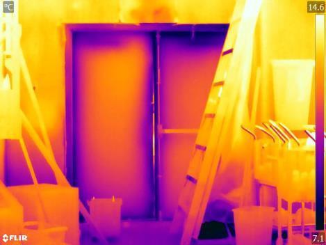
5 Back Door 2 Visual


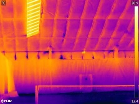
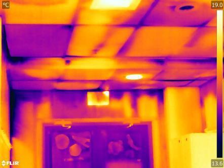
6 Water can be seen in the ceiling above the back door that is in between the court groups. This would indicate there are holes in the roof that would allow cold air to infiltrate into the building.


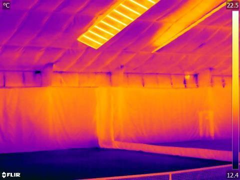
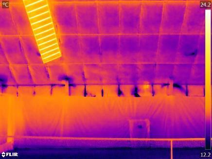
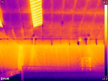
7 Court 6: In court 6 cold air can be seen infiltrating into the building through the seams between the insulation

8 Court 6 Side Wall

9 Court 6 Side Wall


10 Court 6 Far Wall On the far wall of court 6 you can see air infiltrating into the building through the insulation seams


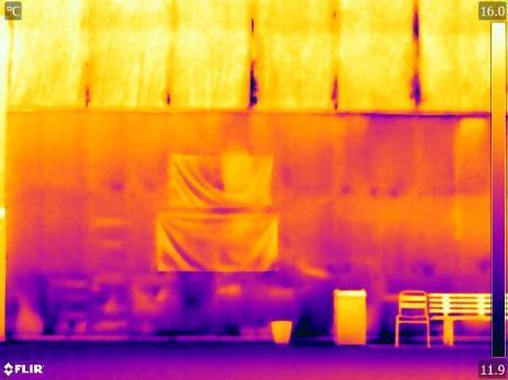
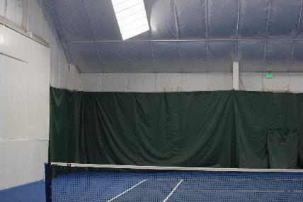
11 Court 4: Court 4 Far Wall 1 Visual

12 Court 4 Far wall 2 Visual

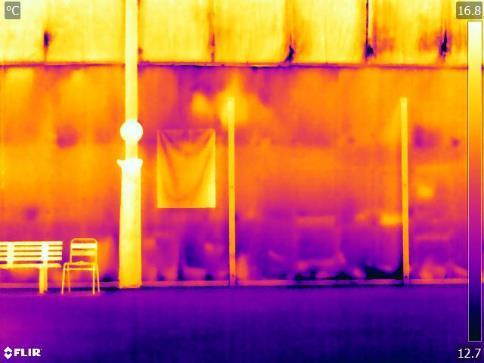
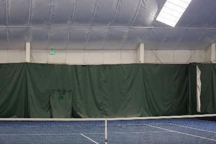
13 Court 2 Court 2 Far Wall 1

14 Court 2 Far Wall 2

15 Court 1 Court 1 Far Wall 1

16 Court 1 Far Wall 2

17 Court 3 Court 3 Far Wall 1

18 Court 3 Far Wall 2


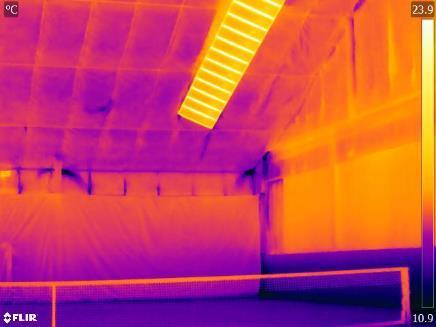
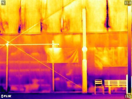
19 Court 5 Court 5 Side wall: On the side wall of court five air is seen infiltrating into the building through the seams of the insulation.

20 Court 5 Side Wall 2

21 Court 5 Side Wall 3

22 Court 5 Far Wall 1

23 Court 5 Far Wall 2


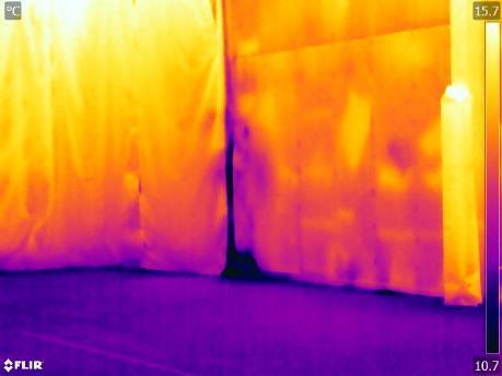
24 Court 5 Far Wall behind Curtain In court five behind the curtains more water damage was discovered. Cold air is also infiltrating into the building through the seams of the insulation.

25 Weight Room Far Wall Door


26 Weight room On the outdoors side of the weight room you can see the warm air exfiltrating from the building near the flashing.


27 Outside Vents Both of the large shutter vents hot air can be seen exfiltrating to the outdoors. Vent on the 695 Side


28 Additional Thermal Images Left Side of Courts Panoramic View Right Side Courts Panoramic View
29 ENERGY METHODOLGY The science of thermography involves characterizing the temperature of a surface by interpreting its infrared radiation patterns. This is accomplished through remote, nondestructive measurement utilizing thermal imaging. The temperature patterns of the surface represent a collective response of all the components to absorb, emit, transmit and reflect Infrared Radiation creating an IR reaction on the surface being viewed. In turn, by monitoring the surface utilizing thermography, thermal differences can be a result of both surface and subsurface changes. Depending on the findings, conclusions may be drawn that indicate how well the building is functioning in regard to energy concerns. This conceptual simplicity often overshadows the fact that the technology involved is complex and its proper application takes special knowledge acquired through years of experience. What s the best equipment to use? How do you use it properly? How do you correctly interpret the image? What parameters do you use for diagnostic purposes and why? These questions shed light on the fact that practical thermography, including energy related thermographic evaluation of a structure, is a complex, multi-disciplinary occupational field, which requires 100% dedication and commitment to professional guidelines and practices. Infrared inspections are an excellent rapid assessment technique and the most accurate and effective method of determining the energy problems of a building, the severity of the problems, and solutions or corrective measures. Thermographic Inspections Provide: 1. Nondestructive Testing 2. Accurate and fast inspections that assist in qualifying energy problems such as: Air Infiltration Air Intrusion Air Exfiltration Insulation Voids Damaged Insulation Subsurface Moisture Leaky Ducts Defective Materials Poor Workmanship 3. Categorization of Deficiency Severity 4. Retrofit Prioritization Information 5. Quality Control Assistance 6. Energy Awareness
30 Professional assurance Hurley and Associates, Inc. (H&A) has performed this Non-destructive evaluation in compliance with industry standards as published through ASTM and ASNT. The results of this evaluation are strictly an interpretation of measurements as they relate to the proposal of services. H&A, Inc. is not responsible for any warranty, implied warranties or workmanship as it relates to the structure, object or device being inspected. Furthermore, H&A, Inc. offers non-destructive test and evaluation services and does not supply corrective action services, hence remaining unbiased by remedial contractual opportunities that result from these services. In turn H&A is not responsible for any verification of retrofit action as a result of this report. While this report will present findings as they relate to the concerns expressed, we do not suggest that the services rendered are the only method to successfully inspect and evaluate the structure, object or device. Additionally, while performing the inspections for the original concerns expressed other concerns related or otherwise may become apparent requiring additional tests to investigate further. These concerns if applicable will be addressed within the report along with appropriate follow-up measures within the capability and constraints of H&A. If there are measures of further evaluation needed that are not within the professional services offered by H&A, such services may be recommended but not endorsed. If requested H&A may provide referrals to professionals within the discipline of services requested, but makes no obligation to acquiring these services or results of such continued affiliations.