CombiSump. Sump pump
|
|
|
- Peregrine Golden
- 5 years ago
- Views:
Transcription


1 CombiSump Sump pump

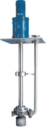
2 CombiSump Centrifugal sump pump CombiSump is the sump pump solution for thin liquids. The pump is part of Johnson Pump s Combi-system, a modular programme of single stage centrifugal pumps with a high degree of interchangeability of parts between the different pump constructions. The CombiSump is a range of centrifugal sump pumps, with the pump casing submerged into the liquid and a dry motor construction. The hydraulic parts of these submersible pumps consist of the pump casings and impellers of our CombiChem and CombiNorm pumps, its hydraulic field meeting ISO 2858/DIN and DIN Special executions meeting API 610 standards are optional to above standard executions. The pump is driven by a customer specified or standard IEC flange electric motor V1 placed on a lantern piece mounted on the base plate. The power is transmitted through a flexible coupling and an intermediate shaft. The pump casings pressure flange is connected to a discharge connection on the base plate. CombiSump Benefits Available in several materials High pump efficiency Suited for a wide span of duties Easy maintenance Compact, space saving construction Low maintenance cost


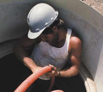
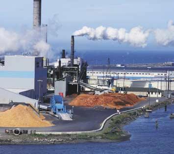
3 From know-how to finding solutions General industry CombiSump pumps can be used for all kinds of sump duties. Another known application is pumping cooling water when river or lake water is used. Petrochemical industry CombiSump pumps are often used for draining waste water collecting basins. Typical process duties are e.g. drain pump or hydrocarbon condensate. Off Shore In Off Shore industries CombiSump pumps are used for several duties where it is desireable to have a dry motor construction.
4 Dry part Features and Electric motor mounted on a flange resting on supporting rods or lantern piece accurate alignment by means of adjusting bolts customer specified or standard IEC flange motor V1 Coupling standard fitted with elastic coupling optionally available with membrane coupling Bearing construction double-row angular-contact ball bearing for axial loads on the pump shaft. Delivery connection placed on the baseplate flanges according to ISO 7005 PN 16 flanges according to ANSI B lbs horizontal or vertical position possible Baseplate standard version is a rectangular plate round flange shaped plate is also possible can be adapted to the size of the pit according to customer specifications
5 benefits Column pipe situated below the baseplate consisting of one or more parts connects the pump casing with the baseplate protects the shaft supports the intermediate bearings if applicable sump depth according to customer specification Submersible part Slide bearings pump shaft provided with slide bearings number depending on the sump depth of the pump shaft can be provided with grease- or liquid lubrication Pump casing/impeller impeller design for low NPSH values pump casings available in cast iron and stainless steel impellers available in cast iron, bronze and stainless steel optimised hydraulic performance suitable for a wide range of liquids Delivery pipe on the baseplate side mounted to delivery connection mounted to delivery flange of the pump casing by means of bend
6 Bearing In the part below the baseplate (the 'wet' part) the pump shaft is provided with slide bearings. The number of slide bearings depends on the length of the pump shaft and the rotating speed. The slide bearings can be provided with grease- or liquid lubrication. The part above the baseplate (the 'dry' part) is provided with a double-row angular-contact ball bearing for the pump shaft. Shaft sealing At the location of the shaft passage the baseplate is provided with a shaft sealing. Standard this is an oil baffle. A mechanical seal or gland packing is also possible, for example to prevent harmful odours from emerging into the atmosphere.
7 Technical data Max. capacity 800 m 3 /h Max. head 160 m Max. working pressure 16 bar Max. temperature 160 C Max. speed 3600 rpm Performance overview H[m] H[m] Q[m 3 /h] Q[m 3 /h] 1500 rpm 3000 rpm H[m] H[m] Q[m 3 /h] Q[m 3 /h] 1800 rpm 3600 rpm Subject to alterations
8 Cape Town (Head Office) Physical Address : 48 Marconi Road Montague Gardens 7441 Postal Address : P.O.Box 519 Milnerton Cape Town 7435 Telephone : (+27) Fax : (+27) / info@southernpumps.co.za Johannesburg Physical Address : Unit 47, Sunnyrock Ind Park 5 Sunnyrock Close Sunnyrock Germiston Postal Address : P.O.Box Gardenview 2047 Telephone : (+27) Fax : (+27) jhb@southernpumps.co.za SOUTHERN PUMPS