Table of Contents 2. Structural Systems.4 Foundations.4 Floor System...4 Columns..5 Lateral System...5
|
|
|
- Shauna Garrison
- 5 years ago
- Views:
Transcription


1 WISCONSIN PLACE RESIDENTIAL TECHNICAL ASSIGNMENT 1 OCTOBER 5, 2007 KURT KRASAVAGE THE PENNSYLVANIA STATE UNIVERSITY STRUCTURAL OPTION FACULTY ADVISOR: DR. ALI MEMARI
2 Table of Contents Table of Contents 2 Executive Summary...3 Structural Systems.4 Foundations.4 Floor System...4 Columns..5 Lateral System...5 Codes and Code Requirements...6 Codes and References..6 Deflection Criteria 7 Materials..7 Gravity and Lateral Loads.8 Dead..8 Live.9 Lateral Loads...9 Wind..9 Seismic 15 Conclusion 17 Appendix A. Dead Loads 18 B. Seismic Analysis.21 C. Spot Checks..22 Page 2
3 Executive Summary Wisconsin Place Residential consists of 15 above stories and 2 below grade stories. The building is approximately 479,000 SF, stretching from 25 feet below grade to 142 feet above grade. The building consists of 432 units spread out over the 15 floors. The 13 th floor contains a 1,000 SF pool for all tenants of the building. The two levels below grade are set aside for residential parking and are integrated with the parking for the mixed use development. This report introduces the structural conditions throughout a detailed description of the foundation, floor system, columns, and lateral systems. A preliminary analysis of seismic and wind lateral forces was researched along with spot checks of typical floor framing elements in gravity load areas as well as a simplified check of a typical shear wall. ASCE 7 05 was used to determine all wind and seismic loads. The wind analysis was computed using the analytical procedure and the seismic design loads were computed using the equivalent lateral force procedure. After completing the seismic and wind analysis I found the maximum base shear of the building to be controlled by the wind in the N S direction (770 kips) and the maximum moment due to the seismic loads to control (67,171 ft kips). The seismic forces distributed throughout the floors produced the largest force into the slabs (89 kips). Even though the seismic produced the largest forces overall, the wind produced much higher forces in the lower levels and gradually increased to the top of the building, whereas the seismic forces were low at the lower levels. All of these results are a preliminary analysis to gain a basic understanding of what is happening with the structure of the building and how the lateral forces are distributed throughout the floors. Page 3
4 Structural Systems Foundations The foundation shall be supported on spread footings. Column and wall footings supported by rock shall be designed for a bearing pressure of 40,000 PSF. A 4 inch gravel base shall be provided below floor slabs as a moisture barrier. Also, under floor sub drainage system shall be installed. All exterior footings shall be a minimum of 2 6 below grade. All controlled compacted fill shall be compacted to not less than 95% of the maximum dry density determined in accordance with ASTM D 698. Floor Systems 1 st Floor: Slab on grade. 2 nd 12 th Floor: Flat plate 7 ½ thick unbounded post tension slabs, with a two way bottom reinforcement mat of #4@24 continuous bars each way. Hooked bars at discontinuous ends are provided along with 2 #5 top and bottom additional bars along free slab edges. Concrete for slabs shall be normal weight concrete at 5000 psi. The post tension cables consist of uniform tendons being pulled in the S N direction and the banded tendons are in the pulled in the W E direction of the building. The typical uniform cables are 15.0 klf and the banded cables range from approximately kips. 13 th Floor: Floors are typically post tensioned the same as the 2 nd 12 th except in the pool area. The 12 and 15 slab areas require #5@24 O.C. each way continuous on top and bottom. The 23 slab area requires #6@12 O.C. each way continuous on top and bottom. Page 4
5 Pool House Roof: 7 slab with normal weight concrete and 60,000 psi reinforcing steel. A top and bottom mat of #4@12 O.C. continuous each way is required. Additional top reinforcing for column and middle strips is 6#5 top bars. 14 th and 15 th Floors: Floors are typically post tensioned the same as the 2 nd 12 th. Main Roof: Slab is 8 thick unbounded post tensioned with a two way bottom reinforcement of #4@24 continuous each way. For the 10 and 12 thick areas, #5@24 continuous mats are required as well as 2 #6 top and bottom additional bars along free slab edges. Columns The columns in Wisconsin Place Residential are primarily standard reinforced concrete with varying sizes, shape, and reinforcement depending on their location and loads that are applied throughout the building. The most typical shapes are 16 x28 and 16 x32. The reinforcement for the columns varies from floor to floor. The typical reinforcement is 8#7 or 8#8 bars, but varies throughout typical levels. The 12 th 13 th floor reinforcement is typically #10 or #11 bars, due to the fact that they are supporting the pool. The loads vary greatly from column to column and are as large as 1380k and as small as 122k for dead loads and 293k to 17k for live loads at the top of the pad. Lateral System Concrete shear walls make up the buildings lateral load resisting system. Two elevator cores serve as the main components of these elements and are connected from the 1 st Floor to the roof. There are also three other shear walls spread out on the west side of the building. Typically the shear wall Page 5


6 reinforcement is for horizontal reinforcement and #6 or #7 bars for vertical reinforcement. The typical reinforcement for ties and crossties cooresponds to the maximum spacing for columns. Codes and Code Requirements Codes Used for the building The structural design of Wisconsin Place Residential used various codes for gravity and lateral load conditions. Some of the codes used are the ACI Building Code Requirements for Structural Concrete, ASCE 7 02, and the 2003 International Building Code. Codes Used for this Report All of the information that I computed throughout this report took in consideration the most up to date codes. ACI , ASCE 7 05, and the 2006 IBC. Also I referenced the Design of Concrete Structures 13 th edition by Nilson, Darwin, and Dolan for structural designs. Page 6
7 Deflection Criteria Maximum deflection of studs in exterior walls subject to wind shall be L/600 when used as a backup for masonry. For other materials, maximum deflection shall be L/360. Floor deck deflection shall not exceed L/360 under full live and superimposed loads. Dead load and a 20 PSF construction live load, shall not exceed L/180. Materials Concrete: a. Formed Slab and Beams 5000psi b. Columns & Shear Walls (1 st 6 th ) 6000psi Columns & Shear Walls (6 th Roof) 5000psi c. Concrete Topping on Metal Deck 3500psi d. Walls and Piers 4000psi e. Pea Gravel Concrete (Grout) 2500psi f. All Other Concrete 3000psi Reinforcing Steel: a. Rebar Steel ASTM A615, Grade 60 b. Welded Wire Fabric ASTM A 185 c. Reinforcing Bar Mats ASTM A 184 d. Reinforcing bars in Balconies ASTM A 775 Metal Deck a. Welding at Supports 5/8 Diameter puddle welds at alternate ribs b. Floor Deck 2 Deep and a minimum of 20 Gage Steel Page 7
8 Masonry a. Concrete Block ASTM C 90 b. Brick ASTM C 62 & ASTMC 216 c. Mortar ASTM C270 Gravity and Lateral Loads The gravity and lateral loads were determined in accordance with ASCE Live Loads were established using section 4 of ASCE General assumptions for dead loads were made based on unit weights from ASCE Instead of calculating every column and wall, I assumed an addition 10 PSF load on each floor. Dead Loads: Construction Dead Loads: Concrete 150 PCF Superimposed Dead Loads: Partitions 20PSF Finishes & Miscellaneous 5 PSF MEP 10 PSF Columns & Walls 10 PSF Shear Walls (SEE APPENDIX A) Page 8
9 Live Loads: Floors Including Partition Load Canopy Slab On Grade Storage Public Rooms and Corridors Balconies Lobby, Corridors, Stairs and Pool Areas Penthouse, Mechanical Room Elevator Machine Room Roof Roof Snow Load 60 PSF 75 PSF 100 PSF 125 PSF 100 PSF 100 PSF 100 PSF 150 PSF 125 PSF 30 PSF 27 PSF Lateral Loads A summary of both wind and seismic load analyses are in the following section. Please refer to Appendices A and B for a more detailed description of wind and seismic procedures. Wind Wind loads were analyzed using section 6 of ASCE For ease of the analysis I assumed the building to be a rectangle instead of a U shape. I also ignored the cut backs in different elevations of the building because they only occurred on one side of the U shape. Therefore the wind would still be affecting either the East or West side regardless. I also did not take in consideration the Penthouse above the Main Roof or the canopy, because it would contribute minimally. The building also had many curves and undulations, so I assumed them to be straight. As you can see in the picture below of my actual building floor plan, there is a court yard formed within the U shape. Please note that if a wind tunnel test was Page 9
10 performed the cladding report would most likely show higher wind pressures on the South Elevation of the building because the legs of the U would act like a funnel, thus causing higher wind speeds which would increase pressures. Another assumption I made was that throughout my calculations I took the worst case of the K z factor that applied to each floor because there were as many as three different K z factors applying to each level and I was being conservative. Page 10
11 Typical Floor Plan W S E N Shear Walls A A Page 11
12 Building Section A A Page 12
 90 N S Length of Building 240 E W Length of Building 296 No. of Stories 15 Typ. Story Height (ft) 9.21 Building Height (ft) 141.23 L/B in N S Direction 0.")
13 Factors Used in Wind Distribution Spread Sheet Approximate Fundamental Period Topographic Factor K zt 1 Wind Directionality Factor K d 0.85 Basic Wind Speed V (mph) 90 N S Length of Building 240 E W Length of Building 296 No. of Stories 15 Typ. Story Height (ft) 9.21 Building Height (ft) L/B in N S Direction 0.81 L/B in E W Direction 1.23 h/l in N S Direction h/l in E W Direction C p, windward C p, leeward C p, side wall Gust Factor N S Direction E W Direction Page 13
14 Page 14
15 Seismic W eight of the Building Floor Net Floor Area L oads Weight of Shear Walls ( kips) Total Dead Lo ad (excluding (SF) (PSF) Shear Walls) (kips) (kips) Dead Load 2 22, ,195 3, , ,241 4, , ,240 4, , ,670 5, , ,670 5, , ,670 5, , ,626 4, , ,583 4, , ,584 4, , ,584 4, , ,584 4, , ,243 3, , , ,527 3, , ,527 3,641 Roof 25, ,679 3,737 Sum 473, ,206 67,790 Page 15
16 Factors Used in Seismic Distribution Spread Sheet Seismic Distribution Page 16
17 Conclusion After completing the seismic and wind analysis I found the maximum base shear of the building to be controlled by the wind in the N S direction (770 kips) and the maximum moment due to the seismic loads to control (67,171 ft kips). The seismic forces distributed throughout the floors produced the largest force into the slabs (89 kips). Even though the seismic produced the largest forces overall, the wind produced much higher forces in the lower levels and gradually increased to the top of the building, whereas the seismic forces were low at the lower levels. I was very surprised that the wind controlled over seismic, because the building is so heavy. All of these results are a preliminary analysis to gain a basic understand of what is going on with the structure of the building and how the lateral forces are distributed throughout the floors. Page 17
18 Appendix A Page 18
19 Page 19
20 Page 20

21 Appendix B Page 21
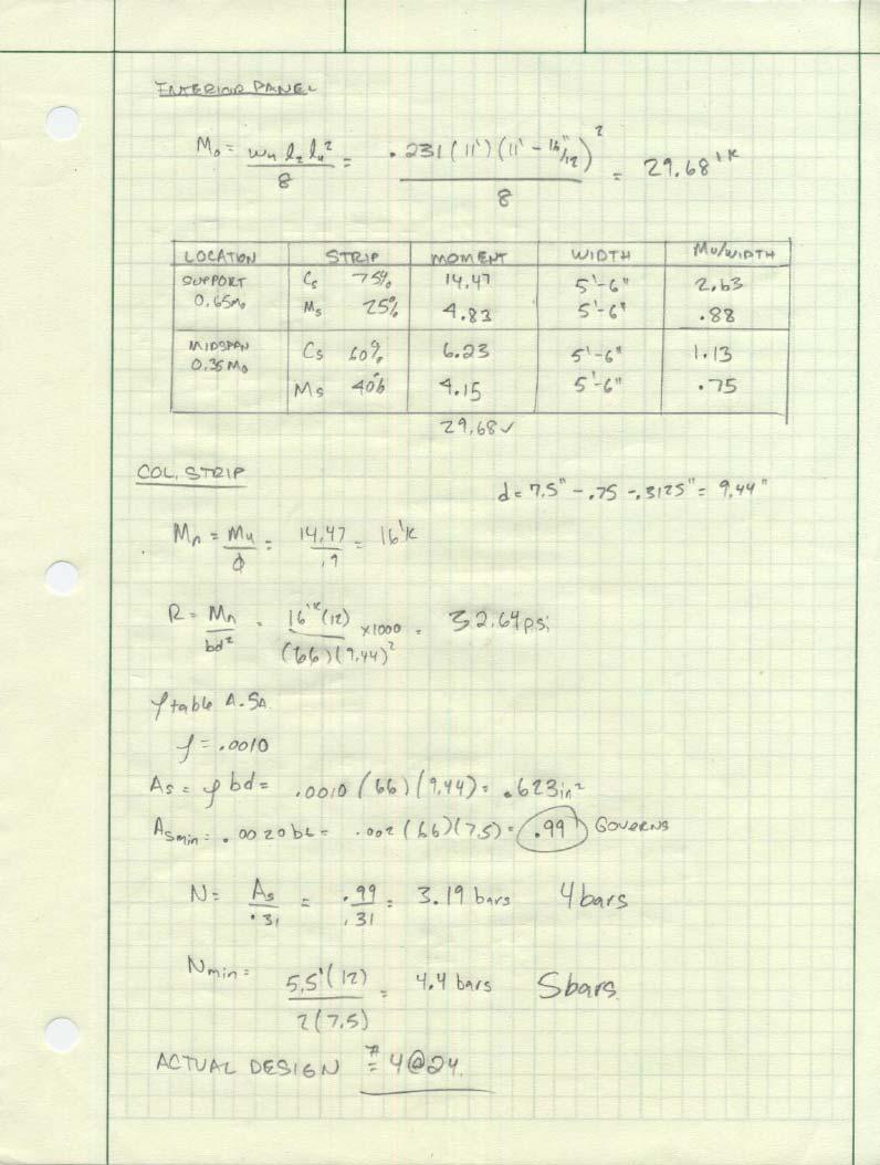
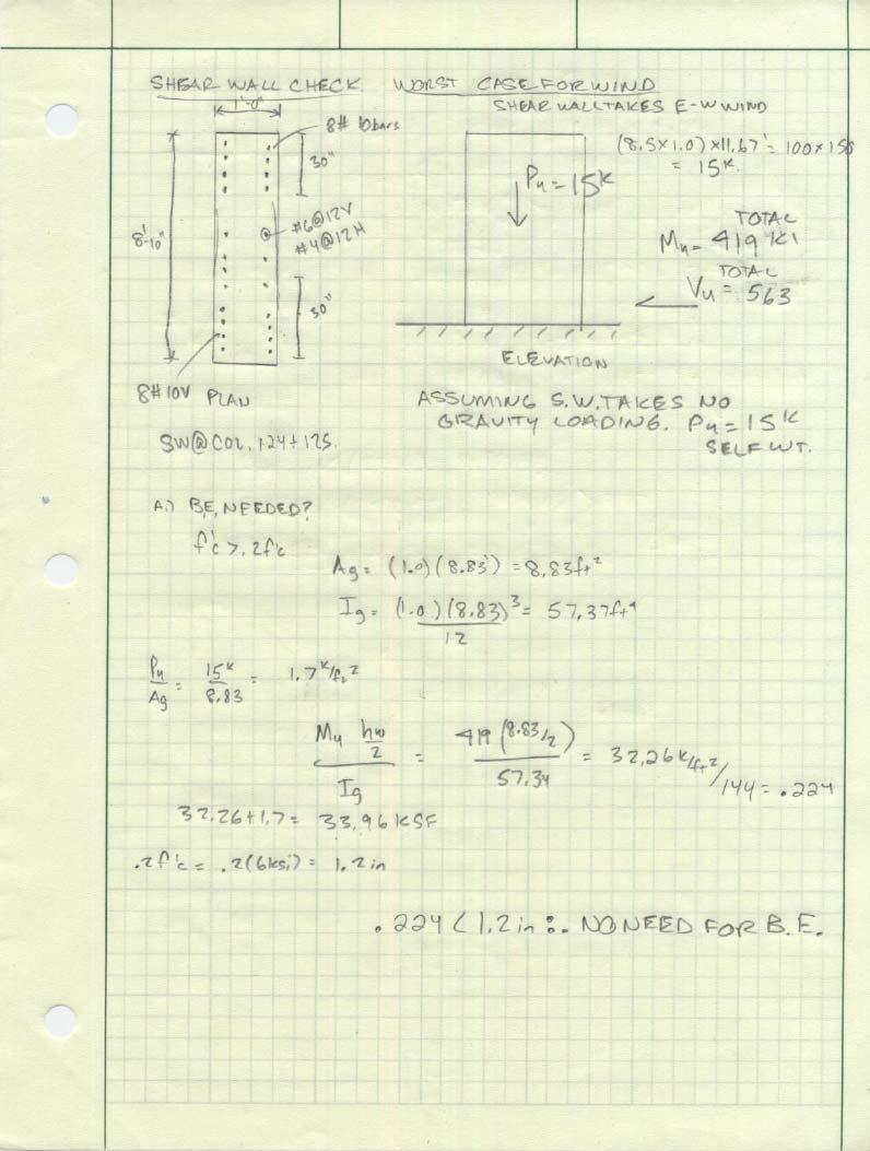
22 Appendix C Page 22
23 Page 23
24 Page 24
25 Page 25
26 Page 26
27 Page 27
28 Page 28