Life Cycle Mechanical Integrity Of Piping Systems
|
|
|
- William Hancock
- 5 years ago
- Views:
Transcription
1 Life Cycle Mechanical Integrity Of Piping Systems by Gerald H. May, PE
2 TABLE OF CONTENTS Life Cycle Mechanical Integrity of Piping Systems 1.0 INTRODUCTION 2.0 MECHANICAL INTEGRITY 2.1 Mechanical Integrity Definition 2.2 Elements of Piping Mechanical Integrity 2.3 Laws of Piping Mechanical Integrity Documentation 3.0 INTERRELATIONSHIP OF PIPE AND PIPE SUPPORTS 4.0 VISUAL OBSERVATIONS 4.1 Pipe Support Observations 4.2 Pipe Observations 5.0 NDE AND METALLURGICAL EVALUATIONS 6.0 EVALUATIONS 7.0 RECOMMENDATIONS 7.1 Short Term Recommendations 7.2 Long Term Recommendations 8.0 SUMMARY Copyright 2012 Gerald May, PE Page 2 of 37
3 1.0 INTRODUCTION Life Cycle Mechanical Integrity of Piping Systems Piping systems in industrial facilities are usually the least maintained pieces of mechanical equipment in the plant. Pumps, compressors, turbines, heat exchangers, boilers, and condensers all have components that are known to need periodic inspection and maintenance. In many people s minds, Pipe is just there -- until something goes wrong. Except for unexpected dynamic loads, there are usually plenty of warning signs that there is a problem long before a catastrophic failure occurs. This course describes how to 1. Set up and implement a visual monitoring program, 2. Evidence to look for 3. Set up and implement a long term Non Destructive Examination (NDE) and metallurgical evaluation program 4. Document results and recommendations This through wall failure of a high temperature steam line luckily did not cause any injuries, but it took several hundred MWe off the power grid during the hottest part of the summer. A strong contributing cause of the failure was malfunctioning pipe supports. The purpose of any Mechanical Integrity program is to find developing problems before they become major failures that can injure people, and/or cause forced downtime. A successful program has several attributes: The program continues through change of personnel and management Information is retrievable to allow informed decision making Recommendations are revised or confirmed after each significant activity. Copyright 2012 Gerald May, PE Page 3 of 37
4 Disposition of recommendations are fully documented for a complete history of a piping system s repairs and inspection. Screening and sampling techniques are used to focus resources on the highest risk locations. There are three other courses in the Suncam library that are related to this work: 1. Introduction to Piping Engineering describes the basic design process, potential failure modes and design engineering calculations to engineer a piping system. 2. Pipe Support Failures provides good and bad examples of installed pipe supports with an emphasis on problems to avoid. 3. Building Mechanical Integrity Programs Into New Plants describes considerations in developing a Mechanical Integrity program during the design of new plant. Information described in these other courses will not be repeated herein. For failure modes of pipe, see Reference 1 For details of pipe support problems, see Reference 2. For developing Risk-Consequence charts, and selecting the piping systems to be included in an MI program, see reference 3. This course does tie all of these concepts together to provide an overview of how all this information interrelates. Copyright 2012 Gerald May, PE Page 4 of 37
5 2.0 MECHANICAL INTEGRITY OVERVIEW 2.1 Mechanical Integrity Definition Mechanical Integrity (MI) of piping systems has many different definitions. For this course: MECHANICAL INTEGRITY IS THE PROCESS TO ASSURE THE PIPE IS IN SATISFACTORY CONDITION FOR CONTINUED SAFE AND RELIABLE OPERATION. When analyzing this definition, it is apparent that clarifications are needed for some of the terms. SATISFACTORY CONDITION could mean: Complies With Original Code Requirements Verified Satisfactory Per A Fitness - For - Service (FFS) Criteria, Such As API 570 Operational For A Period Of Time Until The Next Scheduled Shutdown Operational Until The Next Recommended Evaluation. SAFE OPERATION could mean: Safety To Plant Personnel Safety To Personnel Outside The Fence Environmental Safety Safety To Shareholder s Investment RELIABLE OPERATION could mean: Full operation for a specified period of time Plant is available for immediate re-start at any time Piping system has sufficient by-passes that operation can continue even if maintenance is required Partial operation for a specified period of time Copyright 2012 Gerald May, PE Page 5 of 37
6 These clarifications are owner prerogative, and the exact clarifications that are set will have an effect on the number of piping systems included in MI, and the types and frequency of inspections to be performed. The actual process of MI remains nearly the same in all cases. Sometimes when working with these kinds of definitions, the discussion can become theoretical and lose a sense of reality. It is always good to think of MI in very personal terms, since that is how the plant personnel will relate to the program and what they will consider important. WHAT WILL IT TAKE FOR ME TO BE SAFE STANDING NEXT TO THIS PIPE? Viewed this way, the clarifications of SAFE, RELIABLE & SATISFACTORY become focused on what can go wrong, and what are the consequences. 2.2 Elements of Piping Mechanical Integrity To determine the condition of a piping system, the following elements are included: Design Basis Design operating conditions (thermal, weight, seismic, upset, wind, etc.), pipe sizes and material, dimensioned routing, pipe support designs, pipe stress calculations Baseline Condition- Preferably the known condition of the pipe and pipe supports at commissioning, but if unavailable, then based upon the first available inspection. If the baseline condition does not match the Design Basis, then a revised pipe stress calculation should be performed to match the actual installation. History of Operation Hours of operation, maximum temperature and pressure, flow rates, unusual operational conditions, known upset conditions History of Inspections Condition of pipe, pipe supports, insulation and connecting equipment based upon visual, NDE and metallurgical evaluations History of Maintenance Repair or replacement of any components; Adjustment, repair or replacement of any pipe supports; Repair or replacement of insulation; Repair or adjustment of end point equipment such as pumps that caused some change in pipe performance. Copyright 2012 Gerald May, PE Page 6 of 37
7 Long Term Recommendations After each inspection, unusual event, or other significant activity affecting the piping system, recommendations for inspection intervals, types of inspection, re-design, repair or adjustment shall be reviewed and updated as appropriate. If for some reason recommendations are deferred, then overall recommendations should be reviewed and revised as appropriate. 2.3 Laws of Mechanical Integrity Documentation In performing Mechanical Integrity evaluations, there is a constant review of previously generated data to determine what has changed. When the data is not complete or inaccurate, there are results that happen with such regularity, that they can actually be considered THE 3 LAWS OF MECHANICAL INTEGRITY DOCUMENTATION 1. IF AN INSPECTION IS NOT PROPERLY DOCUMENTED, THEN FOR ALL PRACTICAL PURPOSES, THE INSPECTION WAS NEVER PERFORMED. Corollary: If information is not properly stored, it will not exist long. 2. THE LESS INFORMATION AVAILABLE WHEN A PROBLEM IS FOUND, THE MORE ASSUMPTIONS THAT MUST BE MADE. Corollary: Risk increases unless conservative assumptions are made. Copyright 2012 Gerald May, PE Page 7 of 37
8 3. THE LESS INFORMATION AVAILABLE, THE MORE COSTLY THE PROCESS TO DEFINE A SOLUTION; OR THE MORE COSTLY THE SOLUTION WILL BE. Corollary: Management will be frustrated with unplanned costs and lost revenue. To understand these laws, consider a simple inspection of pipe wall thickness for erosion or corrosion. OBSERVATION: An inspection is performed after 5 years of service, and the minimum measured wall thickness is 90% of the nominal specified wall thickness. Scenario 1: This is the first inspection of the pipe since start-up and there was no baseline thickness data taken at that time. If 10% of the wall thickness has been lost in 5 years, then there is real concern of rapid thinning. Even though replacement is not required until minimum wall thickness is less than 75% of nominal, another inspection is required in less than 5 years. The scope of the inspection will be expanded to assure the condition of other areas of the piping system. Scenario 1a: Same as 1, except there was baseline data taken, but it cannot be found. The result is the same as if the data were never taken. Scenario 1b: Baseline data was taken and found, but the report is not clear on where the data was taken and the value of the measurements. All that is found is a statement in the commissioning report stating, Minimum measured wall thicknesses was 90% of the specified nominal thickness. While there might be some consideration to assume the minimum wall thickness data was taken at the same location as the 5 year data, the conservative assumption is to admit that the original data cannot be correlated, and to set re-inspections the same as Scenario 1. Scenario 2: There is well documented baseline data and it shows that there has been basically no change in thickness since commissioning at the exact locations inspected after 5 years. Next Copyright 2012 Gerald May, PE Page 8 of 37
9 inspection will probably be put off for 10 years and will be expected to be a minimal confirming inspection. Scenario 3: Same setup, except the fluid is highly toxic and there is a requirement that the pipe meet 85% of original nominal specifications. If the baseline data is non-existent or not well documented, then a nearly immediate repair or replacement program may have to be initiated. Copyright 2012 Gerald May, PE Page 9 of 37


10 3.0 INTERRELATIONSHIP OF PIPE AND PIPE SUPPORTS In other piping courses, the system concept has been stressed. A piping system should always be considered from equipment to equipment, including pipe, in-line components such as valves & flow meters, pipe supports, and equipment nozzles. This system approach is also true in a piping MI program. All of the components should be included, because there is an interrelationship of symptoms (observations of defects) and root cause(s). Without considering the entire system as a whole, evaluations may not be performed properly. EVALUATION RULE 1: AN OBSERVATION MAY BE THE PROBLEM, OR IT MAY EXHIBIT THE SYMPTOM OF ANOTHER PROBLEM IN THE PIPING SYSTEM. Just as with rotating equipment or other major mechanical equipment, seeing a damaged or broken part is usually not the complete story. A root cause analysis is typically performed to determine why the part failed. For most pipe observations, this is not a major exercise. Many times just completing the visual walk down of a piping system, reviewing a pipe stress analysis or maybe talking to an Operations or Maintenance manager may provide all the information necessary to be confident of the root cause(s). An example of Rule 1 is this variable spring hanger with the pipe clamp broken and completely disconnected from the pipe. The clamp should be on the pipe where the insulation is separated (white). The clamp was apparently on the pipe once, and is badly bent and above the pipe by 6. Pipe Clamp off pipe Copyright 2012 Gerald May, PE Page 10 of 37
11 1. This could be a poorly designed or poorly installed pipe support with a faulty clamp. If the support is the root cause of the problem, the failure of the support causes higher stress in the pipe, excessive sagging of the pipe, and potentially failure of other pipe supports since the load must be picked up by the adjacent pipe supports. 2. The second possibility is that the pipe support was properly designed and installed, but it has still failed. If this is the case, the support has been over loaded to failure because some other unexpected event happened to the pipe. A partial list of possible root causes is: a. This or other pipe supports malfunctioned, including bottomed out or topped out spring hangers b. Unusual operating event caused a high dynamic load c. Interference of the pipe with other equipment created high loads on this pipe support d. Field modification to the pipe increased load at this support e. Temporary loading by craft personnel, such as pulling against with a come-along or chain fall. f. Pipe, insulation and in-line components modified in the field to increase the load on the pipe support g. Pipe installed different thickness or diameter than design, increasing load on the support EVALUATION RULE 2: DAMAGE THAT LEADS TO FAILURE IS ALMOST ALWAYS VISUALLY OBSERVABLE LONG BEFORE THE ACTUAL PIPE THROUGH WALL FAILURE; PROVIDING TIME TO EVALUATE, THEN REPAIR OR REPLACE PIPE PRIOR TO FAILURE. Piping failures are typically from fatigue, corrosion, erosion, and long term material degradation (such as creep or embrittlement). Even when a pipe is severely damaged, often it does not fail through wall for a period of time. This means that annual visual observations can be highly beneficial to the safety and availability of a typical plant. Copyright 2012 Gerald May, PE Page 11 of 37

12 There are two important counter examples to visual symptoms appear before failure. 1. High temperature seam welded pipe may fail due to creep or creep-fatigue. If there is a piping system operating in the creep temperature range that is seam welded rather than seamless, it is susceptible to creep degradation in the seam weld and may fail catastrophically. With seam weld damage, the visual inspection may provide little or no forewarning. Based upon current industry understanding, the only reliable method is to inspect periodically to determine if the material is developing cracks in the seam weld. Special consideration should be provided to any high temperature seam welded pipe. Catastrophic failure of a seam welded high temperature steam pipe, which killed 6 workers. Copyright 2012 Gerald May, PE Page 12 of 37
13 2. The other major exception to the slow to failure of piping systems is a large dynamic event that was not anticipated in design. It could be Flow induced vibration resulting in excessive movement in certain operating conditions Thrust force caused by sticking valves Hammering caused by flashing water to steam Seismic event Other unexpected operational issues. It should be standard practice at plants to visually observe the pipe and pipe supports after a significant unplanned event. Visually observable damage to pipe, pipe supports, steel, insulation, or other equipment could be an indication of significant damage that needs to be evaluated and repaired prior to re-starting the plant. Copyright 2012 Gerald May, PE Page 13 of 37
14 4.0 VISUAL OBSERVATIONS 4.1 Pipe Support Observations Life Cycle Mechanical Integrity of Piping Systems Pipe support observations provide a large amount of information for a minimal cost. Annual observations in the ambient and operating condition of the pipe supports on a piping system create a possibility to trend data and recognize significant changes quickly. There are three basic documents to perform the walkdown. 1. Isometric sketch shown the pipe support mark number and location of each support. See Figure 4.1 for an example. 2. Pipe Support Visual Inspection Checklist, Table Spreadsheet showing each pipe support design information and the ambient and operating readings. See Table 4.2 for an example. Using the checklist, Table 4.1 and the isometric sketch, Figure 4.1, view each pipe support. The best documentation is to complete one checklist for each support and provide one or more photos. If pipe support detail drawings are available, the top portion of the checklist can be completed prior to the visual inspection, except for the operating temperature which needs to be provided by the control room at the time of the observation. During the baseline inspection, confirm the nameplate data, if the nameplate can be read. Sketch any differences between the installation and design. Before leaving a plant, transfer all of the data to the spreadsheet and review for accuracy and any significant changes since the last observation. Review each photo to assure the observations match the photo. Any discrepancies should be verified by re-observing the support. Table 4.2 contains more than the minimum data required. The reason is that the load was measured and adjusted in 2006, and this table was used to document the results. There are the measured loads, as well as the travel settings before and after the adjustment. The comment column is used for additional clarification. It is assumed that if more detail is needed in the future, the detailed report from 2006 will be available. Copyright 2012 Gerald May, PE Page 14 of 37

15 Rigid Hanger Life Cycle Mechanical Integrity of Piping Systems Variable Spring Hanger Constant Support Hanger CRH-1 through CRH-10 are Hanger Mark Numbers. Fig. 4.1 Isometric sketch shows the pipe routing and location of all pipe supports. Different symbols are used for variable spring, constant support and rigid pipe supports. Copyright 2012 Gerald May, PE Page 15 of 37
16 Table 4.1 Pipe Support Visual Inspection Checklist Copyright 2012 Gerald May, PE Page 16 of 37


17 Table 4.2 Example of Pipe Support Documentation Copyright 2012 Gerald May, PE Page 17 of 37
18 The methodology to record data should be consistent at each observation. These should include: Method of reading a variable spring scale in inches, mm, load or percent. This may vary from support to support depending upon the visibility of the scale and the pipe support vendor. Method of reading a variable spring scale from the top or bottom of the indicator. Some of these indicators are up to 1 thick, and inconsistency in method can greatly affect the data. Method of reading a constant support travel indicator in percent, inches, mm or some other scale. Most manufacturers have a scale from 0 to 10 with 11 marks, and it is convenient to read to 1 decimal point, such as 3.3. Sometimes there is room for travel beyond the scale, and a reading of 10.5 or -1.0 is possible. The full range of 0 to 10 is supposed to match the total travel of the can, i.e. if 3 total travel, each mark is 0.3, if 20 total travel, each mark is 2.0. Lisega constant supports have a scale in inches or mm, and should typically be read by that method. Method of reading a constant support can travel indicator. The round indicators are typically read at the center. Some manufacturers include pointers and it should be read from the point. However, often these indicators are fragile and are bent, or worse fall off. Method of reading a constant support can load scale. Each type of constant support has an adjustment to preset the load. They are usually hard to find and see as they are often internal to the can. The load is supposed to be set in the factory. The scale states Each mark is x% and provides an arrow to show which way to adjust to increase or decrease the load. However, experience of load testing has shown that after years of operation, the set load may be 10% to 20% off design, and the percentage change per mark rarely matches the scale statement. While the scale reading provides an indication of the amount of load adjustment available, there is not necessarily a correlation with field data. If adjusting load, always test the actual load. Do not trust the load scale. Method of reading variable spring and constant support cans when the indicator is missing, or the scale is missing, or both. It is sometimes possible to estimate what the setting is, or at least state if the spring is floating, topped out or bottomed out. Often there is a scale on both sides of a can, and the reading is different by a significant percentage depending upon the side observed. In these cases, mark on the isometric or spreadsheet which side is used. Sometimes the scales are missing, or oriented in such a manner that they cannot be seen without special access. When possible to access, a new scale should be attached, or painted on the can for consistent readings. Copyright 2012 Gerald May, PE Page 18 of 37


19 Often it is difficult to observe a support during operation to read the scale properly. A camera with a good telephoto lens may be more accurate than a visual reading. During a shutdown or outage, there may be better access than normal, and the spring travel setting can be read more accurately. This difference in observation method should be noted to avoid misinterpreting data. Sometimes there are anomalies with the scale, such as installed upside down, or reattached or other problems. Note on the spreadsheet or the isometric to assure that the assumption used is consistent. A typical variable spring floor support can and label Load Flange Adjustment Collar, Screws up and down to adjust height of load flange and compression of spring. Travel and Load Scale: 0 to 2-1/2 on this size can. Also in pounds. Design cold position, white diamond, 1-1/2, 4046#. Design hot position, Red diamond, 2-1/ #. Thus design movement 0.56 down, cold to hot. Spring rate 800 #/in. Indicator Tab Normally read at bottom. In this case 2-3/8. (If read incorrectly from the top of indicator, 1-5/8 ) Copyright 2012 Gerald May, PE Page 19 of 37


20 Lisega F style variable spring hanger. Scale has both inch and mm marks. There is no indicator tab. It should be read from the top of the load plate inside the can. In this case it is at 66mm or about 2-5/8. Variable Spring Hangers have travel stops installed at the factory. With this vendor s design, each can has 4 travel stops, 2 on each side with stops limiting compression and tension. In can on right, 1 travel stop has been removed from the back side and is hanging loose below the can. The travel stops must be removed before operating the system. Note also on these types of cans, as the spring compresses, the indicator tab will move up, not down. Other vendors may use pins or other devices for travel stops. Copyright 2012 Gerald May, PE Page 20 of 37


21 A typical constant support can travel scale from 0 (same as T for Top) up to 10 (same as B for Bottom). Read at center of diamond, or 6.9. Red button is design hot location, 6.5, and white button is design cold (ambient) setting, 3.5. Actual topped out and bottomed out is when the indicator has locked into the curvature of the slot, yellow arrows. An old constant support can with a travel scale from 0 to 6. The indicator is a pin that can easily break off. It is recommended to paint the scale and scale numbers on a can when it is difficult to read or unusual. This will provide more consistency in later observations. A typical Lisega constant support hanger: Its internal mechanism is completely different than other manufacturers. When reading the travel scale, it is typically in inches or mm, 0.25 in photo. As with other constant support manufacturers there is a red and white mark for the ambient and hot design locations. Read from the center of the indicator bar. Client painted a yellow line to help, but unfortunately the pin may rotate with time. The silver scale to the right was by the vendor. Client added the yellow inch scale because it is more visible in a dark building. Copyright 2012 Gerald May, PE Page 21 of 37


22 Another manufacturer s constant support travel scale. The indicator is just a piece of metal attached to the lever arm, which is susceptible to bending or breaking off. Note the scale has no numbers and observer has to visualize the direction of movement to assure which end of the travel scale is 0. In this case, as the rod goes down, the lever arm and indicator go down, so topped is 0 at the top of the scale and 10 is bottomed at the bottom of the scale. Reading in photo is 0.0. With these types of indicators, it is almost impossible to determine where the actual topped out and bottomed out setting is since it is based on internal stops on the spring which are not visible. If there were cold and hot marks on the travel scale, they are not visible in this photo. A constant support showing one style of load adjustment Red arrow, load adjustment bolt Green arrow points to the load scale, facing down and painted over as typically found Load block moves as load bolt is adjusted, changing the length of the lever arm and changing the scale reading. Blue arrow Copyright 2012 Gerald May, PE Page 22 of 37


23 Another style constant support load scale shown by green arrow. Load bolt is behind scale, red arrow, and accessible only through the slot on the back side of the can, blue arrow. As noted, scale is difficult to read and adjustment accuracy is not reliable. Copyright 2012 Gerald May, PE Page 23 of 37

24 An example of a test set-up to measure the load on a variable spring hanger: The orange yokes and yellow hydraulic cylinders are arranged to unload the rod below the spring as the hydraulic cylinders are shortened, the load is transferred from the rod into the hydraulic cylinders. When the rod is unloaded, the force in the hydraulic cylinders times the area of the cylinders equals the load that the spring is carrying. This technique can be used to measure the initial observed load in a rigid rod, variable spring or constant support rod hanger. If load adjustment is needed, then adjustment and testing is repeated until the adjustment matches the recommended load. 4.2 Pipe Observations Table 4.3 is a checklist of observations to make on the pipe as observations are made on the pipe supports. Pipe observations should also be made in the ambient and operating conditions, as interferences with other equipment and other damage may only be apparent in one or the other condition. Typically there are not nearly as many observations on the pipe as pipe supports and in fact no anomalies may be observed on an entire system. It is recommended that any observations be marked on the isometric with photo documentation. Copyright 2012 Gerald May, PE Page 24 of 37
25 Table 4.3 Example Pipe Visual Inspection Checklist Copyright 2012 Gerald May, PE Page 25 of 37
26 5.0 NDE & METALLURGICAL EVALUATIONS Depending upon the piping system, Non Destructive Examination (NDE) and metallurgical evaluations may be performed on a planned schedule or on an ad hoc basis because of concern from the visual observations or operating history. Whenever inspections are performed it is extremely important to document, exactly which welds or pipe were inspected, the exact location, and the inspection results. One method is shown here. Create an overall isometric of the piping system, and then create inspection areas for the entire piping system. For each inspection area, create an inspection sketch that shows every known weld, with an identification number. If original pipe fabrication spool drawings are available, they can be used. All sketches should be 8-1/2 x 11 for ease of use in the field. See Figure 5.1 for an example inspection isometric showing the inspection areas. Figure 5.2 shows the details for an inspection area. Figure 5.1 Example Inspection Isometric Showing Inspection Areas Copyright 2012 Gerald May, PE Page 26 of 37
27 If the pipe is insulated, it is unlikely that the location of every weld is known. The numbering system and sketches should allow for additional welds. Types of welds that are commonly found after insulation is removed are: Shop girth welds Field girth welds created to make a fit-up Alignment dogs welded in the field for final fit-up. These are temporary welds near girth welds that were used for plates to help the pipe fitters align the pipe for the welder. They are typically removed, but often this removal is not complete and the weld remnants are the initiation point of cracks in the pipe. Radiographic plugs, installed in the pipe at girth welds to place the radioactive source inside the pipe to take radiographs. Plugs are then seal welded into the pipe approximately 6 from the girth welds. Plugged connections for instrumentation, sampling, flushing or other purposes. Insulation supports welded to pipe, particularly on riser pipe Figure 5.2 Example Of Inspection Sketch Showing The Location Of Each Weld In The Inspection Area. Copyright 2012 Gerald May, PE Page 27 of 37

28 For welds with well - defined locations, such as the upstream and downstream side of elbows, thermowells, flanges or at welding TEE s, the locations do not need to be dimensioned. However, for welds that are typically hidden by the insulation, the sketches should show the dimension from a location that is clearly visible through the insulation, such as an elbow, TEE or pipe support, as shown in Figure 5.2. This will allow re-inspection of a weld for the minimal cost of removing the insulation. Document all inspection locations with photographs. While detailed photos may be helpful, assure that there are some overviews that show enough other adjacent pipe and equipment that the weld location can be oriented visually in the field later. Before taking the photos, use paint marker to mark the weld identification on the pipe. This is helpful not only for relating the photograph later, but for the inspector who will not necessarily be familiar with all of the locations. General Photo that shows the orientation, some of the weld numbers, and even the exact replica locations With this general view and the weld numbers readable on the photos, there will be clear identification to any future observers of the orientation and location of the welds. Copyright 2012 Gerald May, PE Page 28 of 37

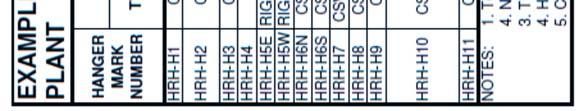
29 A photo of an insulation support ring installed on the pipe riser This photo has minimal value as there are no indications of the weld number, or even where it is on the riser. Inspectors should report their findings in detail on their corporate standard forms. These should include the method of inspection, weld identification number, calibration method, and detailed results of the inspection. NRI means No Recordable Indications and may be sufficient reporting. If there are indications, the inspector needs to be as clear as possible as to location of the defect around the pipe, and at what depth in the metal. This information should be transferred to the Inspection Summary and Disposition spreadsheet. See Table 5.1 for an example table. Each weld inspected should be noted with the results. If there are indications, the disposition portion needs to be completed noting if the indication has been repaired, or left as is or replaced. In Table 5.1, each weld is identified and the results from each inspection, no matter which year the inspection was performed. The old inspections are not erased. If there were indications, then the disposition is supposed to be described in the right hand column. On this piping system, inspections were performed on some welds in 1987 and 1988 before an overall weld numbering system was created. The reports were detailed enough that it was certain which welds were inspected and the results. Thus the 1987 and 1988 inspections are included, and the cross reference to the weld numbers shown. In Table 5.1 two locations have measured wall thicknesses less than specified minimum wall. There is nothing completed in the Disposition column, which leaves a question as to how serious of an issue this is. The Disposition should have been completed at least to say if the pipe is overstressed or not. One other interesting situation reported in Table 5.1. For welds HR2-1 O and HR2-1Q, one inspection reported the welds were stainless steel, which would make them dissimilar metal welds. These welds require shorter re-inspection intervals than same metal welds. However, in 2005, it was discovered the welds were not stainless steel. The controversy is not erased from the report, but maintained as the confusion may need a third confirmation at some point. Copyright 2012 Gerald May, PE Page 29 of 37
30 Table 5.1 Example of Inspection Disposition Report, note how lack of information in the Disposition column leaves a questions as to what should be done about the thin wall pipe. Copyright 2012 Gerald May, PE Page 30 of 37
31 6.0 EVALUATIONS Life Cycle Mechanical Integrity of Piping Systems All of the data described in Sections 4 and 5 is compiled to develop an evaluation of the current condition of the piping system. If reasonably possible, the evaluation should indicate the root cause(s) of any of the identified anomalies. In some cases, the root cause(s) cannot be easily identified. In these cases, the evaluation may not be completed. However, any necessary repairs or adjustments should still be performed. If the cause(s) of the damage is not known, then the reinspection interval may be shortened to assure potential repair issues are identified very early in their development to minimize cost of repairs, and to minimize any potential catastrophic damage. The evaluation tasks vary on each piping system and by what is observed. The personnel involved in the evaluation will vary depending upon the observations. At a minimum, the evaluation needs to be made by someone that understands piping systems, pipe supports and pipe stress. Other experts and operations and maintenance personnel may need to be involved in difficult cases. To provide guidance, the following goals and techniques should be considered in each evaluation case. 1. Determine if any observations are so serious that they need to be repaired immediately. If the piping system is operating, does it need to be taken out of service immediately? Some possibilities include: a. A through wall failure, or significant leak at a flange or fitting. b. Broken or non-functioning pipe supports c. Damaged welds that could propagate through wall d. Thinning pipe due to erosion or corrosion e. Damaged support steel f. Interference with other equipment that may damage that equipment, even if it does not damage this piping system. 2. Determine if any observations are so serious that they need to be repaired during the current outage if already shutdown, or during the next available shutdown. Possibilities include all of the #1 items, and: a. Poorly adjusted pipe supports that are bottomed out or topped out increasing pipe stresses b. Poorly performing pipe supports that should be load tested, travel adjusted or possibly replaced. c. Observations that indicate that pipe stresses may be significantly greater than design, and pipe inspections are needed. Copyright 2012 Gerald May, PE Page 31 of 37
32 d. Observations that the pipe is sagging, bowing or otherwise deformed. 3. Determine if pipe stress analysis needs to be revised because of the observations. 4. Determine if inspection intervals of welds should be revised to shorter intervals because damage has been observed, whether or not it was repaired. 5. Determine if inspection intervals of welds can be extended to longer intervals because damage has not been observed and there are no other observations that indicate damage. 6. Determine if additional inspections should be performed to confirm the extent of damage. This most often occurs when ultrasonic inspection shows some indication, and the extent of the indication may be confirmed and clarified by radiography, metallurgical replication, or perhaps a destructive examination from a boat or plug sample. 7. Determine if operational conditions can be modified to eliminate the potential problem. This may be a condition of operating at reduced pressure, temperature, or flow rate, modifying procedures to limit a vibration issue in some operational mode, or adding instrumentation to provide warning to the operators when a dangerous condition needs to be avoided. 8. Determine if maintenance procedures can be modified to correct a problem. 9. Determine if components should be replaced to avoid an observed problem. This could be a thicker pipe locally for high stresses, a different harder material to limit erosion, or a different material because of problems with dissimilar metal welds or high temperature. The ultimate goal of this evaluation is to completely clarify the root cause(s) of the observations, and correct them if possible. If that is not possible, modify inspections, maintenance procedures and operational procedures until confidence is gained on the condition of the pipe and how best to control the problems. Copyright 2012 Gerald May, PE Page 32 of 37
33 7.0 RECOMMENDATIONS 7.1 Short Term Recommendations Life Cycle Mechanical Integrity of Piping Systems The evaluation should lead directly to short term recommendations for repair, replacement, leave as is, inspect additional equipment or modify inspection intervals and methods. The short term recommendations may be based upon specific time frames for acceptable mechanical integrity until another event, such as an outage or shutdown. Time frames will be on a case by case basis. As with evaluations, every situation is a different. There may be multiple short term recommendations and some simple corrective actions may be attempted that are not successful. In those cases, follow-up recommendations are probably necessary. An example of such a situation is described below. EXAMPLE SHORT TERM RECOMMENDATION SEQUENCE: Pipe has been visually observed during a shutdown and several problems were observed in the spring supports. An evaluation of the pipe stress analysis indicates that with the observed bottomed out and topped out hangers, the pipe is probably over stressed at 2 branch connections. Short Term Recommendation 1. During the shutdown test the hangers and reset load and adjust travel as appropriate. Result 1: All but one of the supports was successfully adjusted. However, the load for one support could not be adjusted to the recommended load. Short Term Recommendation 1a: Determine if adjacent supports can be adjusted to account for the incorrect load. This is done by analysis first, and then by actual adjustment if the adjustment is theoretically possible. Result 1a: Adjustment of adjacent supports is theoretically possible, but cannot be achieved with the spring cans. Short Term Recommendation 1b: Determine if a replacement pipe support can be delivered and installed in time to not affect the outage. If not then, how soon thereafter. Result 1b: Order the replacement, but the delivery date may extend the outage. Short Term Recommendation 1c: Develop temporary work-arounds for operating the pipe before the new spring arrives, and a method to install the new support when it is on site. This could even be a recommendation to operate as is until the next scheduled shutdown. Copyright 2012 Gerald May, PE Page 33 of 37
34 Short Term Recommendation 2: During the shutdown, remove insulation, prepare and inspect welds in and around both of the branches that were calculated as over stressed. Result 2: Some damage is found that may be related to over stress condition. Recommendation 2a: Repair damaged welds and re-inspect until the welds are considered in good condition. Recommendation 2b: Expand the inspection to nearby welds to determine if the damage is local, or more widespread. Repair and re-inspect as needed. This example represents a typical fluid situation in which there is a limited time window to complete a MI study and make necessary repairs without affecting the shutdown time. The resolution is dependent upon the severity of the problems, the amount of time required for new parts, the cost of extending the outage, and other factors. This example points out the need for the general approach of performing inspections as early in an outage or shutdown as possible. Plan for potential repairs and be prepared to implement the plan if significant damage is found. Sometimes there is extreme pressure to let the piping system go back in service without completing repairs. In these cases, temporary modifications, operational controls and administrative controls may be necessary to control risk. Consider limiting access to area Consider installing limit stops or other devices on the pipe to assure it does not move excessively. Consider reducing operational temperature or pressure to reduce pipe stresses. Consider temporary patches on pipe to strengthen local areas in lieu of pipe replacement that cannot be achieved in time. Consider requiring short shutdowns periodically to inspect welds until the repairs can be performed properly. 7.2 Long Term Recommendations After short term recommendations are implemented, there should be a review of the Long Term Recommendations: As a minimum, the standard visual observation schedule should be maintained, although an accelerated schedule may be appropriate. An extra observation may be performed immediately after re-start to assure the pipe and pipe supports function properly after repairs and adjustments. Copyright 2012 Gerald May, PE Page 34 of 37
35 The Long Term Recommendations should be reviewed and updated in the Inspection Recommendations. All inspection intervals and types of inspections should be reconsidered. See Table 7.1 for an example table. If repairs were made to particular welds, it is common to recommend that these welds be re-inspected within 1 to 3 years to assure the repair is performing adequately, and the cause(s) of the damage have been eliminated. If no damage is found upon the re-inspection, the inspection interval can probably be returned to the standard interval for that piping system. Note that for most steels, 3 repairs over the same surface softens the metal and often leads to replacement of that section of pipe. Based upon analysis, and other damage observed or repaired, inspection schedule and type of inspections may be modified. It is also recognized that technology advances are continually improving the types of inspection that can be made. It is appropriate to improve the methods whenever new methods are proven. Based upon recent improvements in ultrasonic inspections and radiography, a couple of cautions are noted. 1. New methods will probably be more sensitive than previous methods, and it is common that indications are found that would not have been visible in the earlier methods. Be cautious not to over react and judge pipe has deteriorated, when the inspection method baseline has changed. 2. New methods are sometimes over sold by the inspectors, or perhaps not completely understood. Indications that are identified only with a new higher sensitivity inspection technique may be attributed to a particular damage mechanism, when it is actually caused by something else. An example is creep voids in the grain boundary in a computerized ultrasonic examination may look very similar to porosity or inclusions in a weld. While none of these situations are desirable. Porosity and inclusions are original weld defects, but if they are incorrectly called as creep voids, then major replacement programs may be implemented when unneeded. Copyright 2012 Gerald May, PE Page 35 of 37
36 Table 7.1 Example of Inspection Recommendations Report by Individual Weld Identification Numbers Copyright 2012 Gerald May, PE Page 36 of 37
37 8.0 SUMMARY 1. Mechanical Integrity is the process to assure the pipe is in satisfactory condition for continued safe and reliable operation. Exactly what is meant by satisfactory, safe and reliable must be defined by the Owner / Operator of a plant. 2. An alternative definition of Mechanical Integrity is What will it take for me to be safe standing next to this pipe? 3. Accurate complete documentation of the design, repairs, pipe support adjustments, inspections and operational history are highly important for proper evaluation of a pipe s condition. 4. When historical documentation is not available, assumptions must be made. The lack of data will force conservative assumptions, and likely higher costs to resolve any problem. 5. Virtually all observations of anomalies or damage may be the real problem, or they may be the symptom of another root cause. 6. Pipe is usually slow to fail, which makes visual observations and long term inspection programs a reasonable approach to Mechanical Integrity. There are two exceptions that the engineer needs to recognize in an MI program. a. A seam welded pipe operating in the creep range of the metal should always be inspected by NDE on a regular basis. Catastrophic failure can occur without visible symptoms. b. Any unusual operating experience that creates conditions outside the design basis, and particularly large dynamic loads should trigger at least a visual observation before re-starting the piping system. NDE may be appropriate. 7. Visual observations need to be performed based upon a consistent methodology and complete documentation. 8. NDE and metallurgical evaluations need to be documented completely as to results, and locations. 9. Any pipe support adjustments, pipe repairs or other disposition of observations need to be completely documented. 10. Upon completion of each cycle of observations, re-evaluate, and revise all Long Term Recommendations, as appropriate. Copyright 2012 Gerald May, PE Page 37 of 37