TECHNOLOGY. Hydromill
|
|
|
- Dora Blankenship
- 5 years ago
- Views:
Transcription


1 TECHNOLOGY Hydromill

2 Everywhere the diaphragm wall market is moving to higher and higher targets in terms of depth and verticality control. Metro stations, new foundations for residential and commercial areas, ports and dams construction and refurbishing are the most important projects in this scenario. Hydromill technology allows the construction of diaphragm wall in the most different soil conditions, guarantying the most accurate level of verticality control at drilling depth unattainable in the past. Soilmec design, manufacture a complete range of hydromill equipment facing all the possible market request. The continuous development with Trevi allows the new solutions coming from the job site experience. So this continuous synergy between Trevi and Soilmec put Trevi Group as a World Leader in the diaphragm wall market

3 Typical deviation from the vertical: 0.5 % Excavation beyond 200 m Excavation in rocks and soils with penetration high resistance Continuous wall guaranteed by various type of joints Panel thickness up 2000 mm
 and foundations.")

4 Technology Diaphragm walls are common practice in civil engineering as part of or as aids to the building of civil and hydraulic structures. Hence, they can be either temporary or permanent. In the realm of structural diaphragm walls a distinction exists between retaining structures (earth and hydraulic) and foundations. The walls, for hydraulic purpose, can be subdivided into impervious (cut off) and draining. Basically, a trench is excavated in the ground, generally in the presence of a stabilising fluid, then back-filled with an appropriate material. The trench geometry (width, depth and length) is designed according to the characteristics of the structure to be built; these geometrical features and also the ground conditions determine the choice of best suitable trenching equipment.
5 Construction stages PRIMARY PANELS PRIMARY PANELS PHASE 1 PRE-TRENCH PRIMARY PANELS Site preparation and guide wall construction operations are similar to the ones usually carried out when excavating a diaphragm wall by conventional grab. The work area must have bearing capacity of suitable for the construction equipment. The guide walls can be schematically realized as shown in the figure. Guide walls Guide walls are needed to ensure: a guide for the excavation and proper alignment of panels; the stability of the top of the trench; a support to the vertical loads generated by the reinforcement cages hanging above the guide wall. Pre-trench excavation The suction feeding pump of the hydromill is positioned above the milling drums. It shall be fully submerged in the slurry for suction to activate. This is why a pre-trench is excavated for a few metres, to ensure the pump above the milling drums is submerged. Pre-trench excavation is usually performed with slurries by means of a backhoe or cable grab mounted on another carrier. PHASE 2 1st BITE PHASE 3 2nd BITE PHASE 4 INTERMEDIATE BITE Excavation During excavation, the two milling drums should work on the same type of material as much as possible, whether natural soil or concrete. The primary panels are excavated in natural soil; then the intermediate or closing secondary panels are excavated between two primary panels in which concreting has already been performed. The standard width of a panel is 2.8 m,. When soil conditions and/or wall geometry allow for it, it is possible to realize longer primary panels in three consecutive steps - i.e. three excavations: left from 2.8 m; right from 2.8 m; central from 0.5 to 1.4 m; as a result, the total width of the primary panel is 6.1 or 7 m. The joints between panels are made of concrete to ensure higher water-tightness compared to the ones realized with grabs. While excavating the secondary panels, the milling drums cut a small portion of concrete on each adjacent primary panel, thus creating a rough and clean contact surface at the ends of the primary panels. The overlap on the primary panel is determined according to the depth to reach and estimated max deviations. An auxiliary crane is used to position the reinforcement cage into the trench filled with slurry. The cage must be suitably reinforced to avoid any deformations and fitted with spacers on the faces to ensure the designed concrete cover to reinforcement. PHASE 5 CAGE INSTALLATION PHASE 6 CONCRETING PHASE 1 PRE-TRENCH PHASE 2 1st BITE PHASE 3 2nd BITE PHASE 4 INTERMEDIATE BITE PHASE 5 CAGE INSTALLATION PHASE 6 CONCRETING SECONDARY PANELS SECONDARY PANELS PHASE 7 SECONDARY PRE-EXCAVATION PANELS PHASE 8 EXCAVATION PHASE 9 CAGE INSTALLATION PHASE 10 CONCRETING PHASE 7 PRE-EXCAVATION PHASE 8 EXCAVATION PHASE 9 CAGE INSTALLATION PHASE 10 CONCRETING


6 Technology sheet pipes primary excavation digging sheet piling removal installation of sheet piling with water stop digging and secondary panel primary panel and concreting secondary panel concreting Sheet piling With this method, a steel sheet pile is driven into the primary panel, before concrete is cast. After concreting has been completed, the concrete on the fronts of the panel takes on the shape of the sheet pile and a recess is created. When concrete has hardened enough to keep its shape, sheet piles are extracted. Afterward the secondary panel is excavated using a suitable tool to copy the recess of the primary panel and remove soil from this area. When concreting, concrete fills the recess and provides a good interlock between the panels. This technique allows for the insertion of plastic elements called water stops between the panels, in order to guarantee increased water tightness. The Milan joint Trevi Group has developed a special system during the works for the Milan Underground line 3 project in 1985, a system which has been called Milan joint because of its origin. The joint is built using a PVC pipe, connected to the primary panel cage. The bottom end of the pipe is closed by a holed cap so as to allow the bentonite slurry to flow in the tube thus preventing the walls of the tube from collapsing due to the pressure the concrete, rising up during the excavation, will exercise on the tube walls. After excavation of the secondary panels has been completed, a cleaner is mounted on the grab; the grab is then lowered and the cleaner breaks the wall of the PVC pipe. This way the concrete penetrates into the pipe s cross-section thus creating a waterproof joint.


.")
7 Construction stages Cage installation Properly positioning the reinforcement cage is crucial to avoid that they are affected when cutting part of the primary panels. To guide cage positioning, it is possible to use stop ends at the edges of the primary panel. In the event two cages have to be positioned in the same panel, it is possible to use a temporary template in the middle of the panel for improved accuracy in cage positioning. These elements will be removed during concreting. Concreting Concreting is performed by the Tremie method, using pipes of a length of about 2 m each, joined one another to reach the bottom of the hole. Concrete is then poured through the pipe. By continuing to pour concrete, the trench is filled from the bottom, and the bentonite slurry comes out of the trench mouth (the slurries are separated from concrete due to lower density). In case of very wide primary panels, it is advisable to use two pipes through which the trench is filled with concrete. When excavating the secondary panel, it is important to prevent the concrete poured in the primary panels from occupying the upper part of the pre-trench, because this would make it difficult for the hydromill to lower and reach the depth at which the slurry suction pump is activated. To this end, it is possible to use a short sheet stop end driven in place before concreting the primary panels.


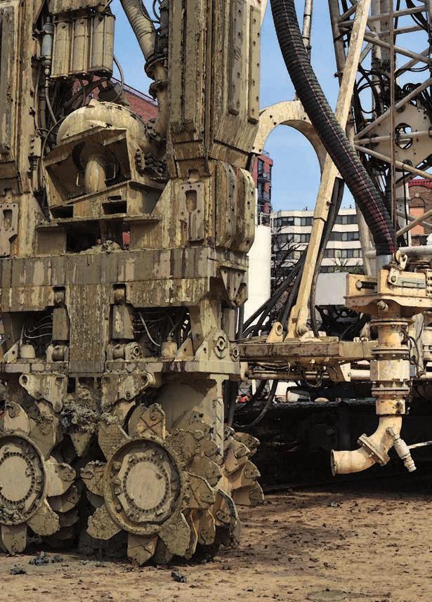
8 Job site logistics The hydromill system consists of three main pieces of equipment the milling unit, the carrier supporting it and the mud processing plant to treat the mud extracted from the excavation. The milling unit is made up of a steel frame onto which two independent counter-rotating milling drums are assembled. Milling drums with different torques and dimensions can be used to better suit the geometrical requirements. The milling unit is cable-suspended to the supporting crane s boom and controlled by means of a precision hydraulic system. The hydromill is progressively lowered into the trench; it excavates and crushes the soil or rock throughout the whole section of the trench. A submerged pump is positioned right above the milling drums. It triggers a circulation of the stabilizing fluid (bentonite/polymer slurry), which acts as a transport medium to evacuate the cuttings from the trench, and sends the mud mixed with cuttings to the mud treatment plant. This is where the cuttings are separated from the stabilizing fluid by means of vibrating screens, cyclones and eventually centrifuge depending particle size. Mud treatment system Bentonite preparation plant Auxiliary cranes Auxiliary cranes with grab Crane with Hydromill


9 Milling unit T-PANEL DEVICE Available for Tiger and Cougar ± 90 L Soilmec has designed all its modules with a rotation system conceived for T-panel execution or for other module orientations. This specific feature gives the possibility to facilitate the job site operations, leading to a reduction in terms of cost and time. Hydromill module SH-30 SH-40 SH-50 Body length (L) 10,5 m 13 m 14,7 m Weight 30 t 40 t 50 t Panel thickness 700/1200 mm 800/1800 mm 1000/2000 mm Panel width 2600/3000 mm 2800/3200 mm 2800/3200 mm Cutting unit torque ranges knm knm knm Module rotation system Standard Standard Standard Cutting unit H-9 H-11 / HH-11 HH-13 HH-15 Rated torque 93 knm 109 knm 131 knm 153 knm Drilling Speed 25 rpm 22 rpm 18 rpm 15 rpm Panel thickness mm mm mm SH-30 H-9 / H-11 HH-11* - SH-40 H-9 / H-11 HH-11 HH-13 / HH-15 SH-50 HH-11 HH-13 / HH-15 * Max panel width 1200 mm


10 Teeth drums Type 1 teeth drums Coarse and cohesive soil, alluvial soil with small size boulders soft rocks, medium-soft rocks formation and decompressed rocks. Type 2 teeth drums Medium-hard fractured and decompressed rocks. Type 1 Pick drums Low fractured medium and hard rock formation over 50 MPa. Type 2 Pick drums Not fracturated medium and hard rock formation over 50 MPa. Production rates by soil Cutting unit connection plate Fixed plate c/w flipper tooth H= 2.5 m Simoultaneous tilting plate H= 3.5 m Indipendent tilting plate H= 3.5 m

11 Verticality control Hydromill orientation Reference scheme Z axis X-X plan Y-Y plan In detail it is possible to correct hydromill verticality deviation: CORRECTION ON X-X PLAN Correction in the X-X- plan can be achieved in two ways: Adjusting the rotation speed of the milling drums. The rotation speed of one of the two drums can be adjusted in order to correct the X-X verticality deviation, so the different drum speed forces the hydromill module in the requested direction. Moving the sides flaps. CORRECTION ON Y-Y PLAN Correction in the Y-Y- plan can be achieved in two ways: moving faces flaps varying the inclination of the drums group respect to the main hydromill frame Flap PLAN VIEW Hydromill orientation Plan view Flap CORRECTION OF TWISTING ALONG Z AXIS Correction of twisting along the Z axis can be achieved in two ways: moving faces flaps moving separately each drums in respect to the main hydromill frame These inclination corrections are then progressively reduced until the complete correction of the verticality is achieved. The operator can combine such actions in order to adjust the deviation and reposition the hydromill back to the vertical position, while excavation continues. All correction operations are showed and controlled by the Soilmec DMS system. The recorded data, graphically represented, will give a document proving the verticality of each excavated bite and panel. In normal operating conditions, the Hydromill models are capable of achieving depth up to 100 meters, with a vertical tolerance in the range of %, both in longitudinal and perpendicular direction.

12
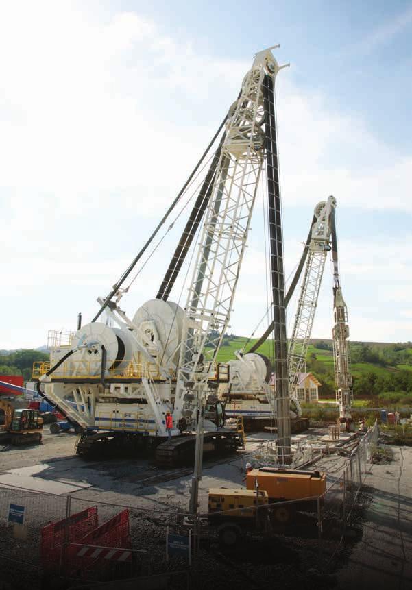
13 Soilmec Equipment More than 25 years experience of Trevi Group companies (enriched also by Rodio) in the use of hydromill technologies, have enabled Soilmec to engineer the most advanced fleet of hydromill equipment and to provide the global foundation market with a complete range of models and accessories. After years of development, Soilmec and Trevi have made a new step in the history of foundations, reaching the prestigious world record depth of 250 m UNDERCARRIAGE BASE MACHINE CAB MUD HOSE WINDER HYDRAULIC HOSE WINDER BOOM MAST TYPE HYDROMILL MODULE CUTTING MOTORS AND DRUMS


14 Soilmec Equipment Cougar The Hose Wheels Design (HWD) is positioned below the cathead so that it can easily follow the hydromill movements with a tensioning and rewinding automatic system. It arises from the need to move simultaneously the hydraulic and bentonite mud circulation hoses to the cutting unit. Model Diesel engine Weight class Height Cutting depth Suggested milling unit Cougar SC kw 100 t 34 m 52 m SH-30 Cougar SC kw 135 t 40 m 63/56 m SH-30 / SH-40
 hydromill")


 SH-30 / SH-40 (SH-50 **) Tiger SC-200 c/w P450 450 + 450* kw 200 t 30 m 250")
15 Soilmec Equipment Tiger With the aim of meeting the need for increased diaphragm wall depth in the most challenging soil conditions, Soilmec has designed the HDD (Hose Drums Design) hydromill configuration. Hydraulic and mud winders are positioned on a base carrier, allowing high depth drilling performances. Model Diesel engine Weight class Height Cutting depth Suggested milling unit * External power pack ** High depth version Tiger SC kw 135 t 23.7 m 100 m (150 m **) SH-30 / SH-40 (SH-50 **) Tiger SC-200 c/w P * kw 200 t 30 m 250 m SH-40 / SH-50 The hydromill is cable-suspended to the supporting crane s boom through a cathead and a motorized swivel, manufactured under Soletanche Fressynet license, located at the top of the hydromill frame.

16 Hydromill_001 03/2016 All technical data are purely indicative and subject to change without notice This brochure has been edited and distributed by SOILMEC Spa. The present document cancels and override any previous ones. This brochure shall not be distributed, reproduced or exhibited without SOILMEC Spa. authorization in accordance with to SOILMEC web site disclaimer condition. SOILMEC Spa distributes machinery and structures all over the world, supported by SOILMEC Spa subsidiary companies and dealers. The complete Soilmec network list is available on the web site