AASHTO LRFD Seismic Bridge Design. Jingsong Liu July 20, 2017
|
|
|
- Brook Garrett
- 5 years ago
- Views:
Transcription
1 AASHTO LRFD Seismic Bridge Design Jingsong Liu July 20, 2017
2 History of AASHTO Seismic Specifications 1981: ATC-6, Seismic Design Guidelines for Highway Bridges. 1983: Guide Specifications for Seismic Design of Highway Bridges, 1st Edition. 1991: the guidelines were formally adopted into the Standard Specifications for Highway Bridges, then revised and reformatted as Division I-A. 1994: Division I-A became the basis for the seismic provisions included in the AASHTO LRFD Bridge Design Specifications. The latest version is 7 th edition with 2016 Interim.
3 2009: Guide Specifications for LRFD Seismic Bridge Design, 1 st Edition. An alternate to the seismic provisions in the AASHTO LRFD Bridge Design Specifications 2011: Guide Specifications for LRFD Seismic Bridge Design, 2 nd Edition, with 2012, 2014, and 2015 Interim Revisions.
4 Seismic Hazard Map and Response Spectrum 2007 (4 th Edition LRFD) and earlier: The seismic hazard maps have 10% probability of exceedance in 50 years (which is approximately equivalent to a 15% probability of exceedance in 75 years). This corresponds to a return period of approximately 475 years. 1 (1 PP) 50 = 0.10; PP = pppppp yyyyyyyy 1/PP = yyyyyyyy
5 PGA Seismic Map Before 2008
6 2008 Interims and later: The seismic hazard maps are revised and have 7% probability of exceedance in 75 years. This corresponds to a return period of approximately 1000 years. 3-Point Method. o The peak ground acceleration coefficient (PGA) at 0.0 sec and o The short-period spectral acceleration coefficient (S S ) at 0.2 sec o The long-period spectral acceleration coefficients (S 1 ) at 1.0 sec The recurrence period from 475 to 1000 year does not double the demand.

7 PGA Seismic Map Since 2008
8 Site Effects: Table Site Class Definitions Sites shall be classified by their stiffness as determined by the shear wave velocity in the upper 100 ft.
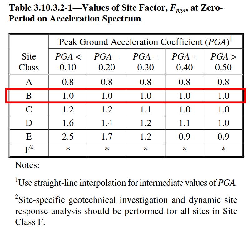
9 o Site Class B (soft rock) is taken to be the reference site category for the USGS and NEHRP MCE ground shaking maps. o Site class B rock is therefore the site condition for which the site factor is 1.0. o Site classes A, C, D, and E have separate sets of site factors for zero-period (F pga ), the short-period range (F a ) and longperiod range (F v ), as indicated in Tables , , and AA SS = FF pppppp PPPPPP SS DDDD = FF aa SS SS SS DD1 = FF vv SS 1
10
11
12
13 Seismic Performance Zones
 Pink Area: S D1 >0.15 based on Site Class D.")
14 NC 1.0 Sec spectral acceleration coefficients (S 1 ) Pink Area: S D1 >0.15 based on Site Class D.
15 NCDOT Structure Design Manual, FIGURE 2 1 SEISMIC ZONE, LRFD BRIDGE DESIGN SPECIFICATONS
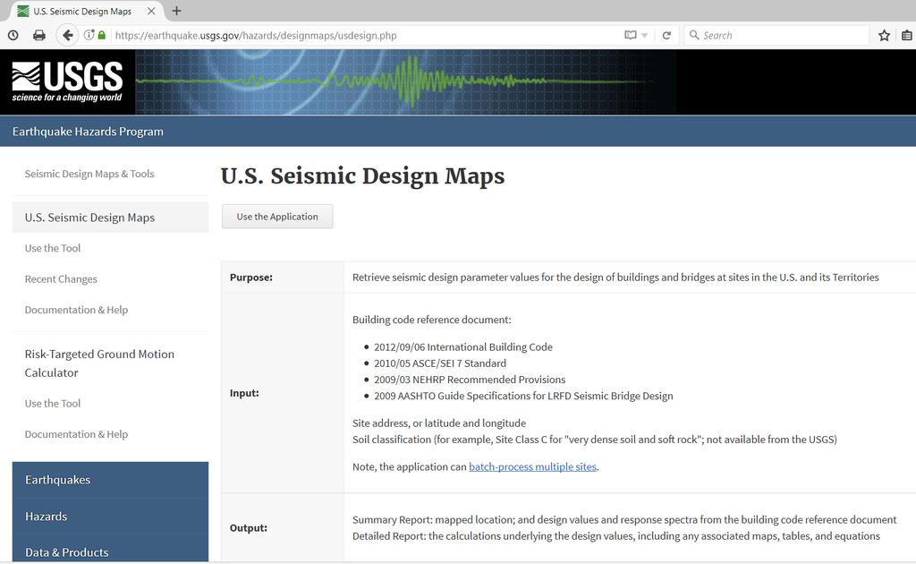
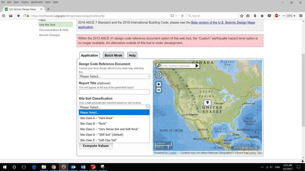
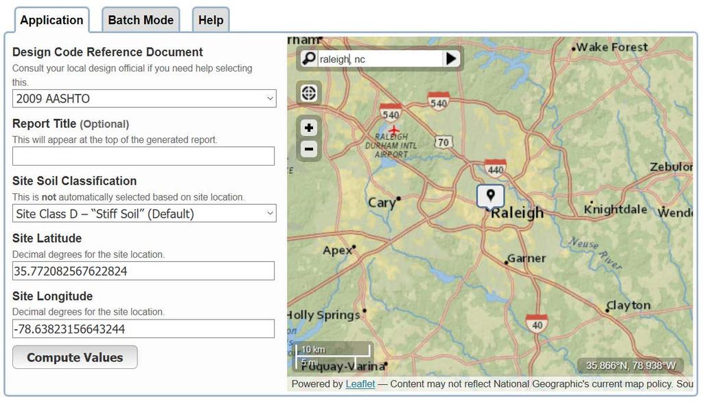
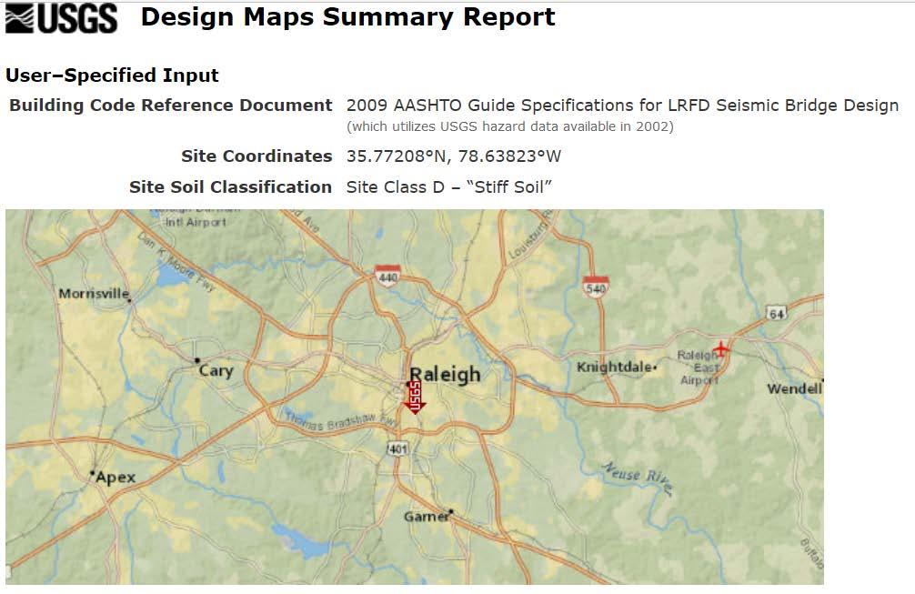
16 USGS website provides a tool to calculate the acceleration coefficients per AASHTO seismic hazard maps in US. Site Latitude and Longitude Street address City, State names Zipcode
17
18

19
20
21
22
23
24
25
26 For Seismic Performance Zones 2 and higher, Design Response Spectrum needs to be generated.
27 AASHTO LRFD Load Combinations
28 AASHTO Earthquake Load Case: Extreme Event I Use load factors of 1.0 for all permanent loads γ EQ is usually 0.0 For ordinary standard bridge, but it can be other values as high as 0.5 on a project specific basis for operationally important structures.
29 1. Simple span bridges: o Seismic analysis is not required for single-span bridges, regardless of seismic zone. o Connections between the bridge superstructure and the abutments shall be designed for the minimum force requirements as specified in Article o Minimum support length requirements shall be satisfied at each abutment as specified in Article The empirical support length shall be taken as: NN = ( L L )( SS 2 )
30
31
32 2. Seismic Zone 1 o A s <0.05, the horizontal design connection force in the restrained directions shall not be less than 0.15 times the vertical reaction due to the tributary permanent load and the tributary live loads assumed to exist during an earthquake. o For other A s, the horizontal design connection force in the restrained directions shall not be less than 0.25 times the vertical reaction due to the tributary permanent load and the tributary live loads assumed to exist during an earthquake Interim drops the requirement: The horizontal design connection force shall be addressed from the point of application through the substructure and into the foundation elements.
33
 for Multispan Bridges * = no seismic analysis required UL = uniform load elastic method SM = single-mode elastic")
34 3. Seismic Zones 2 and up Analysis for Earthquake Loads (LRFD 4.7.4) for Multispan Bridges * = no seismic analysis required UL = uniform load elastic method SM = single-mode elastic method MM = multimode elastic method TH = time history method
35 Effective Flexural Stiffness of Cracked Reinforced Concrete Sections
36 Generally two global dynamic analyses should be developed to approximate the nonlinear response of a bridge with expansion joints because it possesses different characteristics in tension and compression (AASHTO Guide Spec 5.1.2): o In the tension model, the superstructure joints are permitted to move independently of one another in the longitudinal direction. Appropriate elements connecting the joints may be used to model the effects of earthquake restrainers. o In the compression model, all of the restrainer elements are inactivated and the superstructure elements are locked longitudinally to capture structural response modes where the joints close up, mobilizing the abutments when applicable.
37
38 Actual/Ductile Response 1 Onset of cracking 2 Pseudo-yielding point 3 Maximum plastic deformations 4 Collapse
39 Maximum displacements of elastic systems and similar period ductile systems are roughly equal.
40 Idealized Elasto-Plastic Response
41 Ductility Factor µ
42 Strength and Ductility Relationship
43 Force Based Design Determination of Modified Design Force
44 Table Response Modification Factors Substructures Operational Category Substructure Critical Essential Other Wall-type piers larger dimension Reinforced concrete pile bents Vertical piles only With batter piles Single columns Steel or composite steel and concrete pile bents Vertical pile only With batter piles Multiple column bents If an inelastic time history method of analysis is used, the response modification factor, R, shall be taken as 1.0 for all substructure and connections.
45 Combination of Seismic Force Effects The elastic seismic force effects on each of the principal axes of a component resulting from analyses in the two perpendicular directions shall be combined to form two load cases as follows: o 100 percent of the absolute value of the force effects in one of the perpendicular directions combined with 30 percent of the absolute value of the force effects in the second perpendicular direction, and o 100 percent of the absolute value of the force effects in the second perpendicular direction combined with 30 percent of the absolute value of the force effects in the first perpendicular direction.
46 Capacity Protection Design: Reaching the elastic capacity (yield) of one member protects adjacent members from excessive force. Member Strengths Nominal strength, S n Design strength, S d = φ S n φ: strength reduction factor < 1.0 Overstrength, S o = φ o S n AASHTO LRFD APPENDIX B3 OVERSTRENGTH RESISTANCE φ o : overstrength factor > 1.0, 1.3 for reinforced concrete columns and 1.25 for structural steel columns
47
48 For reinforced concrete columns MM oo = 1.3MM nn VV oo = MM oo LL ii
49 1. Seismic Zone 2 Except for foundations, seismic design forces for all components, including pile bents and retaining walls, shall be determined by dividing the elastic seismic forces, obtained from Article , by the appropriate response modification factor, R, specified in Table Seismic design forces for foundations, other than pile bents and retaining walls, shall be determined by dividing elastic seismic forces, obtained from Article , by half of the response modification factor, R, from Table , for the substructure component to which it is attached. The value of R/2 shall not be taken as less than 1.0.
50 2. Seismic Zones 3 and 4 The design forces of each component shall be taken as the lesser of those determined using: Modified design forces shall be determined as specified in Article , except that for foundations the R-factor shall be taken as 1.0; or Inelastic Hinging Forces resulting from plastic hinging at the top and/or bottom of the column for all components of a column, column bent and its foundation and connections.
51 Overstrength Forces for Zones 2, 3 & 4
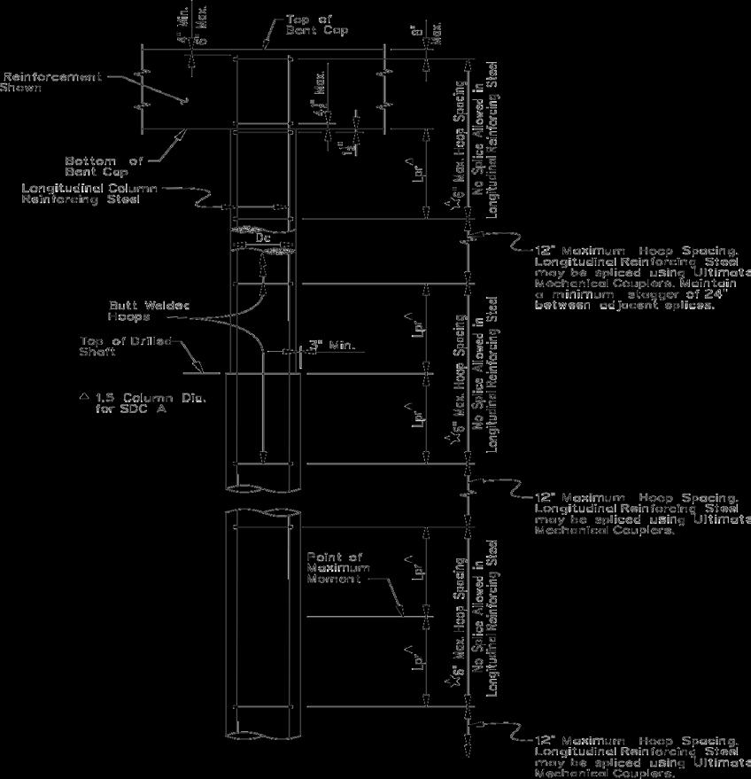
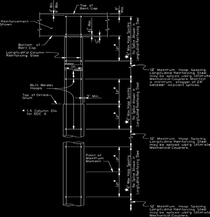
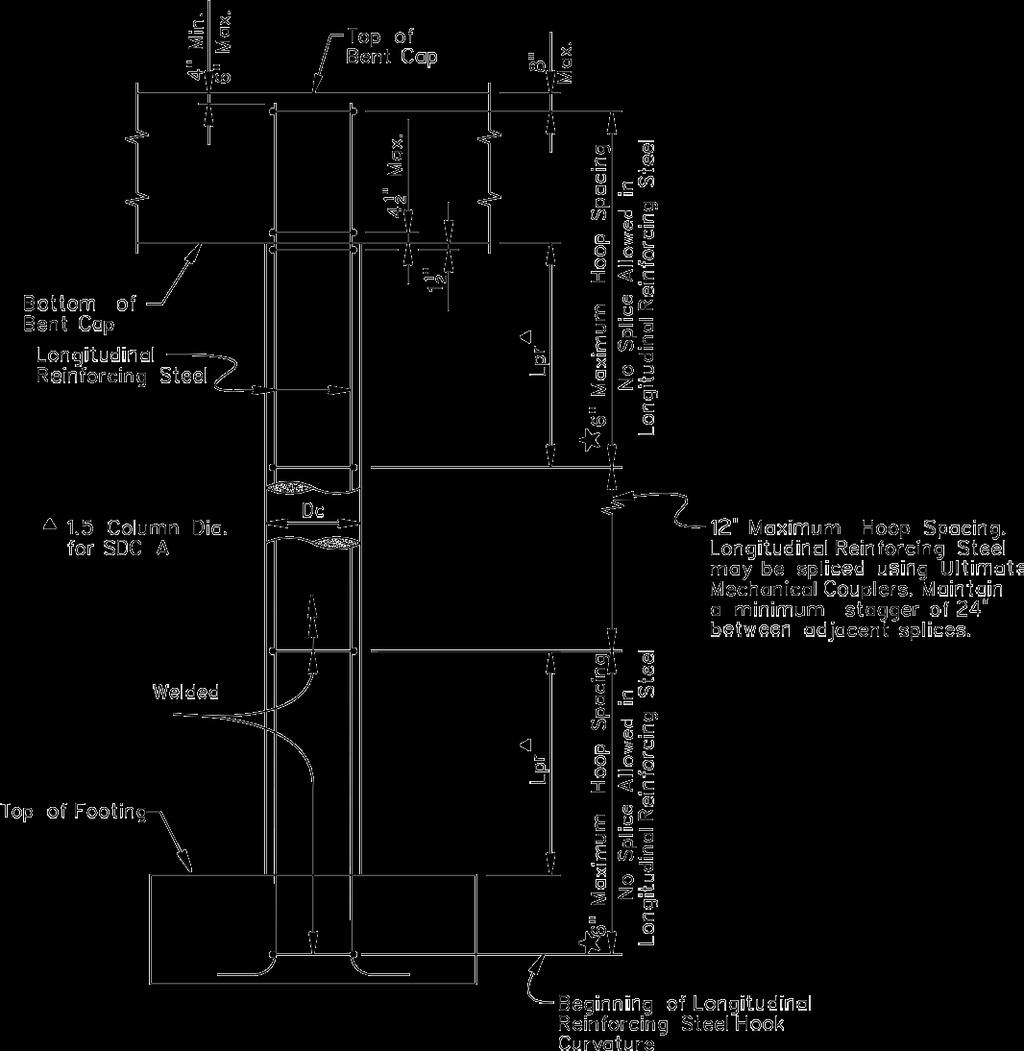
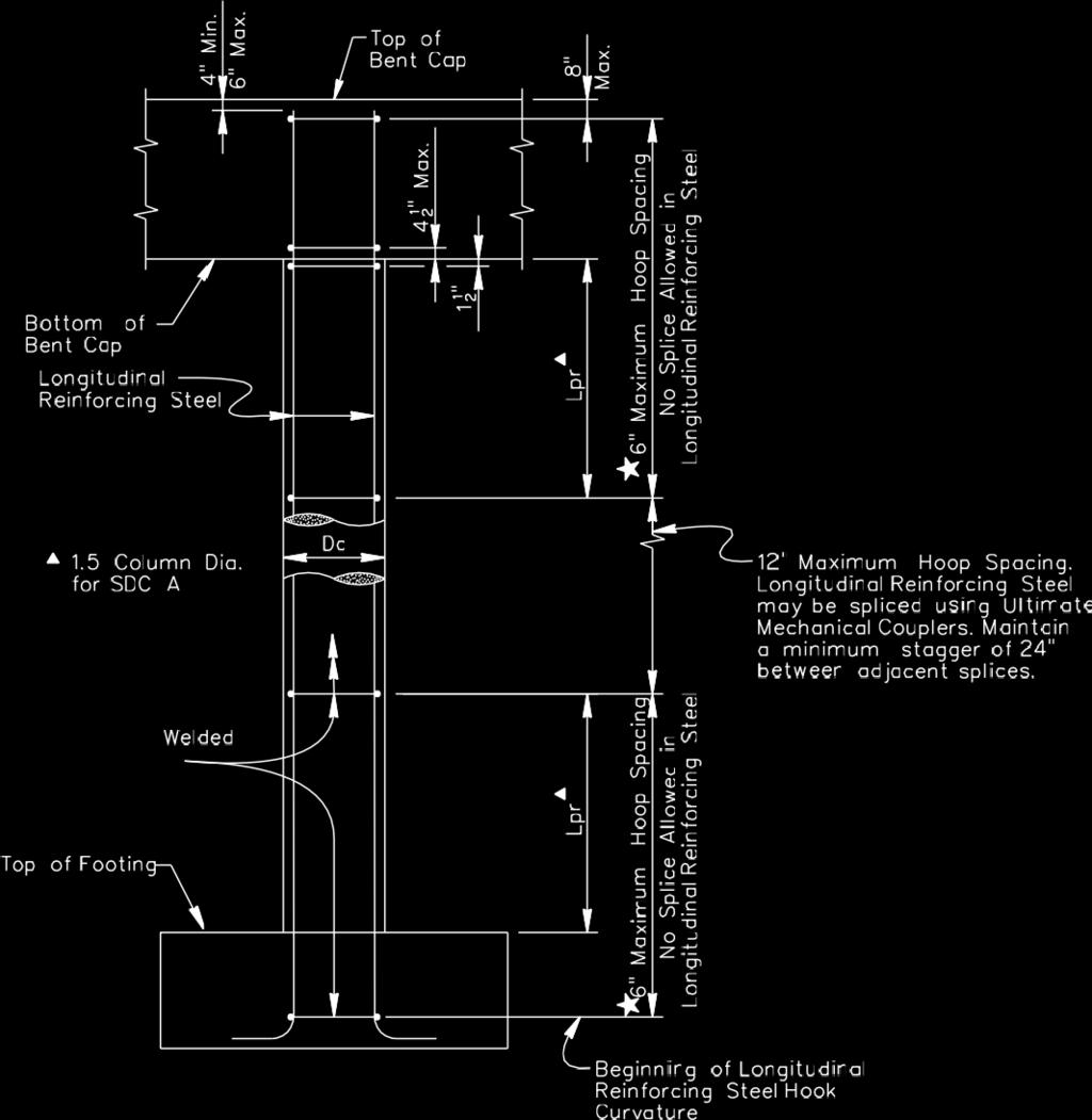
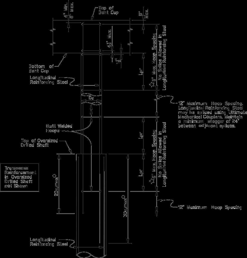
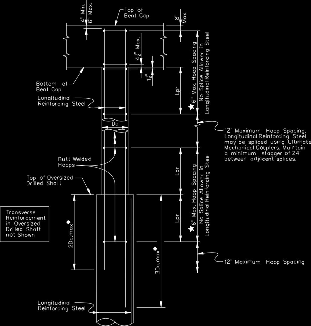
52 For SDCs B and C, ASTM A 706 Grade 60 reinforcing steel shall be used in members where plastic hinging is expected. ASTM A 615 Grade 60 reinforcing steel may be used in members where plastic hinging is expected, with the Owner s approval. For SDC D, ASTM A 706 Grade 60 reinforcing steel shall be used in members where plastic hinging is expected. Transverse reinforcement shall be butt-welded hoops. Spiral reinforcement is not allowed in cast-in-place concrete columns and drilled shafts. Where ductility is to be assured or where welding is required, steel conforming to the requirements of ASTM A706, Low Alloy Steel Deformed Bars for Concrete Reinforcement, should be specified.
53 A706 versus A615 low-alloy, welding steel tighter strength limits with yield strength not to exceed 18 ksi above minimum fy tensile strength must be at least 1.25 of the actual yield strength used where greater ductility is required generally available -- a small premium of compared to A615 bars
54
55 APPENDIX A3 SEISMIC DESIGN FLOWCHARTS Figure A3-1 Seismic Design Procedure Flow Chart
56 Figure A3-2 Seismic Detailing and Foundation Design Flow Chart
57 Displacement Based Method In forced based method, elastic demand force is applied with prescribed ductility factors R for anticipated Deformation. Ductile response is assumed to be adequate but without verification. In displacement based method, displacement demands are compared with displacement capacity. Ductile response is assured for each seismic design category.
58 Table Partitions for Seismic Design Categories A, B, C, and D
59 1. Design Requirements For Seismic Design Category A The same as AASHTO LRFD 2. Design Requirements For Seismic Design Category B SDC B structures are designed and detailed to achieve a displacement ductility, µ D, of around 2. Use formula to perform displacement capacity verification Capacity Design Required for column shear & footing
60 3. Design Requirements For Seismic Design Category C SDC C structures are designed and detailed to achieve a displacement ductility, µ D, of around 3. Use formula to perform displacement capacity verification Capacity Design Required for column shear & footing
61 4. Design Requirements For Seismic Design Category D SDC D structures are designed and detailed to achieve a displacement ductility, µ D, of at most 6. The Nonlinear Static Procedure (NSP), commonly referred to as pushover analysis, shall be used to perform displacement capacity verification Capacity Design Required for column shear & footing
62 Capacity Design Principles For steel members: MM pppp = λλ mmoo MM nn where: M n = nominal moment strength for which expected steel strengths for steel members are used λ mo = overstrength factor taken as 1.2 For concrete members: Guide Specs 8.5 MM pppp = λλ mmoo MM pp
63
64 where: M ne : the expected nominal moment capacity based on the expected concrete and reinforcing steelstrengths when either the concrete strain reaches amagnitude of or the reinforcing steel strain reaches the reduced ultimate tensile strain as defined in Table M p = idealized plastic moment capacity of reinforced concrete member based on expected material properties M po = overstrength plastic moment capacity λ mo = overstrength magnifier = 1.2 for ASTM A 706 reinforcement = 1.4 for ASTM A 615 Grade 60 reinforcement
65
66
67
68

69
70 QUESTIONS?