Friction Force of Fastener-Typed Frictional Damper Applied to Pre-cast Concrete Curtain Wall
|
|
|
- Jasper Chandler
- 5 years ago
- Views:
Transcription

1 Friction Force of Fastener-Typed Frictional Damper Applied to Pre-cast Curtain Wall Tomokazu YOSHIOKA Kyushu University, Japan SUMMARY: The author proposed the earthquake vibration control wall that used its connection between precast reinforced concrete curtain wall and steel frame as friction damper. Friction force of proposed friction damper occurs at two slipping surfaces between reinforced concrete wall panel and steel angle attached to building frame and a portion of friction force is transmitted by tightened bolt. In this paper, we conducted dynamic slipping test of model specimens in order to investigate the friction force of proposed friction damper that tightened by different initial bolt tensions. As test results, approximately same slip coefficients (equal to about 0.8) were obtained from specimens that were tightened by different initial bolt tensions while these ones used conical spring washers inserted between the nut of tightened bolt and the plain washer. Keywords: Earthquake Vibration Control, Precast Reinforced Curtain Wall, Friction Damper 1. INTRODUCTION Precast reinforced concrete curtain wall is used as one of envelopes for steel buildings and is designed as a non-bearing wall in Japan. The author is developing new earthquake vibration control curtain wall system that uses and stiffness of such a non-bearing curtain wall without its damage while a great earthquake. The author proposed that the connection between precast reinforced concrete curtain wall and steel structure frame was used as friction damper. Fig.1 shows the connection of proposed vibration control curtain wall system (Yoshioka 2008, p.1117). CURTAIN WALL PRECAST REINFORCED CONVENTIONAL BOLT JOINT COLUMN COLUMN PRECAST REINFORCED SLIDING CUBOID TIGHTENED BOLT FRICTION DAMPER ANGLE FRAME DEFLECTS HORIZONTALLY ANGLE SECTION SLIDING CUBOID FRICTIONAL SLIPPING Figure 1. Concept of the earthquake vibration control curtain wall system TIGHTENED BOLT INNER SIDE
2 SLIDING CUBOID BOLT PLATE OF ANGLE FORCE TRANSMITTED BY BENDING SHEAR OF BOLT DAMPING FORCE FRICTION FORCE FRICTION FORCE FRICITON FORCE BETWEEN AND ANGLE FRICITON FORCE BETWEEN ANGLE AND SLIDING CUBOID Figure 2. Proposed friction damper As shown in Fig.2, this connection has two frictional surfaces. One of them is the boundary between curtain wall panel and steel angle. Another is the boundary between steel angle and concrete sliding cuboid. The friction force occurred on the latter boundary is transmitted by the bending shear resisting of the tightened bolt. In this system, it is easy to install a lot of dampers to the connection between outer walls and structural frame and the damper doesn t need large friction force capacity relatively. YOSHIOKA et al investigated that in order to keep the story drift angle of steel rigid frame to less than 0.01 radians during a great earthquake, the friction force of this damper is need to keep more than 20kN until total slip displacement reached to 1000mm (Yasui 2010,p.29). YOSHIOKA et al tested some model specimens of proposed friction damper (Yoshioka 2008, p.1117). When 25kN initial tension was given into the bolt of the specimen, more than 20kN friction force was obtained. However the different initial bolt tensions given into the bolt were not discussed. In this paper, the dynamic slipping tests focused on the frictional damping connection were conducted to get the fundamental information regarding the frictional-slipping characteristics between the steel plate and concrete surface tightened by different initial bolt tensions. 2. SPECIMENS The detail of the friction damper model specimen is shown in Fig.3. As shown in Fig.4, the specimen was set into the steel frame for testing. The specimen corresponds to a part of the connection shown in Fig.1. The concrete wall panel and the steel plate were tightened together through a 24mm diameter steel bolt anchored in the concrete wall panel. The steel plate was imitated to the steel angle which connected a curtain wall with a structural frame. The concrete sliding cuboid was inserted into the boundary between the steel plate and the steel plain washer to prevent from seizure on dry friction of same metals. 24mm dia. bolt Steel plain washer sliding cuboid sliding cuboid Inserted conical spring washer x1 x mm dia. bolt wall panel Guide angle wall panel Load cell Steel plain washer 250 Guide angle SIDE VIEW SECTION Figure 3. Detail of the friction damper model specimen The size of concrete wall panel is 250mm in width, 1220mm in length and 250mm in thickness. In order to apply both side of the panel to the slipping test, the bolt was projected on both sides. The friction surfaces of the concrete wall panel were provided with the condition after removing plywood.
3 The light-weight concrete was applied to the concrete wall panel as well as existing precast reinforced concrete curtain wall. The steel plate is a mild steel of the Grade 400MPa tensile. The mill scale covered on the surface of the steel plate wasn t eliminated in the tests. To make the slipping displacement possible, the 30mm wide and 260mm long slot was provided in the steel plate. The two sizes of the concrete sliding cubic were planed dependent on the given initial bolt tension as shown in Fig.5. There was a 26 mm diameter bolt hole at the centre of the concrete sliding cuboid. In order to keep the contact area around the bolt hole, the thickness of the concrete sliding cuboid was decreased by 2mm from edge to 80mm or 95mm length. The friction surface of the cuboid was the same as the concrete wall panel. The concrete sliding cuboid was created by a high early concrete for shortening construction time. A guide steel angle (L-50mm x 50mm x 6mm) was attached on the steel plate to prevent the concrete sliding cuboid from rotating while the steel plate was sliding. The mechanical properties of concrete and steel used in the specimens were shown in Table 1. A 400 wall panel sliding cuboid column wall panel sliding cuboid 24mm dia bolt ,250 A' A-A' SECTION Figure 4. Model specimen set into the loading steel frame Friction surfase 2mm dicrease mm dia. bolt hole 170 Friction surfase 2mm dicrease 26mm dia. bolt hole (a)n250,n375 Figure 5. sliding cuboid Table 1. Mechanical properties of concrete and steel of the specimens Specimen Yield Tensile Young's modulus unit weight Compressive (b)n500 of wall panel of sliding cuboid Young's modulus Unit weight Compressive Young's modulus (MPa) (MPa) (GPa) (kn/m 3 ) (MPa) (GPa) (kn/m 3 ) (MPa) (GPa) N250,N N
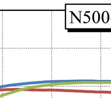
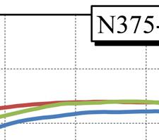
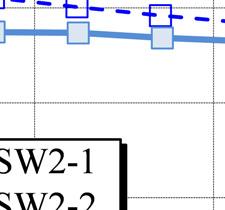
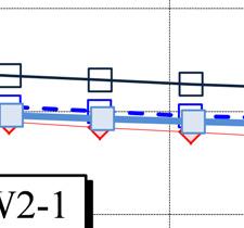
4 In the experiments, six test series were planned to compare the difference of the initial tension given into the bolt (25kN, 37.5kN and 50kN) and the existence of the conical spring washer which was inserted between the nut and the plain washer. The bolt tension of 50kN is equal to about two thirds of yield tensile capacity of a 24 diameter steel bolt. Conical spring washers were expected to keep the bolt tension while the steel plate was sliding. The Conical spring washer categorized in JIS(Japanese Industrial Standards) B1251 was used. Table 2 summarizes the entire scheme. Table 2. Summary of testing condition Series Number of specimen Bolt tension (kn) Number of conical spring washer N250-SW N250-SW1 3 1 N375-SW N375-SW1 3 1 N500-SW N500-SW2 3 2 The load that enforced slipping at the connection surfaces was applied to the upper steel beam by a 200kN servo actuator while the concrete wall panel were fixed to the steel frame as shown in Fig.4. The time history of the enforced lateral displacement was the sinusoidal wave as shown in Fig.6. The friction force, the relative slipping displacement between the concrete sliding cuboid and the steel plate and the bolt tension were measured. The intervals of the data sampling were set to 3 milliseconds, which was the maximum speed of the measuring equipment. Displacement(mm) time(sec) Figure 6. Time history of the enforced lateral displacement 3. TEST RESULT Fig.7 shows the relations between the friction force and the slip displacement obtained by the experiments of exemplary six specimens which included N250-SW0-1, N250-SW1-1, N375-SW0-1, N375-SW1-1, N500-SW0-1 and N500-SW2-1. Fig.8 shows the relations between the friction force and the total slip displacement of the same specimens. Here, the total slip displacement is the summation of slipping displacement experienced by the time from the beginning of the test. As shown in Fig.7, all specimens showed approximately rigid perfectly plastic friction force and displacement relations. The friction force obtained from all specimens rose approximately according to the increase in the tensions given into the bolt initially. As shown in Fig.8, the friction force obtained from the specimens with inserted conical spring washer continued to approximately level off during slipping except N500 test series. On the other hand, the friction force obtained from the specimens without conical spring washer and the specimens of N500 test series tended to be
5 decreasing gradually as the total slipping displacement increases. (a) Specimens without conical spring washer ( b) Specimenss with conical spring washers Figure 7. Friction force and slip displacement relations r u (a) Specimens without conical spring washer ( b) Specimenss with conical spring washers Figure 8. Friction forcee and total slip displacement relations Fig.9 shows the relation between the bolt tension ratio and total slip s displacement. Here,, the bolt tension ratio is that the tension measured while slipping was dividedd by the initial tension given into the bolt. The bolt tension ratioss plotted in Fig.9 are the averages of the maximum and minimum


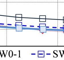


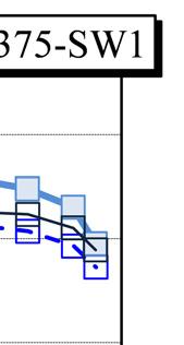
6 Figure 9. Bolt tension ratio and total slip displacement relations s (a)scope from the beginning to 6mm displacement (b) Scope covered the entire range displacement Figure 10. Slip coefficient and total slip displacement relations
7 values obtained at each slipping cycle. In the all specimens, the bolt tension ratio was decreasing as the total slipping displacement increases because the friction surfaces of the concrete wall panel and the concrete sliding cuboid wore out. Inserting of conical spring washer prevented the decrease of bolt tension partly expect N500 test series. Fig.10 shows the relations between the slip coefficient and the total slip displacement obtain from only specimens which used conical spring washer. Here, the slip coefficient is that the load applied to the steel plate was divided by the tension force, which was introduced into the steel bolt before loading, not considering the number of friction surfaces. Here, the values of friction coefficient plotted in Fig 10(b) are the average values obtained at each slipping cycle. Approximately same slip coefficients (equal to about 0.8) were obtained from specimens that were tightened by different initial bolt tensions. However, the slip coefficient obtained from the specimens of N500 test series was merely smaller compared to the other two test series because of a little large decreasing of the bolt tension. More than 0.8 slip coefficient seemed to occur when the slip displacement reached to about 3mm. 4. CONCLUSION We conducted dynamic slipping test of model specimens in order to investigate the friction force of proposed friction damper that tightened by different initial bolt tensions. As test results, approximately same slip coefficients (equal to about 0.8) were obtained from specimens that were tightened by different initial bolt tensions while these ones used conical spring washers inserted between the nut of tightened bolt and the plain washer. REFERENCES Yoshioka, T., Chujo, T. and Noguchi, K. (2008). Slipping performance of steel-concrete frictional sliding joint. Proceedings of the Japan Institute,Vol.30:No.3, Yasui, N., Yoshioka, T., Kutani, K., Sirakawa, T. and Kawano, A. (2010). A Study on energy dissipation fasteners for PCa curtain wall. Steel Constrauction Engineering,Vol.17:No.68,29-44