Project 184. Alder Creek Diversion Fish Screen Conceptual Plan
|
|
|
- Ezra Hopkins
- 5 years ago
- Views:
Transcription
1 TECHNICAL MEMORANDUM Project 184 Alder Creek Diversion Fish Screen Conceptual Plan El Dorado Irrigation District 2890 Mosquito Road Placerville, CA Prepared By: Robert Aramayo, GANDA Darryl Hayes, ISI J July 18, 2007 Version 4.0 1
2 Introduction El Dorado Irrigation District (EID) contracted and Intake Screens, Inc. (ISI) to investigate design concepts for a screened diversion at the Alder Creek Dam and to prepare a conceptual design for approval. The proposed intake screen will replace an existing bar grate structure at the site with a state-of-the-art fish screen that will meet California Department of Fish and Game (DFG) fish screen criteria for trout fry. The proposed screen system will also meet Federal Energy Regulatory Commission (FERC) license conditions, enabling EID to continue its hydropower operations. The new screen will connect directly to the intake pipeline and operate within the same general conditions as the existing intake. The existing diversion is located at a small dam on Alder Creek. The dam s broad-crested weir creates a minimum water depth of about 2 feet at the diversion. Below the intake structure is a low level outlet to lower the water level to below the spillway elevation when necessary. A manually operated slide gate on the existing diversion controls the flow into the 18-inch pipeline. The maximum diversion capacity is approximately 15 cfs. There is presently no electrical power to the site. The closest power source is approximately 4000 feet from the site. Section 9 of the Project 184 Settlement Agreement, U.S. Forest Service 4(e) condition 39, and California Water Resources Control Board Clean Water Act water quality certification condition 12 require preparation of a plan for screening both Alder and Carpenter Creeks for all lifestages of trout. On May 11, 2007 EID submitted a letter to FERC stating its intent to discontinue use of the Carpenter Creek Diversion and therefore eliminate construction of a fish screen at that diversion. On June 6, 2007 FERC responded to the EID letter with direction to file a license amendment application for removal of the Carpenter Creek Diversion from Project 184 after completing the necessary agency consultation. Fish Screen Criteria and Concepts Considered A fish screen must be constructed to accommodate a diversion rate between 5 and 15 cfs while meeting the design guidelines established by the DFG (see Appendix A). The screen will protect trout fry and other fish species from entrainment and impingement at the diversion. The proposed fish screen should be designed and sited to minimize the intake footprint and to minimize debris collection, damage potential, and sedimentation issues. A screen area of at least 45 square feet is required to meet the criteria. Since debris clogging and screen maintenance can be one of the most critical factors in selecting a screen design, only proven systems that have operated in similar environments were considered. Additional screen protection features could be added to any installation and should be considered due to the potential for heavy debris loads and rocks to damage the screen. The implementation of these measures however, should consider the possible unintended consequences of bed load deposition and additional maintenance activities at the site. 2
3 Table 1 summarizes the design criteria used in the evaluation of the various screen types being considered for this project. Table 1. Fish Screen Design Criteria for Evaluation Design Criteria Opening Size: 1.75 mm for slotted profile bar screens or 2.38 mm (measured diagonally) for woven wire mesh or perforated plate openings. (Note: Wedgewire screens are preferred.) Maximum Screen Approach Velocity: 0.33 feet per second uniformly distributed across the screen surface. (Note: To meet these criteria, a minimum wetted screen area of 45 square feet is necessary.) Minimum Open Area: 27 percent (Note: 50 percent open area is preferred to reduce slot velocity.) Screen Material: stainless steel, type 304. Automated Cleaning System: capable of being continuously cleaned as necessary. Given the site constraints and DFG fish screen criteria, there are only a few available options which include: - Sloping flat-plate wedgewire screens with rake or brush cleaning systems - Cylindrical wedgewire screens with brush cleaning system - Cone-shaped wedgewire screen with brush cleaning system Table 2 describes some of these basic concepts considered and their advantages and disadvantages. Table 2. Advantages and Disadvantages of Various Fish Screen Alternatives Type Description Advantages Disadvantages Sloping Flat Plate Screen Panels with Horizontal or Vertical Rake/Brush system (Custom Manufactured Screen) Flat panel wedgewire screens about 16 feet long and sloped at a 45 degree angle in roughly 2 feet of water. Top of screen would be above high water, as would raking/brush system. Simple concept; customizable system Large footprint; requires larger structure to keep system above high water; long structure more susceptible to damage; visual impacts; additional design work; difficult construction. Vertically oriented rotating cylindrical screens with brush cleaner. (Made by Intake Screens, Inc.) Cone shaped screen (Made by Intake Screens, Inc.) Two, 48-inch x 24-inch drum screens oriented vertically and connected to manifold. A protective cage could be built over the screens. Screens would have internal and external brush system. One, 8-foot diameter by 2-foot high cone-shaped wedgewire screen mounted on concrete base. Screen cleaning by brush system with underwater hydraulic motor. Durable and proven to operate in high debris and high flow events; simple design; minimal visual impacts; screen units somewhat lighter than cone. Screen has most wetted area in low water situations in single unit; Screen can be directly hooked to existing intake using existing gate; Requires multiple screen units due to shallow depth and complicating system. Screen removal requires specialized equipment or additional effort to remove or install unit if necessary. 3
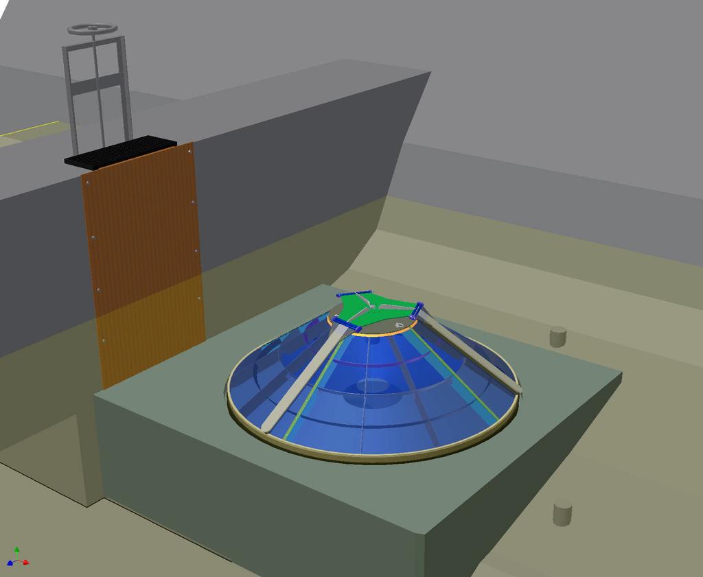
4 A protective cage could be built around unit. strong design; excellent cleaning ability; low energy requirements; minimal visual impacts. Preferred Fish Screen Description - Cone Screen A Cone Screen design was the preferred design concept for development after discussion with the EID staff. This decision was based in part on several factors including: ability to operate in shallow or deep conditions; excellent track record for performance; durability; minimal visual impacts; ease of installation; minimal power requirements; and operational flexibility. The design of this screen system includes the following key elements: 1. Fish screen unit 2. Concrete fish screen base with formed intake channel 3. Adapter plate on existing intake 4. Debris Protection 5. Fish Screen Control Panel 6. Solar Power System 7. Cathodic Protection System Each of the elements on the preferred system is described in more detail below. Several design plans prepared to approximately the 30 percent level (conceptual design) are presented in Appendix B. Renderings of the proposed project are also included to illustrate the design features and components of the proposed system. Fish Screen Unit An ISI brush cleaned cone screen will be used to screen the existing diversion. This unit has a maximum capacity of 18 cfs at an approach velocity of.33 fps and is designed to meet the fish screen criteria (maximum diversion rate will be 15 cfs in compliance with water right). A type 304 stainless steel wedgewire screen covers 54.8 square feet of the cone surface. The continuous slot screen will have inch width wires (#69SV wire) and a slot opening of inch (50 percent net open area). The screen s frame will also be fabricated of type 304 stainless steel. The interior of the cone structure shall be braced to insure roundness and concentricity to within 1/8-inch. The frame with wedgewire covering shall be designed to support a dead load equivalent to 8 feet of water. Flow uniformity through the screen surface is managed using an internal cone baffle system to prevent high velocity areas. This system has been field tested at similar sites and with acceptable velocity uniformity. Oversizing the screen unit will also minimize approach velocity hot spots on the screen and allow for some non-uniform intake flows across the screen unit. Two double-hinged brush arms will be attached to a centrally located rotating hub. These rearward angled brush arms rotate at a rate of approximately 4 rpm over the screen surface 4
5 and brush off any material that may have collected on the wedgewire. Nylon brush strips will be attached to the under side of the brush arms by using a series of height adjustable brush clamps that are spaced on 5-inch centers. The brush material shall be 6-12 nylon,.043- inch in diameter in a # 7 stainless steel channel. The overall trim of the brush shall be 2 and 3/8-inches. All brush arm assembly components will be made of uncoated stainless steel or plastic. This assembly will be cathodically protected. A high torque marine duty hydraulic motor using ISO 32 hydraulic oil (accepted by the U.S. Fish & Wildlife Service, NOAA Fisheries, and the U.S. Environmental Protection Agency) is used to rotate the sweeping brush arms around the screen unit. A typical cleaning cycle is 60 seconds forward (counter-clockwise) and 60 seconds in reverse (clockwise). Cleaning cycle frequency can be set from continuous to once daily. Actual frequency will be adjusted according to the amount and type of debris present and so that the screen will not exceed the maximum velocity criteria by DFG. The energy used to power the cleaning system is minimal. A conservatively designed solar charged battery supply will be designed for this system as outlined below. Concrete Fish Screen Base with Formed Intake Channel The new screen requires a concrete base with an intake formed into the concrete. The intake beneath the screen will transition to the existing intake area on the dam face. The new base will slightly elevate the bottom of the cone screen base to ensure that most bed load materials will settle near the adjacent, and lower, existing low level outlet (sluice gate) rather on the screen material. This placement will allow the sluice to continue to prevent sediment accumulation on or near the screen. The existing intake grate and its concrete foundation must be removed prior to placement of the concrete base. A survey of the ponded area immediately in front of the existing intake indicates that the rock foundation under the concrete area is of sufficient depth and quality for placement of the base without additional excavation or reinforcement. To prepare this area for the concrete, the area must first be dewatered. Following dewatering, rebar dowels should be drilled into the base rock to ensure a secure bonding of the lightly reinforced concrete. Forms for the concrete can also be secured to the rebar to ease placement. The low level outlet should be sufficient to lower the water surface elevation during dewatering to a level that allows for a safe and functional work area. However, additional sump pumps may be required to further lower the water level. A small-height sandbag and plastic cofferdam around the area should be installed to keep flowing or standing water out of the area during construction and to prevent construction materials (e.g., concrete) from entering the stream. Adapter Plate on Existing Intake Once the existing intake grate and concrete base are removed, a steel plate over the existing dam face opening will need to be fit on the vertical face and bolted in place. The formed channel in the concrete base will pass through (or under) this plate. This plate will force all diverted flows to pass through the fish screen and enable the existing sluice gate to regulate diversion flows in the same manner as it did in the past. 5
6 Debris Protection The fish screen will be protected from heavy debris loads in Alder Creek through installation of a concrete stem wall and/or steel beams or plates, which will allow the debris to continue over the spillway as it currently does during high flows events. A debris protection cage may also be designed protect the fish screen from possible flood damage. This cage would be framed with its supports into the proposed concrete base outlined above. Details of this feature will be incorportated into the final design plans. The debris protection mechanism will not interfere with the fish screen function. It will be fabricated so that the screen can still be accessed if necessary. The ultimate design of the debris protection structure will be completed during the final design and will be dependant upon space availability around the screen. Fish Screen Control Panel The Fish Screen Control Panel (FSCP) houses the electrical and hydraulic components necessary to operate and monitor the fish screen system. This panel will be housed in a protected, lockable freestanding cabinet on or near the dam crest. It will include a programmable logic computer with human machine interface (HMI) to control the cleaning cycle and duration, as well as monitor the function of the fish screen hydraulic and electrical systems. Manual override switches will also be provided. A cellular-based telemetry system will be included to monitor and automatically report any problems with the system including blockage due to debris. The electrical and hydraulic components will be connected to a 110 or 240 VAC supply. A solar panel and battery system, described below, will supply the needed power. Solar Power System The intake is located in a remote area about 4000 feet from available power and at least 700 feet from a sunny open area. A solar array is proposed to supply the needed power from a site about 700 feet below the dam along the pipeline alignment in a southwest-facing open area. The proposed solar array will consist of four, 85-watt panels (340 watts) attached to two anchored poles. A weatherproof enclosure will house eight deep cycle batteries, a solar control panel for the charging system, and a power inverter. The proposed system will convert the battery powered 24 VAC system to a 110 VAC system so a higher voltage wire can run in a conduit back to the FSCP. This conduit will run along the pipeline alignment. The proposed system can be expanded with additional solar panels or batteries if necessary. Cathodic Protection System All major components subject to corrosion including the screen, hydraulic motor and its components, and brush cleaning assembly shall be electrically isolated and shall be cathodically protected according to their current generating potentials. Non-stainless steel structural parts will be blasted, primed, and coated with an epoxy coating. Sacrificial magnesium anodes will be placed on underwater parts as appropriate. 6
7 Regulatory Considerations The DFG Fisheries Engineering Program will be involved regularly throughout the design process. Following approval of this 30 percent design by all negulatory agencies identified in the FERC license, EID will prepare and provide for approval plans and design calculations for the fish screen as specified by Section 5.C. of the DFG Fish Screen Criteria outlined in Appendix A. EID will construct the fish screen to the satisfaction of DFG consistent with Section 5931 of the California Fish and Game Code. Following construction EID will provide access to the facility during operation for DFG to inspect and verify compliance with Fish Screen Criteria. In addition to the design and construction concerns, this project will also trigger a suite of regulatory requirements. Foremost of these is complying with the California Environmental Quality Act (CEQA). EID will take the lead on preparing an Initial Study to satisfy CEQA. In addition to CEQA, EID will also need to prepare a DFG Streambed Alteration Agreement. To comply with the Clean Water Act, EID will need a 404 permit from the U.S. Army Corps of Engineers and a 401 Water Quality Certification from the State Water Resources Control Board. The 404 permit likely can be satisfied with a Nationwide Permit. Installation Plan Construction activities to install the fish screen system should be conducted in summer when flows are low, access is easiest, and temperatures are warmer for concrete curing. Major construction activities include the following: - Transport heavy materials to (and from) the dam site via helicopter from a convenient staging area. o Materials would include fish screen, FSCP, solar system, generator, concrete (dry mix), concrete mixer, jackhammer, reinforcing materials, etc. - Drain reservoir via low level outlet. - Install temporary cofferdam around work site. o Install sump pumps if necessary. - Demolish intake (from dam face upstream only). - Install intake adapter to dam. o Grout-pack plate on dam face for intake adapter seal. - Drill into rock for rebar anchors. - Form concrete channel for intake. - Place reinforcing steel for concrete. - Mix and pour concrete. o Form in recessed area for fish screen. o Provide inserts or attachment points for screen protection cage. - Install anchors and small concrete pad for two pole mount solar panel array and battery box/panel. - Install solar power system. - Install conduit and wire along pipeline alignment between solar site and dam. 7
8 - Install fish screen with portable cherry picker. - Install fish screen control panel. - Fabricate and install protective screen cage. - Remove cofferdam and refill reservoir. - Test fish screen and control system. 8
9 Appendix A Attachment 1: STATE OF CALIFORNIA RESOURCES AGENCY DEPARTMENT OF FISH AND GAME FISH SCREENING CRITERIA June 19, STRUCTURE PLACEMENT A. Streams And Rivers (flowing water): The screen face shall be parallel to the flow and adjacent bankline (water s edge), with the screen face at or streamward of a line defined by the annual low-flow water s edge. The upstream and downstream transitions to the screen structure shall be designed and constructed to match the bankline, minimizing eddies upstream of, in front of, and downstream of, the screen. Where feasible, this on-stream fish screen structure placement is preferred by the California Department of Fish and Game. B. In Canals (flowing water): The screen structure shall be located as close to the river source as practical, in an effort to minimize the approach channel length and the fish return bypass length. This in canal fish screen location shall only be used where an on-stream screen design is not feasible. This situation is most common at existing diversion dams with headgate structures. The current National Marine Fisheries Service - Southwest Region criteria for these types of installations shall be used (Attachment A). C. Small Pumped Diversions: Small pumped diversions (less than 40 cubic-feet per second) which are screened using manufactured, self-contained screens shall conform to the National Marine Fisheries Service - Southwest Region criteria (Attachment A). D. Non-Flowing Waters (tidal areas, lakes and reservoirs): The preferred location for the diversion intake structure shall be offshore, in deep water, to minimize fish contact with the diversion. Other configurations will be considered as exceptions to the screening criteria as described in Section 5.F. below. A-1
10 2. APPROACH VELOCITY (Local velocity component perpendicular to the screen face A. Flow Uniformity: The design of the screen shall distribute the approach velocity uniformly across the face of the screen. Provisions shall be made in the design of the screen to allow for adjustment of flow patterns. The intent is to ensure uniform flow distribution through the entire face of the screen as it is constructed and operated. B. B. Self-Cleaning Screens: The design approach velocity shall not exceed: 1. Streams and Rivers (flowing waters) - Either: a feet per second, where exposure to the fish screen shall not exceed fifteen minutes, or b feet per second, for small (less than 40 cubic-feet per second) pumped diversions using manufactured, self-contained screens. 2. In Canals (flowing waters) feet per second, with a bypass entrance located every one-minute of travel time along the screen face. 3. Non-Flowing Waters (tidal areas, lakes and reservoirs) - The specific screen approach velocity shall be determined for each installation, based on the species and life stage of fish being protected. Velocities which exceed those described above will require a variance to these criteria (see Section 5.F. below). C. (Note: At this time, the U.S. Fish and Wildlife Service has selected a 0.2 feet per second approach velocity for use in waters where the Delta smelt is found. Thus, fish screens in the Sacramento-San Joaquin Estuary should use this criterion for design purposes.) D. C. Screens Which Are Not Self-Cleaning: The screens shall be designed with an approach velocity one-fourth that outlined in Section B. above. The screen shall be cleaned before the approach velocity exceeds the criteria described in Section B. E. Frequency Of Cleaning: Fish screens shall be cleaned as frequently as necessary to prevent flow impedance and violation of the approach velocity criteria. A cleaning cycle once every 5 minutes is deemed to meet this standard. F. Screen Area Calculation: The required wetted screen area (square feet), excluding the area affected by structural components, is calculated by dividing the maximum diverted flow (cubic-feet per second) by the allowable approach velocity (feet per second). Example: 1.0 cubic-feet per second / 0.33 feet per second = 3.0 square feet Unless otherwise specifically agreed to, this calculation shall be done at the minimum stream stage. A-2
11 3. SWEEPING VELOCITY (Velocity component parallel to screen face) A. In Streams And Rivers: The sweeping velocity should be at least two times the allowable approach velocity. B. In Canals: The sweeping velocity shall exceed the allowable approach velocity. Experience has shown that sweeping velocities of 2.0 feet per second (or greater) are preferable. C. Design Considerations: Screen faces shall be designed flush with any adjacent screen bay piers or walls, to allow an unimpeded flow of water parallel to the screen face. 4. SCREEN OPENINGS A. Porosity: The screen surface shall have a minimum open area of 27 percent. We recommend the maximum possible open area consistent with the availability of appropriate material, and structural design considerations. The use of open areas less than 40 percent shall include consideration of increasing the screen surface area, to reduce slot velocities, assisting in both fish protection and screen cleaning. B. Round Openings: Round openings in the screening shall not exceed 3.96mm (5/32in). In waters where steelhead rainbow trout fry are present, this dimension shall not exceed 2.38mm (3/32in). C. Square Openings: Square openings in screening shall not exceed 3.96mm (5/32in) measured diagonally. In waters where steelhead rainbow trout fry are present, this dimension shall not exceed 2.38mm (3/32in) measured diagonally. D. Slotted Openings: Slotted openings shall not exceed 2.38mm (3/32in) in width. In waters where steelhead rainbow trout fry are present, this dimension shall not exceed 1.75mm (0.0689in). 5. SCREEN CONSTRUCTION A. Material Selection: Screens may be constructed of any rigid material, perforated, woven, or slotted that provides water passage while physically excluding fish. The largest possible screen open area which is consistent with other project requirements should be used. Reducing the screen slot velocity is desirable both to protect fish and to ease cleaning requirements. Care should be taken to avoid the use of materials with sharp edges or projections which could harm fish. B. Corrosion and Fouling Protection: Stainless steel or other corrosion-resistant material is the screen material recommended to reduce clogging due to corrosion. The use of both active and passive corrosion protection systems should be considered. Consideration should be given to anti-fouling material choices, to reduce biological fouling problems. Care should be taken not to use materials deemed deleterious to fish and other wildlife. A-3
12 C. Project Review and Approval: Plans and design calculations, which show that all the applicable screening criteria have been met, shall be provided to the Department before written approval can be granted by the appropriate Regional Manager. The approval shall be documented in writing to the project sponsor, with copies to both the Deputy Director, Habitat Conservation Division and the Deputy Director, Wildlife and Inland Fisheries Division. Such approval may include a requirement for post-construction evaluation, monitoring and reporting. D. Assurances: All fish screens constructed after the effective date of these criteria shall be designed and constructed to satisfy the current criteria. Owners of existing screens, approved by the Department prior to the effective date of these criteria, shall not be required to upgrade their facilities to satisfy the current criteria unless: 1. The controlling screen components deteriorate and require replacement (i.e., change the opening size or opening orientation when the screen panels or rotary drum screen coverings need replacing), 2. Relocation, modification or reconstruction (i.e., a change of screen alignment or an increase in the intake size to satisfy diversion requirements) of the intake facilities, or 3. The owner proposes to increase the rate of diversion which would result in violation of the criteria without additional modifications. E. Supplemental Criteria: Supplemental criteria may be issued by the Department for a project, to accommodate new fish screening technology or to address speciesspecific or site-specific circumstances. F. Variances: Written variances to these criteria may be granted with the approval of the appropriate Regional Manager and concurrence from both the Deputy Director, Habitat Conservation Division and the Deputy Director, Wildlife and Inland Fisheries Division. At a minimum, the rationale for the variance must be described and justified in the request. Evaluation and monitoring may be required as a condition of any variance, to ensure that the requested variance does not result in a reduced level of protection for the aquatic resources. It is the responsibility of the project sponsor to obtain the most current version of the appropriate fish screen criteria. Project sponsors should contact the Department of Fish and Game, the National Marine Fisheries Service (for projects in marine and anadromous waters) and the U.S. Fish and Wildlife Service (for projects in anadromous and fresh waters) for guidance. A-4
13 Copies of the current criteria are available from the Department of Fish and Game through the appropriate Regional office, which should be the first point of contact for any fish screening project. Northern California and North Coast Region; 601 Locust Street, Redding, CA (916) Sacramento Valley and Central Sierra Region; 1701 Nimbus Drive, Rancho Cordova, CA (916) Central Coast Region; 7329 Silverado Trail/P.O. Box 46, Yountville, CA (707) San Joaquin Valley-Southern Sierra Region; 1234 E. Shaw Avenue, Fresno, CA (209) South Coast Region; 4649 View Crest Avenue, San Diego, CA (619) Eastern Sierra and Inland Deserts Region; 4775 Bird Farms Road, Chino Hills, CA (909) Marine Region; 20 Lower Ragsdale Drive, #100, Monterey, CA (831) Technical assistance can be obtained directly from the Habitat Conservation Division; 1416 Ninth Street, Sacramento, CA (916) The current National Marine Fisheries Service criteria are available from their Southwest Region; 777 Sonoma Avenue, Room 325, Santa Rosa, CA (707) A-5
14 Appendix B B-1
15
16
17

18

19
20

21

22

23

24
25 Issued by FERC OSEC 02/01/2008 in Docket#: P FERC 62,109 UNITED STATES OF AMERICA FEDERAL ENERGY REGULATORY COMMISSION EL DORADO IRRIGATION DISTRICT PROJECT NO ORDER MODIFYING AND APPROVING ALDER CREEK FISH SCREEN PLAN UNDER ARTICLE 401 (Issued February 01, 2008) The El Dorado Irrigation District (licensee) filed on October 17, 2007, a plan to install a fish screen at the Alder Creek Diversion Dam pursuant to Article 401of the license 1. The project is located on the South Fork American River (SFAR) and its tributaries in El Dorado, Alpine, and Amador Counties, California, and occupies Federal lands administered by the U.S. Forest Service (USFS). LICENSE REQUIREMENTS AND BACKGROUND Article 401(a) requires the licensee to file for Commission approval, the plans or reports required by various conditions found in the California State Water Resources Control Board (State Board) water quality certification (WQC) and the USFS final Section 4 (e) conditions. WQC Condition 12 states that the licensee shall develop a plan for screening Carpenter and Alder Creeks for all life stages of trout. The plan shall be approved by the USFS and the California Department of Fish and Game (CDFG) after consultation with the State Board and the Environmental Resources Committee (ERC; required by USFS Condition 38) prior to the licensee implementing the plan. The screening of Carpenter and Alder Creeks shall be implemented as soon as practicable after approval by the USFS and the CDFG. USFS Condition 39 states that the licensee shall develop a plan for screening Carpenter and Alder Creeks for all life stages of trout. The plan shall be approved by the USFS and the CDFG after consultation with the State Board and the ERC, and prior to the licensee implementing the plan. LICENSEE'S PLAN FERC 62, 044 (2006)
26 Issued by FERC OSEC 02/01/2008 in Docket#: P Project No The licensee proposes to construct a cone-shaped, wedgewire fish screen at the Alder Creek Diversion. The screen will be deigned to meet CDFG screening criteria for opening size, maximum approach velocity, and minimum open area. The construction will include a concrete base and formed intake channel, an adapter plate on the existing intake, debris and cathodic protection, a solar-charged battery power supply, a cleaning system, and a control panel. The licensee described the fish screen plan as conceptual, and included a brief description of the various elements of the screening system, and of the construction process. The licensee also included several design drawings at the 30 per cent level of completion. AGENCY COMMENTS The USFS letter to the licensee dated August 3, 2007, approved the Alder Creek Fish Screen Conceptual Plan. The CDFG letter dated August 20, 2007, also approved the Alder Creek Fish Screen Plan. The State Board letter dated October 16, 2007, approved the plan, but noted that the licensee had proposed to discontinue the use of the Carpenter Creek Diversion in a May 11, 2007, letter to the Commission. The State Board also noted that our June 6, 2007, letter advised the licensee to consult with the agencies and file a request to delete the diversion from the project. The State Board stated the licensee would need a WQC for the removal of the diversion and associated structures. DISCUSSION AND COMMENTS The licensee s conceptual design for a cone-shaped fish screen at the Alder Creek Diversion is an excellent first step, but additional design work is needed. The licensee should continue to consult with the CDFG, the USFS, the State Board, and the ERC to advance the design process. Any significant changes to the conceptual design should be filed for Commission approval. The licensee is required by Part 12 of the Commission s regulations to coordinate all construction activities at the project with the Regional Engineer in our San Francisco Regional Office. The licensee should file the final design drawings and specifications and the construction plans with the Regional Engineer no later than 60 days before the start of construction. Copies of all required construction permits, clearances, and agreements must also be filed with the Regional Engineer as soon as they are available. No physical work can occur without written authorization from the Regional Engineer.
27 Issued by FERC OSEC 02/01/2008 in Docket#: P Project No Article 2 requires the licensee to file revised exhibits for Commission approval whenever changes approved by the Commission have been completed. The licensee should file within 60 days of the completion of the fish screen, an as-built drawing depicting the modified Alder Creek Diversion. Lastly, WQC Condition 12 and USFS Condition 39 required a plan for a fish screen at the Carpenter Creek Diversion. The licensee filed notice on May 11, 2007, that they would discontinue diverting water from Carpenter Creek. They reported they would work with the USFS and the State Board to modify Condition 12 and Condition 39, and would file a formal request to do so with the Commission in The Director Orders: (A) The Alder Creek Fish Screen Plan filed October 17, 2007, as modified by paragraphs (B) through (D), is approved. If significant changes occur to the conceptual design of the Alder Creek Fish Screen during design development, the licensee shall file a revised plan for Commission approval. (B) The licensee shall file the final design drawings and specifications, and the construction plans for the Alder Creek Fish Screen with the Regional Engineer, San Francisco Regional Office, no later than 60 days before the start of construction. The licensee shall include in the filing copies of any required construction permits, clearances, and agreements it has received; and shall report on the progress of acquiring any other required authorizations not yet received. The licensee shall not perform any physical work on the Alder Creek Fish Screen without written authorization from the Regional Engineer. (C) The licensee shall file for approval within 60 days of the completion of construction, a revised F-7 drawing depicting the modified Alder Creek Diversion. (D) This order constitutes final agency action. Request for rehearing by the Commission may be filed within 30 days from the date of the issuance of this order, pursuant to 18 CFR ' George H. Taylor Chief, Biological Resources Branch Division of Hydropower Administration and Compliance