Golder Associates Innovative Applications (GAIA) Inc.
|
|
|
- Brittney Webster
- 5 years ago
- Views:
Transcription
 Inc.")

1 Golder Associates Innovative Applications (GAIA) Inc. Environmental and Geotechnical Applications of Cutter Soil Mixing RemTech October, 2007 Presented by: Brian Wilson

?")
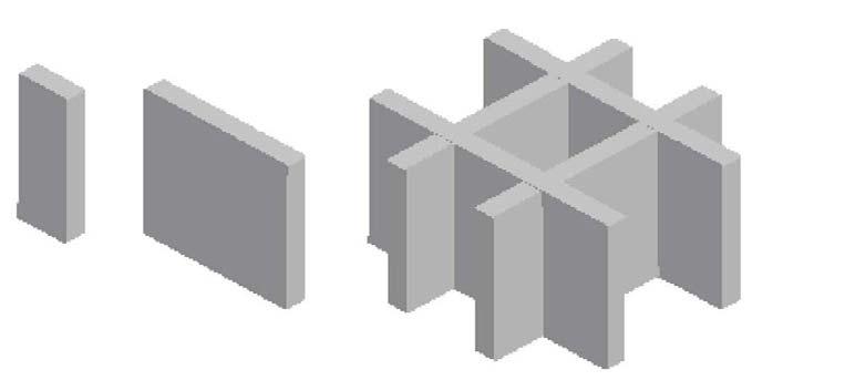
2 What is Cutter Soil Mixing (CSM)? MIXING PLATES


3 Traditional Deep Soil Mixing Methods Utilizes a variety of cutting tools and mixing devices rotating about vertical axes


4 Traditional Methods often utilize Multiple Vertical Shafts Five-shaft Mixing Paddles Three-shaft CFA Three-shaft Mixing Paddles


5 Triple Shaft with Cutting Shoes
6 Development of the CSM method The CSM method, developed from cutter technology, differs from traditional Deep Soil Mixing methods in so far as it makes use of two sets of cutting wheels that rotate about a horizontal axis to produce rectangular panels of treated soil rather than one or more vertical rotating shafts that produce circular columns of treated soil. Key attributes include its ability to penetrate dense strata, and the ability to steer the cutting tool at depth to maintain the designed position. Traditional method CSM method

7 CSM Kelly Mounted System (up to 30m depth)


8 CSM Cable Mounted System 20m+ Quattro Cutter
9 Typical Construction Sequence

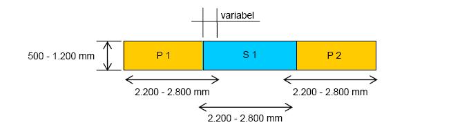
10 Comparison between CSM & traditional DSM methods Waste Effective section Waste Many joints SECANT COLUMN WALL CSM Wall Traditional DSM Wall Waste One joint CSM WALL Waste
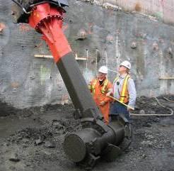
11 CSM Cutter Head o The slurry is added through nozzles between the wheels o About ½ to 3/4 of the necessary quantity on the way down o Balance on the way back to the surface o Preferred rotary direction for cutting as shown compulsory mixer shear plates


12 Materials Handling Automated batch plant and radio controlled slurry delivery system is used to create and deliver a consistent mix at specified water cement ratios and cement concentrations
13 CSM Procedure Cutting & mixing on downward stroke with the injection of a binder or fluidifier that can be: Water. Bentonite. Polymers Cement Other
14 CSM Procedure Thorough mixing takes place on upward stroke with the ongoing injection of binder Moving the cutter up and down will mix layered soils and achieve greater uniformity

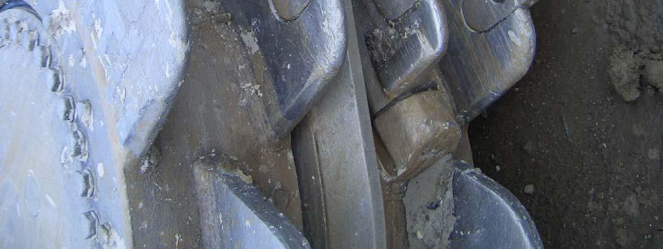
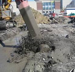
15 Cutting and Mixing


16 CSM Instrumentation External pressure sensor Instruments that read: Verticality on X and Y axes Torque on cutting wheels Wheel speeds The CSM machine is fitted with a complete set of instruments that convey to the operator, in real time, all the information that is needed to monitor and control the quality of the work.


17 CSM - Operator Instrumentation B-TRONIC touch screen in operators cabin
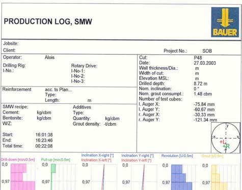

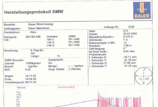

18 DOCUMENTATION Printed reports for analysis

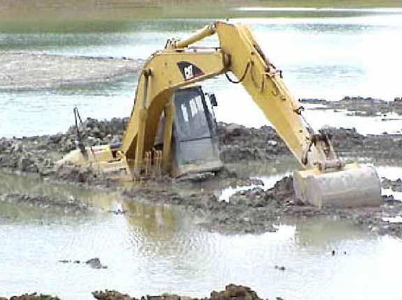
19 Why Do It? Poor Ground Conditions
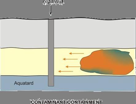
20 Why Do It? Environmental Clean-up


21 Does it work in all types of soil? So far we have used it in: Organic Soils Clays Silts Sands Gravels Cobbles


22 How do you design DSM? How much cement do you need? What is the long term performance? Strength and permeability are generally the main focus of design. The final composition and characteristics of the wall depend on: Cement content Bentonite content Water/Cement ratio Silt and clay fraction of soil Homogeneity of the soil Original Moisture content of the soil Depth of water table Degree of mixing Uniformity of the slurry


23 Quality Assurance/ Quality Control Is preliminary mix design reliable? What should you test? What should you specify? What factor of safety should be used? How do you get representative samples?


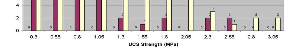
24 Laboratory Test Data - Strength


25 CSM Permeability Permeability 28 Day Target (5,00E-10 m/s) Age Test results: Permeability
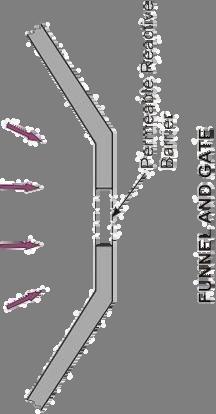
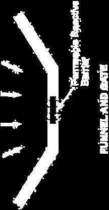
26 Applications Geotechnical Seismic Site Stabilization Foundation Support Shoring Cut-off Walls Slope Stabilization Underpinning Scour Protection Dyke Upgrading Anchoring (up-lift) Other? Environmental Containment In-situ stabilization Funnel and Gate Hydraulic Cut-off In-situ treatment Leachate control Other?


27 Excavation Support BEFORE (during mobilization) AFTER (excavation completed)

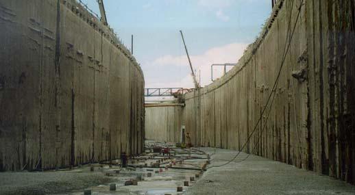
28 Cut-off Walls & Shoring

29 As a Substitution for Conventional Methods to create retaining walls Soldier/King/Berlin pile walls Sheet pile walls Secant/Contiguous pile walls Diaphragm walls

30 Other Applications
31 Other Applications
32 Other Applications
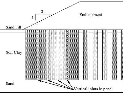

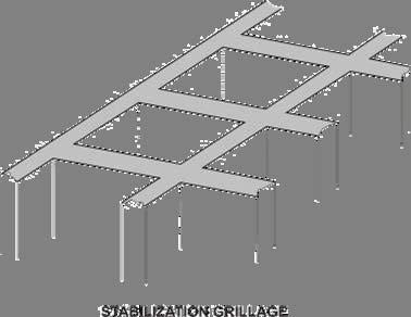
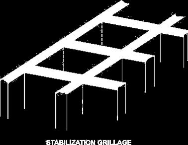
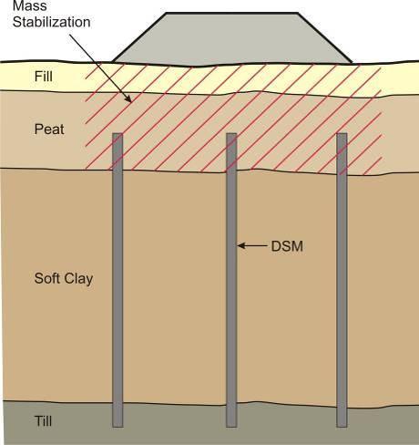
33 Other Applications Support of embankments on soft soils

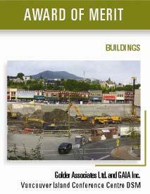
34 North America s First CSM Project Vancouver Island Conference Centre

35 Location: Commercial Inlet historically extended into Nanaimo City Centre, with Commercial Creek flowing into the harbour Snuneymuxw First Nation winter settlement was located on Commercial Inlet, and their main settlement area was located south of the proposed VICC site Nanaimo Harbour 1862

36 Original Site Condition (1858) Nanaimo Harbour (Nanaimo City Archives)
37 Site History In 1862 Vancouver Coal Milling and Land Company built a tramway and wharf into the present site, progressively backfilling the inlet with coal waste. From 1882 onwards, land use was primarily commercial with some light industrial. In the late 1950s/early 1960s the remaining portion of Commercial Inlet was landfilled with highly variable fill. The VICC project spans the original shoreline lands and the reclaimed lands and hence has variable support conditions.

38 Site Partially Filled
39 Geotechnical Challenges Large building loads Weak Soils Deep excavations in relatively poor soils adjacent to the roadways (Highway located south of site) High groundwater table Potentially liquefiable materials in the eastern portion of the site Potential for large lateral displacements of untreated ground during a 1 in 475 year return seismic event Impacts on adjacent buildings and services
40 Preliminary Environmental Options Soil Excavation $5M+ for excavation and disposal Not including: Dewatering $$$$ Shoring $$$$ Place and compact imported fill $$$$ Liability $$$...$$$... Risk Assessment Requires more detailed investigation and delineation of contaminated soils Some soil removal, but most soils remain in-situ Cut-off walls required to prevent, or mitigate offsite migration of contaminated groundwater
41 Preliminary Geotechnical Options Piled Foundations (~ $7.2 M) Stone Columns (used on the Library Building) (~ $4 M + disposal costs for water and spoil)) Bulk Excavation and Replacement with Structural Fill (+ $10 M estimated) Soil stabilization using a combination of deep and shallow mixing processes and shallow compaction methods (~ $3 M)
42 CSM Solution for both Environmental and Geotechnical Issues Uses proven and established technology Provides axial support for the structural loads within the existing poor fill areas Provides lateral stability of the fills during design seismic shaking Provides containment of the contaminated groundwater and soil, thereby reducing offsite disposal requirements (estimated 85% reduction in off-site disposal) Relatively fast Generates low vibrations, in consideration of adjacent sensitive facilities

 and ALLU shallow")
43 North America s First CSM Project Vancouver Island Conference Centre A complete ground engineering solution using Deep Soil Mixing, Rapid Impact Compaction (RIC) and ALLU shallow soil mixing

44 North America s First CSM Project Vancouver Island Conference Centre

45 North America s First CSM Project


46 North America s First CSM Project Vancouver Island Conference Centre Acurate placement of CSM panels allows for optimized design layouts or the ability to work around obstructions (utilities, piles, or other structures) Complete mixing of the in-situ soil with a cement slurry results in an intact soil cement column

47 North America s First CSM Project Vancouver Island Conference Centre


48 North America s First CSM Project Vancouver Island Conference Centre
49 BUILDING A BETTER WORLD: YOUR WORLD. By respecting your concerns, and those of the environment, in Canada and around the globe. THANK YOU!