How-to: Commissioning Design Reviews for the Building Envelope
|
|
|
- Reginald Porter
- 5 years ago
- Views:
Transcription
1 AABC Commissioning Group AIA Provider Number How-to: Commissioning Design Reviews for the Building Envelope Course Number: CXENERGY1625 Stevan Vinci, BECxP, LEED AP, Morrison Hershfield Maurya McClintock, Associate AIA, LEED AP, MCC Facades April 12, 2016
2 Credit(s) earned on completion of this course will be reported to AIA CES for AIA members. Certificates of Completion for both AIA members and non-aia members are available upon request. CES for continuing professional education. As such, it does not include content that may be deemed or construed to be an approval or endorsement by the AIA of any material of construction or any method or manner of handling, using, distributing, or dealing in any material or product. Questions related to specific materials, methods, and services will be addressed at the conclusion of this presentation. This course is registered with AIA


3 Copyright Materials This presentation is protected by US and International Copyright laws. Reproduction, distribution, display and use of the presentation without written permission of the speaker is prohibited. Morrison Hershfield Corporation McClintock Façade Consulting LLC
4 Course Description This session provides an overview of the standards relating to BECx, from design phase activities to design reviews, providing full-wall elevation examples showing the transition from below grade to above grade and to the roof. Attendees will learn how to trace the various enclosure barriers (air, thermal, moisture, and vapor) to ensure continuity throughout the whole enclosure.
5 Learning Objectives At the end of the this course, participants will be able to: 1. Learn how to determine the building enclosure control layers water, thermal, air, and vapor. 2. Learn how to review the various enclosure control layers to ensure continuity. 3. Learn how to review the enclosure design against the requirements outlined in the owner s project requirements. 4. Learn some of the issues associated with some common enclosure details in various climate zones.

6 What is the Building Envelope? 6 The assembly of components that separates the interior and the exterior environment.


7 Envelope Continuity 7 The assembly of components that separates the interior and the exterior environment.
 Wind Driven Rain Wind Blown Snow Snow & Ice Accumulation UV Exposure Impact")
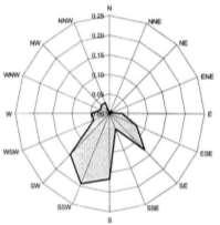
8 Outdoor Environment 8 Temperature (Extremes & Difference) Humidity Rainfall (peak & total) Wind Driven Rain Wind Blown Snow Snow & Ice Accumulation UV Exposure Impact Contaminants

9 Indoor Environment 9 Temperature and Humidity Requirements determined by occupancy Controlled by HVAC system
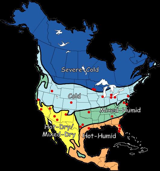
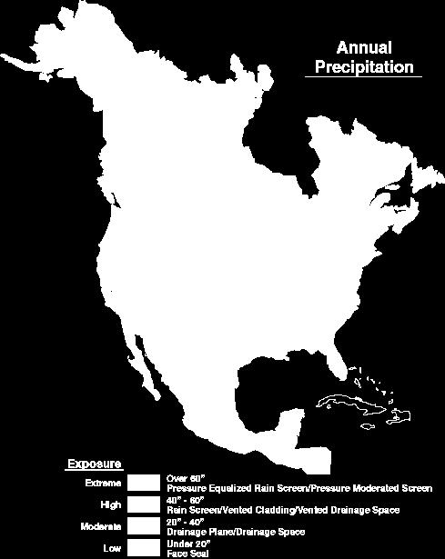
10 Climatic Conditions 10
11 Building Envelope Design Factors 11 Resist imposed loads Control rain penetration Control air flow Accommodate movement Control heat flow Control vapour diffusion Provide security Control radiation Control fire Control sound transmission Be durable Be aesthetically pleasing Be economical
12 Building Envelope Design Factors 12 Resist imposed loads Control rain penetration Control air flow Accommodate movement Control heat flow Control vapour diffusion Provide security Control radiation Control fire Control sound transmission Be durable Be aesthetically pleasing Be economical

13 Control layers or barriers 13 Water Barrier (most important) Rain Shedding Surface Lapping of element Drips directing water off walls How does water run off horizontal elements Internal moisture barrier Drain path to outside Lapping of elements Venting of cavities Air barrier Continuous Structurally supported Provision for relative movement
14 Control layers or barriers 14 Thermal Barrier (Insulation) Continuity/thermal bridges Keeping interior surfaces above dew point Outside of structure if possible Vapor Barrier (Humidity Control) On warm side of insulation


15 Water Barrier - Rain Penetration Control 15 Driving forces: momentum capillarity gravity air pressure Resistance diversion drainage drying


16 Water Penetration Failures 16 Wall Failure Window Failure


17 Steel Stud Wall Failures 17 Not limited to a wood frame construction

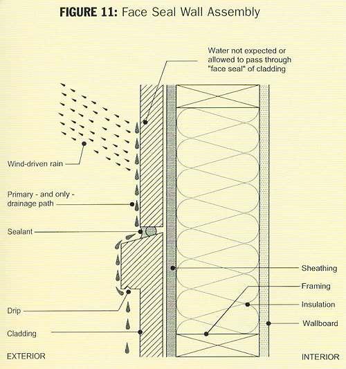
18 Water Barrier Types - Face Sealed Water Barrier 18 Cladding is only barrier First and only line of defense Examples: EIFS Precast panels Masonry mass wall
19


20 Face Sealed Water Barrier 20 Face-Sealed Exterior Walls: least water resistant assembly Relies on sealant joints Unforgiving when water penetration occurs Reliable only in very dry climates/locations. Low Slope Roofs: ultimate example of barrier design Minimum joints Layered approach Limited penetration Slope pitched toward drain Storage or Mass Wall: Oldest strategy Relies on absorption and evaporation Can be suitable for all climates or locations Main limitation is joints and interfaces.
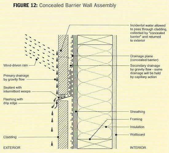
21 2. Concealed Water Barrier 21 Uses a WRB membrane touching cladding Weather Resistive Barrier Non-absorbent claddings: Vinyl siding, metal siding Use at walls with low or medium exposure Absorbent claddings: Cladding in contact with WRB stucco, wood, fiber-cement siding Use at walls with low exposure only
22 22


23 Concealed Water Barrier 23 Moisture damage resulting in corrosion and failure of attachments
 between cladding and")

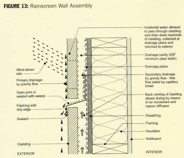
24 3. Ventilated Concealed Water Barrier 24 Include drainage cavity (airspace) between cladding and drainage plane Airspace should be 3/8 for drainage, 1/2 or more for ventilation aka Rainscreen Wall 24
25


26 Air Leakage Control 26 Vapor Diffusion vs. Air Leakage


27 Air Leakage Problems 27 Wood Framed Party Wall Air Exfiltration Wood Rot & Moisture- Induced Deterioration


28 Air Leakage Problems 28 Failure at Seams of Air Barrier
29 Air Pressure Difference 29 Stack Effect Wind Mechanical Pressurization


30 Thermal Barrier 30 R-value measures resistance Rarely includes thermal bridging or three dimensional heat flow Polyisocyanurate R Concrete Masonry Units R Mineral Wool R4.2 Gypsum Wallboard R


 Convection")
31 Heat Transfer 31 Heat travels into a building through three methods. Conduction (thermal bridge) Convection (air leakage) Radiation


32 Thermal Problems 32 Stud shadowing on inner and outer faces Photo of stud shadowing outside


33 Thermal Problems 33 Surface Mold Growth

34 Isolating Thermal Bridges 34 Some thermal bridges cannot be avoided Three options Encapsulate in airtight insulation i.e. spray foam Insulate with airtight insulation to a point beyond likely dew point Increase heat flow to thermal bridge to minimize risk of condensation
 35")


")

35 Vapor Barrier (Retarder) 35 Internal Humidity Source Purpose of Vapor Retarder: Prevent humidity (water vapor) from reaching cold surfaces and condensing inside the wall


 just as it does")
36 Humidity Removal 36 Mechanical Spot Ventilation Dehumidification Air Conditioning Passive Occurs when air contacts a surface colder than the dew point Occurs on a cold interior surface and interstitial surface (within an envelope assembly) just as it does on your car at night


37 Consequence of Poor Control 37 Vapor diffusion leading to condensation behind vinyl wall paper in air conditioned interiors in a hot humid climate.


38 Controlling Movement of Humidity 38 Vapor Retarder Impermeable (no drying) Class I: Permeance 0.1 Perms Polyethylene films, Aluminum foil & sheet metal, Elastomeric membranes, Bituminous or rubber membranes, Extruded polystyrene, Oil based paints, Glass Semi-Impermeable (minimal drying) Class II: Permeance Perms Semi-Permeable Permeance 10 Perms Plywood & OSB sheathing, Expanded polystyrene (bead board), Fiber-faced isocyanurate insulation, Heavy asphalt impregnated papers, Latex based paints Permeable Permeance > 10 Perms Unpainted gypsum wallboard, Un-faced fiberglass insulation, Unpainted stucco or cement sheathing, Lightweight asphalt impregnated paper, Spun bonded polyolefin house wraps

39 Questions? 39
40 BECx Design Review 40 Purpose To identify performance, durability of constructability concerns in the design stage as well as meeting the Owner s Project Requirements. Contractual Clients Owners Architects Contractors Other Clients Future owners Authorities Having Jurisdiction Insurers/Warranty Providers
41 BECx Design Review 41 Typical Scope Environmental Separations Roofs and decks over conditioned space Opaque Walls Glazing At grade waterproofing Below grade walls Slabs on Grade Other Waterproofing Balconies Canopies Suspended slabs on underground parking areas
42 Considerations 42 Elements proving control of Heat, Air and Moisture flows Allowance for relative movement of structure and enclosure element Durability Constructability Understanding structural attachment


43 Process 43 Understand the design intent(s) of space and each enclosure system Understand the geometry of the building and use of each enclosure system Review all transition details thinking in 2D then 3D Identify missing details Transmit Information to Design Team on behalf of the Owner
44 Understanding the Intent 44 Of the Building Understand the interior and exterior environmental conditions and exposures Be aware of any special requirements Of the Enclosure Assemblies Plane of air tightness Rain shedding approach Last line of defense against moisture entry Mechanism for removal of incidental moisture
45 Initial Drawing Review: 45 Review plans, elevations and sections to understand geometry Conditioned and unconditioned spaces Changes in floor plan creating horizontal enclosure elements Changes in systems used Slopes on all horizontal surfaces Location of drains, scuppers, and weep holes Unprotected doors Problematic details Balcony edges Curbs into walls Through wall flashing and shelf-angles Expansion and control joints
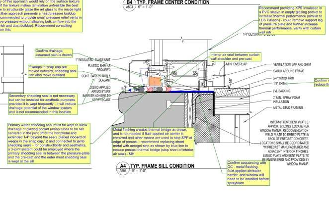
46 Window-wall head/sill detail A 46
47 Window-wall head/sill detail A 47 Primary water Secondary water Air Thermal
48 Window-wall head/sill detail B 48
49 Window-wall head/sill detail B 49 Primary water Secondary water Air Thermal
50 Window-wall head/sill detail C 50
51 Window-wall head/sill detail C 51 Primary water Secondary water Air Thermal
52 Barrier Continuity 52
53 Barrier Continuity 53 Primary water Secondary water Air Thermal
54 Barrier Continuity 54 Secondary drainage +Air seal continuity? Secondary drainage weep? (where is control line?) Air seal continuity? Primary water Secondary water Air Thermal
55 Shop Drawings 55
56 Shop Drawings 56 Primary water Secondary water Air Thermal
57 Shop Drawings 57 Primary water Secondary water Air Thermal
58 Barrier Continuity (plan) 58
59 Barrier Continuity (plan) 59 Primary water Secondary water Air Thermal
60 Barrier Continuity (plan) 60 Primary water Secondary water Air Thermal
61 Barrier Continuity (plan) 61

62 Barrier Continuity (plan) 62
63 Parapet 63
64 Parapet 64

65 Parapet 65


66 Barrier Continuity Example 66
67 This concludes The American Institute of Architects Continuing Education Systems Course Stevan Vinci, CET, LFA, LEED AP BD+C O+M HOMES, BECxP, CxA+BE Principal, Senior Sustainability and Building Science Specialist Morrison Hershfield Corporation Maurya McClintock, Associate AIA, LEED AP Director McClintock Façade Consulting LLC