IR Cameras and Building Insulation Performance
|
|
|
- Darren Robbins
- 5 years ago
- Views:
Transcription
1 IR Cameras and Building Insulation Performance Jay Bowen Infrared Training Center FLIR Systems, Inc All images are property of ITC and FLIR Systems, Inc
2 Outline Infrared Inspection of Building Envelopes Presenter: Jay Bowen, FLIR Systems, Inc. St. Charles Room A With increasing energy costs, thermal imaging cameras have quickly become prevalent for commercial and residential building inspection. Building structures commonly exhibit quality and performance problems caused during construction and maintenance that can impact energy performance and, in some cases, render them dangerous. Regardless of the building type involved, infrared imaging has been shown to provide remarkable, nondestructive information about construction details and building performance. This session will discuss the numerous applications for thermal imaging technology currently being used to inspect building envelopes. These include validation of structural details, verification of energy performance (conduction and air leakage), location of moisture intrusion, and the identification of structural and system degradation of roofs and facades. Examples will be given for each application and the basic conditions required will be discussed.


3 Cameras Some cameras were simply easier to use???

4 Camera Sample Images from AGA 680 Circa 1972


")

5 Camera Detectors 640x480 1 IR Image 320x240 4 IR Images (1/2 the distance to get same resolution) 160x IR images (1/4 the distance to get same resolution)
 shortcuts Good training can get & keep you on")
6 Sometimes you can t make it simple IR images are easy to get, often difficult to interpret The obvious isn t always obvious Don t try to make IR easy with simple (but wrong) shortcuts Good training can get & keep you on track

7 IR is Magic Just point the IR camera at a target Move the measure tool where needed Get an accurate temperature It s that easy Or is it?


8 Thermographic Cameras Must be within a correct distance Must be focused thermally and optically Must enter measured object emissivity Must enter reflected temperature Must be in the correct range


9 Target Resolution or Spot Size Small targets Large targets


10 Thermal Tuning and Focus Proper Tuning Inadequate Tuning


11 Lens Change for Distance 24º 7º 12º 80º 45º Some cameras are able to change lenses to assist resolution.

 equals one High means")
12 Thermal Emissivity Efficiency of objects to radiate heat For opaque objects: Emissivity ( ) plus reflectivity ( ) equals one High means low and vice versa


13 Target Surfaces Wood Barrels High Emissivity & Low Reflectivity Shiny Metal High Reflectivity & Low Emissivity
14 IR Camera Workings Capture emitted plus reflected energy Subtract off the reflected energy, Use object emissivity to normalize to a blackbody Find temperature in a calibration table Map to color palette Display
15 Target Interpretation Still or static Moving or dynamic


16 Focus Focused = Accurate Unfocused = Inaccurate

17 Scan Rate Better


18 Environmental Accuracy From this To this Camera should remain accurate through it s entire operating range

19 Review Today s cameras are easy to operate Understanding IR is as important as understanding your equipment You need proper training to be a thermographer Experiment! Practice!

20 Need Ideas?????????????????

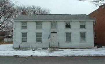
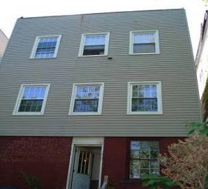
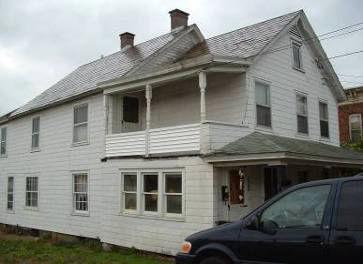
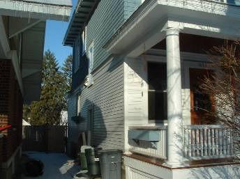
21 Typical Existing Homes
22 Use Of IR Camera For Building Shell Analysis: Identifying framing and insulation integrity of the building envelope Air leakage out of and movement through the building shell QA/QC of Corrective Measures installation of insulation and infiltration reduction measures Repair of same
23 Viewing Thermal Images Of Buildings Image is only the surface temperatures of object in picture (but beware!) It is the effect of the materials beneath the surface on the surface temperature that make you think you are seeing through materials. You may think you see an image of something beneath the surface but you are viewing the last surface only. It is our ability to interpret the images and the information that is of value!
24 Use Caution When Evaluating Exterior Wall Images Insulating sheathing materials can skew interpretation by moderating the surface temperature of the interior wall. This is particularly true with a brick façade. Examples of Insulating Sheathing: Urethane Panels Celetex Extruded Polystyrene BOTTOM LINE: You may still need to do selective sampling to physically determine what is in the wall cavity!!!
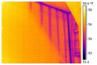
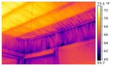
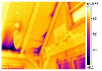
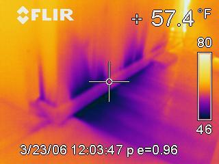
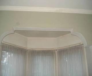
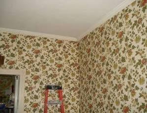
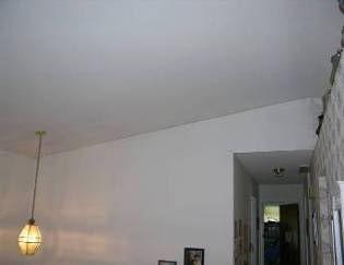
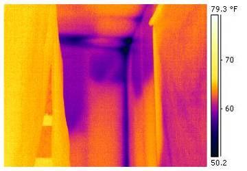
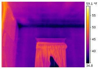
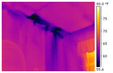
25 Analyzing Shell Framing And Insulation Look For Inconsistencies In The Thermal Boundary In a well insulated wall, the framing may not be as obvious. However, you will notice a dark line where 2 or more surfaces meet (wall ceiling, wall-wall, and at corners). This is common point of thermal boundary issues.

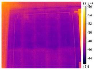
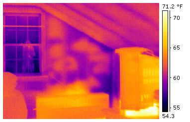
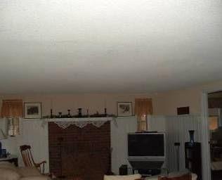
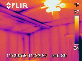
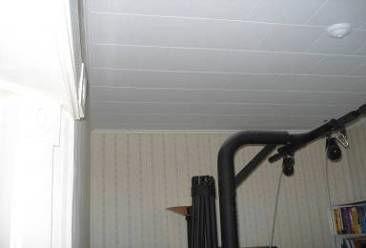
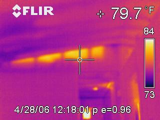
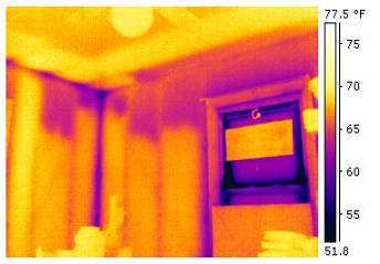
26 Walls And Ceilings

27 Missing Insulation Is Evident With The IR Camera

28 Poorly Installed Fiberglass Batt and Blown Insulation
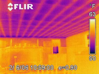
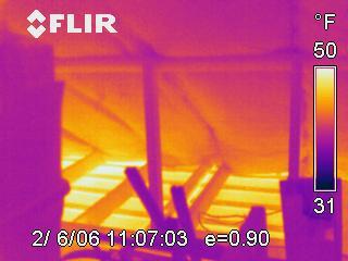
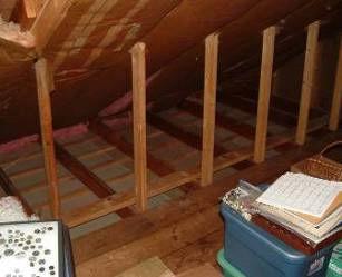
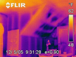
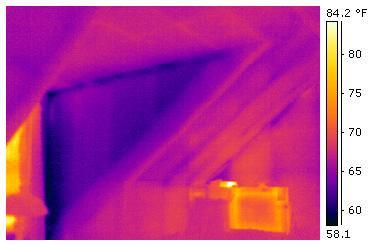
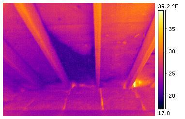
29 No Insulation In Attic
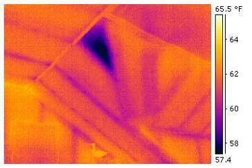
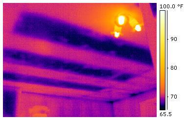
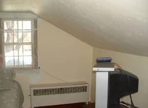
30 Dormers!

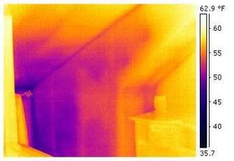
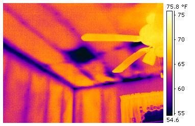
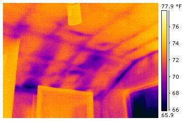
31 Knee Walls

32 Flat Roof Images


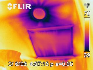
33 Attic Hatches The top image is a pull-down stairway. The bottom image is also a pull-down staircase. Why are these images different?

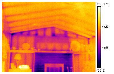
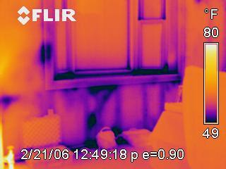
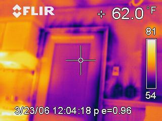
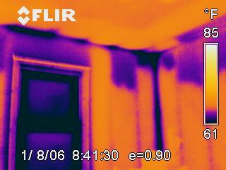
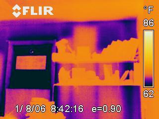
34 Fireplaces And Intersections With Exterior Walls
35 Air Infiltration = Heat Exfiltration Common sources of air infiltration Around Doors Balloon Framing Rim Joists at the top of Foundation Walls Exterior Wall Outlets and Switches Bath and Kitchen Exhausts Vertical Intersection of Walls and Horizontal Intersection of Walls and Ceilings Plumbing and Electrical Chases


36 Air Infiltration: With And Without a Blower Door Infrared image doesn t show air leakage at top of cathedral ceiling. Why? Because air leaking out shows no temperature difference from inside With Blower door, air leakage becomes obvious because air leakage is reversed

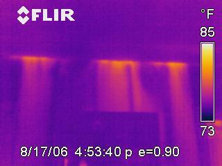
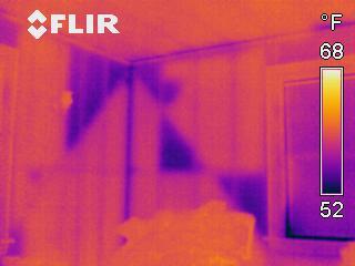
37 Blower Enhanced Images


38 Blower Enhanced Images Images courtesy of Energy Construction, LLC. Used with permission.
39 Its Not Always Winter!!! When outside temperature rise above indoor temperatures infrared images completely change. Exterior temperature differences will no longer be darker. Awareness of this is critical in making correct interpretations

40 Summer Changes Everything

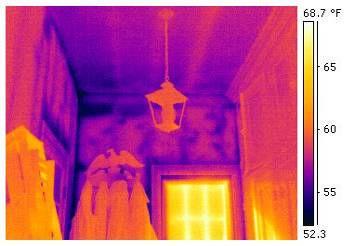
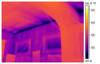
41 Wall And Ceiling Interface

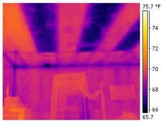
42 Watch for Solar Loading


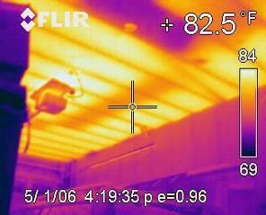
43 Heat And Moisture Escaping Into Attic

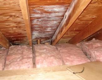
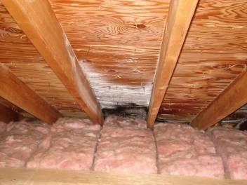
44 Moisture In An Attic


45 Moisture Within Building Materials The key to remember is that moisture can be mistaken for cold air infiltration. Therefore, you have to validate those dark areas for the presence of moisture!!!
46 Improperly Blown & Differential Settling of Insulation
47 Improperly Blown Wall Cavities

48 Check for Continuity of Thermal Boundary And Eliminate Problems Down the Road
49 Standards C Location of Wet Insulation in Roofing Systems Using Infrared Imaging C Thermographic Inspection of Insulation Installations in Envelope Cavities of Frame Buildings E Air Leakage Site Detection in Building Envelopes and Air
50 Standards (Best) Time of day considerations (non sunny) Minimum temp differential (18F) Minimum distance to size of target or MFOV Wind speed considerations (none) Angle of view (perpendicular)

51 Conductivity and R value Insulation material has k=.27 or R=13 Wooden stud has k=0.97 or R=3.6 Wooden studs conduct more energy than the insulation appears cold on the inside when the heat flow is away from the viewer


52 Conductivity and R value Insulation material has a low k=.27 Metal stud has a high k=346.9 Metal studs conducts allot more energy than the insulation appears cold on the inside Cold on the inside? Hot on the outside?
53 R value estimates using Temp Diff

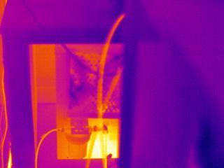
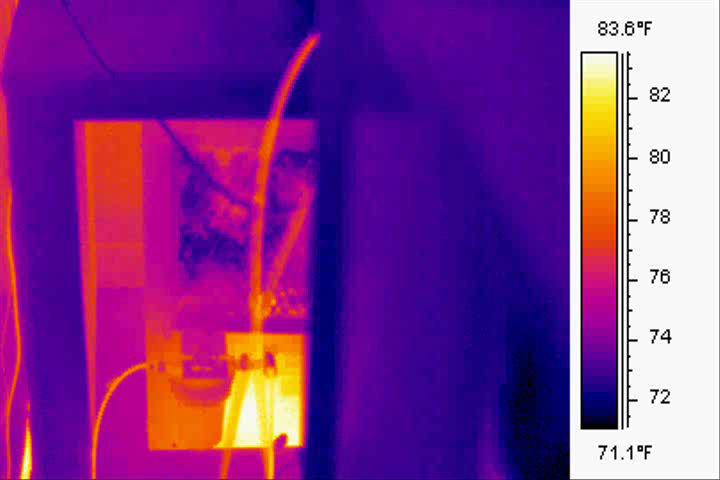
54 Temp Diff Example Outside air = -5 of Emissivity 0.93 Reflected Apparent Temperature 72.3 F Atmospheric Temperature 70.0 F Image Date 1/19/2008 Image Time 9:10:07 AM Ar1 Average Temperature 69.9 F Ar2 Average Temperature 67.4 F Ar3 Average Temperature 67.7 F Temp diff O I=-5 70 = 75 IW-IA = = 2.6
55 R value estimates using Temp Diff 2.6 & 75

56 R value Estimates Wall Stud Interior air boundary Wallboard Insulated Sheathing Wood siding Exterior air boundary Insulation Total =
57 R Value Summary Very Difficult to do Prone to error Image could have infiltration or a thermal bridge involved.

58 An R Value Calculator Developed by Dr. Bob Madding of Infrared Training Center

59 Thank You Very Much!