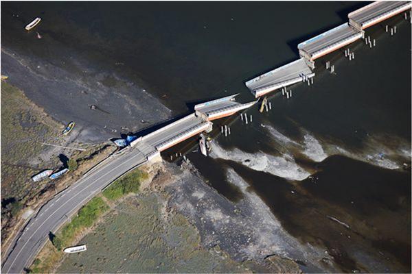
1. Bridge damage due to earthquake
|
|
|
- Karen Richard
- 5 years ago
- Views:
Transcription

1 Outline 1. Bridge damage to earthquake 2. Seismic analysis and evaluation of existing bridges 3. Bridge strengthening methods 4. Cyclic load test of bridge using FRP strengthening technique 5. Strengthening of columns using FRP 6. Application of FRC in ductility improvement of bridge structures 1


2 1. Bridge damage due to earthquake Potential Earthquake Sources Tectonic Plate Boundary Bangkok km Megathrust Sunda subduction zone, where Indo-Australian plate moves toward Eurasian plate at a rate of mm/year Indo-Australian plate Eurasian plate Generates frequent and large earthquakes. Nearest distance from this fault to Bangkok is km. Largest recorded quake is M w = 9.1 Sumatra-Andaman Earthquake in 2004, a cause of destructive tsunami. 2


3 Potential Earthquake Sources Earthquake Sources Crustal Faults There are 13 known active faults in Thailand. 3
 : During 1912 to 2007, ~15,000 earthquakes")


4 Pan Hospital in 1995 Earthquakes IN Thailand (Mw 5) : During 1912 to 2007, ~15,000 earthquakes with M w 3.0, including foreshocks & aftershocks were recorded near Thailand. Year Source Location Magnitude Damage 1935 Naan 6.5 Felt in BKK 1975 Taak Kanchanaburi 5.3,5.9,5.2 (Sri Sawat fault) 1995/96 Chiang Rai 5.1/5.5 Damage to buildings 1995 Phrae 5.2 Mae Lao Earthquake 5 May


5 Masonry infill wall failure 5

6 6


7 7


8 8


9 Bridge pier collapse 9


10 Bridge pier collapse Unseating 10

11 Unseating Unseating 11


12 Bridge pier collapse- Flexure failure Bridge pier collapse- Flexure failure 12


13 Bridge pier collapse- Bar buckling Bridge pier collapse- Shear failure 13


14 Bridge pier collapse- Shear failure Joint failure 14


15 Joint failure Beam failure 15

16 Abutment failure 2. Seismic analysis and evaluation of existing bridges : Compare structural capacity and demand from earthquake 4 major methods 1. LSP Linear static procedure 2. LDP Linear dynamic procedure 3. NLSP Non linear static procedure 4. NLDP Non linear dynamic procedure 16

17 Non linear static procedure using CPM o ต วอย างของ Capacity Spectrum Method Demand vs Capacity 17
18 Bridge evaluation procedure using Capacity Spectrum Method (CPM) o Analysis for seismic demand from earthquake using Linear Elastic Time History Analysis and convert it into response spectrum result or Demand Spectra o Calculate structural capacity using pushover analysis method to obtain force-lateral displacement of the bridge o Compare capacity and demand in the same chart. The seismic resistance capacity of structures could be directly obtained form the chart 3. Bridge strengthening methods Reinforced concrete jacketing Steel plate jacketing FRP jacketing - Carbon fiber reinforced polymer (CFRP) - Glass fiber reinforced polymer (GFRP) - Aramid fiber reinforce polymer (AFRP) 18


19 RC Jacketing 19
 NEW.wmv การว บ ต เน องจากแรงด ดVDO\S1L WMV HD 720 30p.avi การว บ ต เน องจากแรงเฉ อนVDO\S3S WMV HD 720 30p.")
20 การเปร ยบเท ยบการว บ ต ของเสาท ม การต อทาบและไม ต อทาบ VDO\video total Zoom Crack column S1 and S1splice (WMV HD 720 ) NEW.wmv การว บ ต เน องจากแรงด ดVDO\S1L WMV HD p.avi การว บ ต เน องจากแรงเฉ อนVDO\S3S WMV HD p.avi 20


21 21


22 Steel plate jacketing 22

 3.")
23 FRP jacketing What is FRP? There are three types of fiber 1. Carbon fiber reinforced polymer (CFRP) 2. Glass fiber reinforced polymer (GFRP) 3. Aramid fiber reinforced polymer (AFRP) 23


24 Stress strain relationship of different fiber type Type of CFRP SHEET Advantages: 1. Light weight 2. Easy to install 3. Environmental Durability PLATE ROD Disadvantages: 1. Expensive 2. Fire vulnerability 3. Require installation expert 24


25 25
 4000 ksc Strain FRP design for columns Longitudinal direction for enhancing moment resisting capacity Transverse direction for: - increase compressive strength due to confinement effect -")
26 Stress ksc Design Stress Limit for CFRP(strain = 0.004) 4000 ksc Strain FRP design for columns Longitudinal direction for enhancing moment resisting capacity Transverse direction for: - increase compressive strength due to confinement effect - increase shear strength by truss action It is more effective to increase the confinement when used in circular column compare to rectangular column The strength and ductility of concrete will increase when wrapped transversely by CFRP 26


27 Collapse Behavior of a cylinder wrapped by FRP Concrete cylinder with compressive strength of 24 MPa Concrete cylinder wrapped by 1 layer CFRP. Compressive strength 40 MPa 4. Cyclic load test of bridge using FRP strengthening technique TYPE OF BRIDGE Pile Bent with 4 columns with 1-layer bracing Pile Bent with 4 columns with 2-layer bracing 27
28 CLASSIFICATION OF PILE BENT BRIDGE TYPE 3-span bridge 5-span bridge EXPERIMENTAL PROGRAM Test 4 half-scale model ทดสอบเสา 4 ต นแบบลดขนาด (half-scale model) Strengthening Method - GFRP- commercially available in Thailand - Use different type of strengthening location 28


29 DETAILING OF BRIDGE SPECIMEN FOUNDATION OF TEST BRIDGE 29


30 TEST BRIDGES specimen Strengthening Strengthening Approach Test time Material C1r_GFRP GFRPP Strengthening after test 1 Month C2_GFRP GFRP Strengthening before test 1 Month C3r_GFRP GFRP Strengthening after test 1 Month C4_GFRP GFRP Strengthening before test 1 Month PREVIOUS BRIDGE COLUMN DAMAGE 30


31 STRENGTHENING BY GFRP TYPE1 STRENGTHENING BY GFRP TYPE2 31


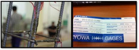
32 CONSTRUCTION STAGE STRAIN GAGE LOCATIONS Setup Strain Gauge Longitudinal = 34 Ea. Strain Gauge Transverse = 12 Ea. Total Strain Gauge = 46 Ea. 32


33 LVDT LOCATION Setup LVDT = 20 Ea. CYCLIC LOAD TEST SETUP 33
34 DISPLACEMENT HISTORY Drift (%) Number of Steps C1r_GFRP 34


35 Actuator installation Transverse displacement prevention 35


36 Sensors Load cell Displacement sensor Stain Gage Reference name of strain gages 36


37 การต ดต งLVDT Measurement of curvature and shear deformation การต ดต งLVDTเพ อว ดการเส ยร ปเน องจากแรงเฉ อน ในคาน Lateral Drift +0.50% Cycle 1 Compressive strength ksc 37


38 Lateral drift +0.75% cycle 1 Lateral drift +1.5% cycle 1 38


39 Lateral force displacement relationship STRENGTHENING PROCEDURE FOR CFRP AND GFRP 39


40 1. Grind 4 corner of the columns and beam. 2. Use clean cloth to clean the concrete surface 3. Mix Epoxy Resin using the proper mix ratio according to manufacturing recommendation 3. Use a brush to paint epoxy resin on the target surface 40


41 4. Wrap the fiber and use the roller to roll on the fiber surface to make sure that the fiber perfectly attach to the concrete surface. Paint the fiber with epoxy before wrapping another layer. Lateral drift +0.50% round 1 41


42 Lateral drift +0.75% round 1 Lateral drift +1.50% round 1 42


43 Lateral drift +3.50% round 1 Lateral force displacement relationship 43


44 Comparison of Lateral force displacement relationship C2_GFRP 44


45 VDO\Pile bent 2 WMV HD p.wmv 45


46 C3r_GFRP 270 ksc 170 ksc 170 ksc 46


47 VDO\Pile bent 3 Before.mpg After Strengthening 47
48 VDO\After Repair (Pile Bent3).mpg C4_GFRP 48


49 150 ksc 150 ksc 150 ksc VDO\Pile bent 4.mpg 49


50 Durability Proof of GFRP. undergoing research Durability test of GFRP - Weight Loss - Tensile Strength Loss Mixtures Cement Extract Mixtures Sodium Hydroxide (NaOH) 50


51 Weight Loss Test 5 cm Tensile Strength Loss Test Steel plate Fiber + epoxy Tensile Strength Loss Test Parameters to be studied - PH of solution - Temperature 51
 Shear Span (mm) Aspect Ratio Splice Detailing Axial Load Ratio Mode of Failure")


52 5. Strengthening of columns using FRP Col. bxh (mm) Shear Span (mm) Aspect Ratio Splice Detailing Axial Load Ratio Mode of Failure Remarks S1 CFRP 250x No splice 0.2 Flexure GFRP wrap S1 SCFRP 250x db 0.2 Flexure GFRP wrap S2 CFRP 250x No splice 0.2 Flexure shear GFRP wrap S2 SCFRP 250x db 0.2 Flexure shear GFRP wrap S3 CFRP 250x No splice 0.2 Flexure Shear GFRP wrap S3 SCFRP 250x db 0.2 Flexure Shear GFRP wrap V M Gravity Load (P) F P h h M P Contraflexure Point V H=2.05m 52


53 6. Application of FRC in ductility improvement of bridge structures


54 Objective To improve the ductility of non-ductile RC columns using steel reinforced concrete (SFRC) Test Programs C1 without SFRC S1 with SFRC 1% by volume mm hookended steel fiber


55 Test under Displacement Control Condition 109 Loading scheme At 0.5% Drift 110 C1 S1 55

56 At 1% Drift 111 C1 S1 At 3% Drift 112 C1 S1 56


57 At 3.5% Drift 113 C1 S1 At 8% Drift 114 S1 57
58 Hysteresis loop comparison Column 0.5% FRC Column S1 Column 1.00% FRC Lateral Load (kn) DRIFT (%) u P mcol yf Test Results Column C1 S1 max load, (kn) deflection at yield(mm) load at yield 1 (kn) deflection at yield(mm) load at failure (kn) deflection at failure (mm) displacement ductility, Mode of failure Flexure Flexure


59 59


60 เสาท ไม ม การเสร ม BRR เสาท ม การเสร ม BRR 60
61 ขอบค ณคร บ 61