The Project Manual and Project Drawings dated February 2013, for the above referenced project, are amended by this addendum.
|
|
|
- Ferdinand Allison
- 5 years ago
- Views:
Transcription
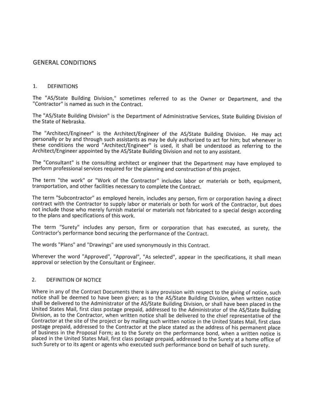
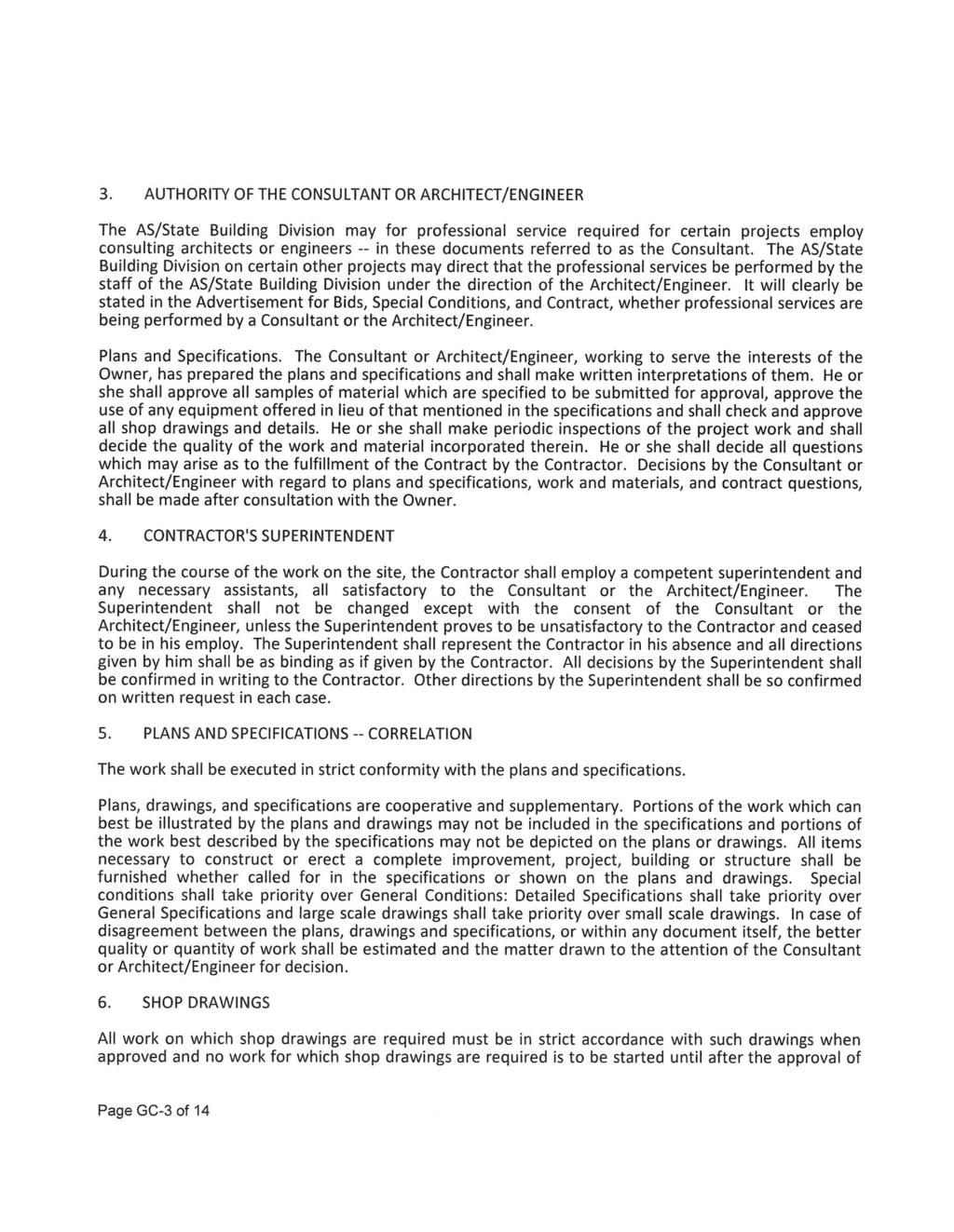
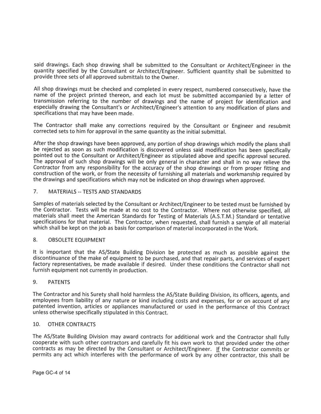
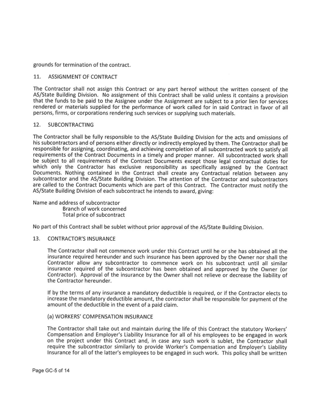
1 ADDENDUM NO. 2 Western Nebraska Veterans Home Kitchen HVAC Renovation 1102 W 42 nd Street Scottsbluff, Nebraska February 2013 / OA Project No Design Professionals: Olsson Associates Mechanical and Electrical Engineers DATE OF ISSUANCE: March 12, 2013 Bid Opening Date, Time & Location: March 28, 2013, 2:00 PM CT, State of Nebraska, AS/State Building Division, Executive Building, 521 South 14 th Street, 5 th Floor, Lincoln, Nebraska The Project Manual and Project Drawings dated February 2013, for the above referenced project, are amended by this addendum. NOTICE: This Addendum is issued to all interested prospective bidders as an amendment to the project manual or other parts of the bidding (contract) documents for the above named project. Reference to this Addendum must be included in the Bid proposal. The information contained herein shall be fully incorporated into the contract documents as though originally included therein. PROJECT CHANGES 1) General Conditions Section, Pages 1-13 Delete the General Conditions in its entirety and replace with the attached General Conditions (pages GC 1-14). 2) Refer to Specification Duct Insulation Delete this Section in its entirety and replace with the attached Section Duct Insulation. 3) Prior Approvals The following manufacturers are approved for bidding purposes, subject to the provisions of the specifications and drawings. Specification Section Grilles, Registered, Diffusers: add Krueger 4) Refer to Sheet G2 Phasing Plans Amend General Note A to read: Contractor shall remove, store protected from elements, 5) Refer to Sheet FS1 Kitchen Equipment Plans, Elevations & Schedule Add Sheet FS1 Rev 1 to the set. 6) Refer to Sheet M1 First Floor HVAC Plans Amend General Note A to read: In kitchen (including side room of kitchen to west, and south of Food Storage), Replace General Note E with: Before excavating for this project, the contractor shall perform locates of all necessary utilities. One Call will not necessarily locate on private property. Replace General Note I with: All duct seams shall be sealed, see specifications. Page 1 of 2
2 Amend Sheet Note 8 to read: Relocate condensing units, demo old pads, add new poured housekeeping pads. Amend Sheet Note 9 to read: Provide new poured concrete pad, slope as indicated at minimum 1/8 per ft. Add to end of Sheet Note 15: Extension shall have rain cap. 7) Refer to Sheet M2 Roof HVAC Plans and Plumbing Plans Add General Note S: Roof work shall be done to maintain existing roof warranty of kitchen and admin roofs. See attached M2. Add locations of roof duct supports. 8) Refer to Sheet M3 First Floor Plumbing Plans Plumbing Site Plan, add cleanout (below grade) halfway down length of run. See attached M3. See rerouting of domestic water to MAU-1, and addition of bleeder valve. 9) Refer to Sheet M5 Mechanical Details & Legend Detail 1 (Rectangular Duct on Roof), amend Note 1 to read: Space supports a maximum of 6 ft. apart & at every change of direction Details 3 and 7, minimum curb height shall be ) Refer to Sheet M7 Mechanical Schedules Add in Air Handling Unit Schedule, AHU-1: Unit Voltage: 208/60/3 MCA: 60.3 A MROPD: 70 A Add in Air Handling Unit Schedule, MAU-1 Unit Voltage: 208/60/3 Supply Fan Motor 5 HP FLA 14.1 FLA Provide AHU-1 with smoke detector in supply ductwork. 11) Refer to Sheet E1 First Floor Electrical Plans Amend General Note L to read: shall be mounted 46 (to top of device) A.F.F. unless END OF ADDENDUM NO. 2 Each Bidder must acknowledge receipt of all addenda in the space provided on the Bid Form. Page 2 of 2
3 SECTION DUCT INSULATION PART 1 - GENERAL 1.1 RELATED DOCUMENTS A. Drawings and general provisions of the Contract, including General and Supplementary Conditions and Division 01 Specification Sections, apply to this Section. 1.2 SUMMARY A. Section includes insulating the following duct services: 1. Indoor, concealed supply air. 2. Indoor, concealed return located in unconditioned space. 3. Indoor, concealed, Type I, commercial, kitchen hood exhaust. 4. Indoor, concealed warewash exhaust. 5. Indoor, concealed exhaust between isolation damper and penetration of building exterior. 6. Outdoor, exposed supply and return. 1.3 ACTION SUBMITTALS A. Product Data: For each type of product indicated. Include thermal conductivity, watervapor permeance thickness, and jackets (both factory- and field-applied if any). 1.4 QUALITY ASSURANCE A. Installer Qualifications: Skilled mechanics who have successfully completed an apprenticeship program or another craft training program certified by the Department of Labor, Bureau of Apprenticeship and Training. B. Surface-Burning Characteristics: For insulation and related materials, as determined by testing identical products according to ASTM E 84, by a testing agency acceptable to authorities having jurisdiction. Factory label insulation and jacket materials and adhesive, mastic, tapes, and cement material containers, with appropriate markings of applicable testing agency. 1. Insulation Installed Indoors: Flame-spread index of 25 or less, and smokedeveloped index of 50 or less. 2. Insulation Installed Outdoors: Flame-spread index of 75 or less, and smokedeveloped index of 150 or less. Western Nebraska Veterans' Home DUCT INSULATION Kitchen HVAC Renovation Scottsbluff, Nebraska OA No
4 1.5 DELIVERY, STORAGE, AND HANDLING A. Packaging: Insulation material containers shall be marked by manufacturer with appropriate ASTM standard designation, type and grade, and maximum use temperature. 1.6 COORDINATION A. Coordinate clearance requirements with duct Installer for duct insulation application. Before preparing ductwork Shop Drawings, establish and maintain clearance requirements for installation of insulation and field-applied jackets and finishes and for space required for maintenance. 1.7 SCHEDULING A. Schedule insulation application after pressure testing systems and, where required, after installing and testing heat tracing. Insulation application may begin on segments that have satisfactory test results. PART 2 - PRODUCTS 2.1 INSULATION MATERIALS A. Comply with requirements in "Duct Insulation Schedule, General," "Indoor Duct and Plenum Insulation Schedule," and "Aboveground, Outdoor Duct and Plenum Insulation Schedule" articles for where insulating materials shall be applied. B. Products shall not contain asbestos, lead, mercury, or mercury compounds. C. Products that come in contact with stainless steel shall have a leachable chloride content of less than 50 ppm when tested according to ASTM C 871. D. Insulation materials for use on austenitic stainless steel shall be qualified as acceptable according to ASTM C 795. E. Foam insulation materials shall not use CFC or HCFC blowing agents in the manufacturing process. F. Mineral-Fiber Blanket Insulation: Mineral or glass fibers bonded with a thermosetting resin. Comply with ASTM C 553, Type II and ASTM C 1290, Type III with factoryapplied FSK jacket. Factory-applied jacket requirements are specified in "Factory- Applied Jackets" Article. 1. Products: Subject to compliance with requirements, provide one of the following: a. CertainTeed Corp.; SoftTouch Duct Wrap. b. Johns Manville; Microlite. Western Nebraska Veterans' Home DUCT INSULATION Kitchen HVAC Renovation Scottsbluff, Nebraska OA No
5 c. Knauf Insulation; Friendly Feel Duct Wrap. d. Owens Corning; SOFTR All-Service Duct Wrap. G. Mineral-Fiber Board Insulation: Mineral or glass fibers bonded with a thermosetting resin. Comply with ASTM C 612, Type IA or Type IB. For duct and plenum applications, provide insulation with factory-applied FSK jacket. Factory-applied jacket requirements are specified in "Factory-Applied Jackets" Article. 1. Products: Subject to compliance with requirements, provide one of the following: a. CertainTeed Corp.; Commercial Board. b. Johns Manville; 800 Series Spin-Glas. c. Knauf Insulation; Insulation Board. d. Owens Corning; Fiberglas 700 Series. 2.2 FIRE-RATED INSULATION SYSTEMS A. Fire-Rated Board: Structural-grade, press-molded, xonolite calcium silicate, fireproofing board suitable for operating temperatures up to 1700 deg F (927 deg C). Comply with ASTM C 656, Type II, Grade 6. Tested and certified to provide a 2-hour fire rating by an NRTL acceptable to authorities having jurisdiction. 1. Products: Subject to compliance with requirements, provide the following: a. Johns Manville; Super Firetemp M. B. Fire-Rated Blanket: High-temperature, flexible, blanket insulation with FSK jacket that is tested and certified to provide a 2-hour fire rating by an NRTL acceptable to authorities having jurisdiction. 1. Products: Subject to compliance with requirements, provide one of the following: a. CertainTeed Corp.; FlameChek. b. Johns Manville; Firetemp Wrap. c. Nelson Fire Stop Products; Nelson FSB Flameshield Blanket. d. Thermal Ceramics; FireMaster Duct Wrap. e. 3M; Fire Barrier Wrap Products. f. Unifrax Corporation; FyreWrap. 2.3 ADHESIVES A. Materials shall be compatible with insulation materials, jackets, and substrates and for bonding insulation to itself and to surfaces to be insulated unless otherwise indicated. B. Mineral-Fiber Adhesive: Comply with MIL-A-3316C, Class 2, Grade A. C. FSK Jacket Adhesive: Comply with MIL-A-3316C, Class 2, Grade A for bonding insulation jacket lap seams and joints. Western Nebraska Veterans' Home DUCT INSULATION Kitchen HVAC Renovation Scottsbluff, Nebraska OA No
6 2.4 MASTICS A. Materials shall be compatible with insulation materials, jackets, and substrates; comply with MIL-PRF-19565C, Type II. B. Vapor-Barrier Mastic: Water based; suitable for indoor use on below ambient services. 1. Water-Vapor Permeance: ASTM E 96/E 96M, Procedure B, perm (0.009 metric perm) at 43-mil (1.09-mm) dry film thickness. 2. Service Temperature Range: Minus 20 to plus 180 deg F (Minus 29 to plus 82 deg C). 3. Solids Content: ASTM D 1644, 58 percent by volume and 70 percent by weight. 4. Color: White. C. Breather Mastic: Water based; suitable for indoor and outdoor use on above ambient services. 1. Water-Vapor Permeance: ASTM F 1249, 1.8 perms (1.2 metric perms) at inch (1.6-mm) dry film thickness. 2. Service Temperature Range: Minus 20 to plus 180 deg F (Minus 29 to plus 82 deg C). 3. Solids Content: 60 percent by volume and 66 percent by weight. 4. Color: White. 2.5 LAGGING ADHESIVES A. Description: Comply with MIL-A-3316C, Class I, Grade A and shall be compatible with insulation materials, jackets, and substrates. 1. Fire-resistant, water-based lagging adhesive and coating for use indoors to adhere fire-resistant lagging cloths over duct insulation. 2. Service Temperature Range: 0 to plus 180 deg F (Minus 18 to plus 82 deg C). 3. Color: White. 2.6 SEALANTS A. FSK and Metal Jacket Flashing Sealants: 1. Materials shall be compatible with insulation materials, jackets, and substrates. 2. Fire- and water-resistant, flexible, elastomeric sealant. 3. Service Temperature Range: Minus 40 to plus 250 deg F (Minus 40 to plus 121 deg C). 4. Color: Aluminum. 5. For indoor applications, sealants shall have a VOC content of 420 g/l or less when calculated according to 40 CFR 59, Subpart D (EPA Method 24). 6. Sealants shall comply with the testing and product requirements of the California Department of Health Services' "Standard Practice for the Testing of Volatile Organic Emissions from Various Sources Using Small-Scale Environmental Chambers." Western Nebraska Veterans' Home DUCT INSULATION Kitchen HVAC Renovation Scottsbluff, Nebraska OA No
7 2.7 FACTORY-APPLIED JACKETS A. Insulation system schedules indicate factory-applied jackets on various applications. When factory-applied jackets are indicated, comply with the following: 1. FSK Jacket: Aluminum-foil, fiberglass-reinforced scrim with kraft-paper backing; complying with ASTM C 1136, Type II. 2.8 FIELD-APPLIED JACKETS A. Field-applied jackets shall comply with ASTM C 921, Type I, unless otherwise indicated. B. Self-Adhesive Outdoor Jacket: 60-mil- (1.5-mm-) thick, laminated vapor barrier and waterproofing membrane for installation over insulation located aboveground outdoors; consisting of a rubberized bituminous resin on a crosslaminated polyethylene film covered with white aluminum-foil facing. 1. Products: Subject to compliance with requirements, provide the following: a. Polyguard Products, Inc.; Alumaguard TAPES A. FSK Tape: Foil-face, vapor-retarder tape matching factory-applied jacket with acrylic adhesive; complying with ASTM C Width: 3 inches (75 mm). 2. Thickness: 6.5 mils (0.16 mm). 3. Adhesion: 90 ounces force/inch (1.0 N/mm) in width. 4. Elongation: 2 percent. 5. Tensile Strength: 40 lbf/inch (7.2 N/mm) in width. 6. FSK Tape Disks and Squares: Precut disks or squares of FSK tape SECUREMENTS A. Bands: 1. Stainless Steel: ASTM A 167 or ASTM A 240/A 240M, Type 304 or Type 316; inch (0.38 mm) thick, 3/4 inch (19 mm) wide with wing seal. 2. Aluminum: ASTM B 209 (ASTM B 209M), Alloy 3003, 3005, 3105, or 5005; Temper H-14, inch (0.51 mm) thick, 3/4 inch (19 mm) wide with wing seal. 3. Springs: Twin spring set constructed of stainless steel with ends flat and slotted to accept metal bands. Spring size determined by manufacturer for application. B. Insulation Pins and Hangers: Western Nebraska Veterans' Home DUCT INSULATION Kitchen HVAC Renovation Scottsbluff, Nebraska OA No
8 1. Capacitor-Discharge-Weld Pins: Copper- or zinc-coated steel pin, fully annealed for capacitor-discharge welding, inch- (3.5-mm-) diameter shank, length to suit depth of insulation indicated. 2. Cupped-Head, Capacitor-Discharge-Weld Pins: Copper- or zinc-coated steel pin, fully annealed for capacitor-discharge welding, inch- (3.5-mm-) diameter shank, length to suit depth of insulation indicated with integral 1-1/2- inch (38-mm) galvanized carbon-steel washer. 3. Insulation-Retaining Washers: Self-locking washers formed from inch- (0.41-mm-) thick, stainless-steel sheet, with beveled edge sized as required to hold insulation securely in place but not less than 1-1/2 inches (38 mm) in diameter. a. Protect ends with capped self-locking washers incorporating a spring steel insert to ensure permanent retention of cap in exposed locations. C. Staples: Outward-clinching insulation staples, nominal 3/4-inch- (19-mm-) wide, stainless steel or Monel. D. Wire: inch (1.6-mm) soft-annealed, stainless steel. PART 3 - EXECUTION 3.1 EXAMINATION A. Examine substrates and conditions for compliance with requirements for installation tolerances and other conditions affecting performance of insulation application. 1. Verify that systems to be insulated have been tested and are free of defects. 2. Verify that surfaces to be insulated are clean and dry. B. Proceed with installation only after unsatisfactory conditions have been corrected. 3.2 PREPARATION A. Surface Preparation: Clean and dry surfaces to receive insulation. Remove materials that will adversely affect insulation application. 3.3 GENERAL INSTALLATION REQUIREMENTS A. Install insulation materials, accessories, and finishes with smooth, straight, and even surfaces; free of voids throughout the length of ducts and fittings. B. Install insulation materials, vapor barriers or retarders, jackets, and thicknesses required for each item of duct system as specified in insulation system schedules. Western Nebraska Veterans' Home DUCT INSULATION Kitchen HVAC Renovation Scottsbluff, Nebraska OA No
9 C. Install accessories compatible with insulation materials and suitable for the service. Install accessories that do not corrode, soften, or otherwise attack insulation or jacket in either wet or dry state. D. Install insulation with longitudinal seams at top and bottom of horizontal runs. E. Install multiple layers of insulation with longitudinal and end seams staggered. F. Keep insulation materials dry during application and finishing. G. Install insulation with tight longitudinal seams and end joints. Bond seams and joints with adhesive recommended by insulation material manufacturer. H. Install insulation with least number of joints practical. I. Where vapor barrier is indicated, seal joints, seams, and penetrations in insulation at hangers, supports, anchors, and other projections with vapor-barrier mastic. 1. Install insulation continuously through hangers and around anchor attachments. 2. For insulation application where vapor barriers are indicated, extend insulation on anchor legs from point of attachment to supported item to point of attachment to structure. Taper and seal ends at attachment to structure with vapor-barrier mastic. 3. Install insert materials and install insulation to tightly join the insert. Seal insulation to insulation inserts with adhesive or sealing compound recommended by insulation material manufacturer. J. Apply adhesives, mastics, and sealants at manufacturer's recommended coverage rate and wet and dry film thicknesses. K. Install insulation with factory-applied jackets as follows: 1. Draw jacket tight and smooth. 2. Cover circumferential joints with 3-inch- (75-mm-) wide strips, of same material as insulation jacket. Secure strips with adhesive and outward clinching staples along both edges of strip, spaced 4 inches (100 mm) o.c. 3. Overlap jacket longitudinal seams at least 1-1/2 inches (38 mm). Clean and dry surface to receive self-sealing lap. Staple laps with outward clinching staples along edge at 2 inches (50 mm) o.c. a. For below ambient services, apply vapor-barrier mastic over staples. 4. Cover joints and seams with tape, according to insulation material manufacturer's written instructions, to maintain vapor seal. 5. Where vapor barriers are indicated, apply vapor-barrier mastic on seams and joints and at ends adjacent to duct flanges and fittings. L. Cut insulation in a manner to avoid compressing insulation more than 75 percent of its nominal thickness. Western Nebraska Veterans' Home DUCT INSULATION Kitchen HVAC Renovation Scottsbluff, Nebraska OA No
10 M. Finish installation with systems at operating conditions. Repair joint separations and cracking due to thermal movement. N. Repair damaged insulation facings by applying same facing material over damaged areas. Extend patches at least 4 inches (100 mm) beyond damaged areas. Adhere, staple, and seal patches similar to butt joints. 3.4 PENETRATIONS A. Insulation Installation at Roof Penetrations: Install insulation continuously through roof penetrations. 1. Seal penetrations with flashing sealant. 2. For applications requiring only indoor insulation, terminate insulation above roof surface and seal with joint sealant. For applications requiring indoor and outdoor insulation, install insulation for outdoor applications tightly joined to indoor insulation ends. Seal joint with joint sealant. 3. Extend jacket of outdoor insulation outside roof flashing at least 2 inches (50 mm) below top of roof flashing. 4. Seal jacket to roof flashing with flashing sealant. B. Insulation Installation at Aboveground Exterior Wall Penetrations: Install insulation continuously through wall penetrations. 1. Seal penetrations with flashing sealant. 2. For applications requiring only indoor insulation, terminate insulation inside wall surface and seal with joint sealant. For applications requiring indoor and outdoor insulation, install insulation for outdoor applications tightly joined to indoor insulation ends. Seal joint with joint sealant. 3. Extend jacket of outdoor insulation outside wall flashing and overlap wall flashing at least 2 inches (50 mm). 4. Seal jacket to wall flashing with flashing sealant. C. Insulation Installation at Interior Wall and Partition Penetrations (That Are Not Fire Rated): Install insulation continuously through walls and partitions. D. Insulation Installation at Fire-Rated Wall and Partition Penetrations: Terminate insulation at fire damper sleeves for fire-rated wall and partition penetrations. Externally insulate damper sleeves to match adjacent insulation and overlap duct insulation at least 2 inches (50 mm). 1. Comply with requirements in Section "Penetration Firestopping" firestopping and fire-resistive joint sealers. E. Insulation Installation at Floor Penetrations: 1. Duct: For penetrations through fire-rated assemblies, terminate insulation at fire damper sleeves and externally insulate damper sleeve beyond floor to match adjacent duct insulation. Overlap damper sleeve and duct insulation at least 2 inches (50 mm). Western Nebraska Veterans' Home DUCT INSULATION Kitchen HVAC Renovation Scottsbluff, Nebraska OA No
11 2. Seal penetrations through fire-rated assemblies. Comply with requirements in Section "Penetration Firestopping." 3.5 INSTALLATION OF MINERAL-FIBER INSULATION A. Blanket Insulation Installation on Ducts and Plenums: Secure with adhesive and insulation pins. 1. Apply adhesives according to manufacturer's recommended coverage rates per unit area, for 50 percent coverage of duct and plenum surfaces. 2. Apply adhesive to entire circumference of ducts and to all surfaces of fittings and transitions. 3. Install either capacitor-discharge-weld pins and speed washers or cupped-head, capacitor-discharge-weld pins on sides and bottom of horizontal ducts and sides of vertical ducts as follows: a. On duct sides with dimensions 18 inches (450 mm) and smaller, place pins along longitudinal centerline of duct. Space 3 inches (75 mm) maximum from insulation end joints, and 16 inches (400 mm) o.c. b. On duct sides with dimensions larger than 18 inches (450 mm), place pins 16 inches (400 mm) o.c. each way, and 3 inches (75 mm) maximum from insulation joints. Install additional pins to hold insulation tightly against surface at cross bracing. c. Pins may be omitted from top surface of horizontal, rectangular ducts and plenums. d. Do not overcompress insulation during installation. e. Impale insulation over pins and attach speed washers. f. Cut excess portion of pins extending beyond speed washers or bend parallel with insulation surface. Cover exposed pins and washers with tape matching insulation facing. 4. For ducts and plenums with surface temperatures below ambient, install a continuous unbroken vapor barrier. Create a facing lap for longitudinal seams and end joints with insulation by removing 2 inches (50 mm) from one edge and one end of insulation segment. Secure laps to adjacent insulation section with 1/2-inch (13-mm) outward-clinching staples, 1 inch (25 mm) o.c. Install vapor barrier consisting of factory- or field-applied jacket, adhesive, vapor-barrier mastic, and sealant at joints, seams, and protrusions. a. Repair punctures, tears, and penetrations with tape or mastic to maintain vapor-barrier seal. b. Install vapor stops for ductwork and plenums operating below 50 deg F (10 deg C) at 18-foot (5.5-m) intervals. Vapor stops shall consist of vaporbarrier mastic applied in a Z-shaped pattern over insulation face, along butt end of insulation, and over the surface. Cover insulation face and surface to be insulated a width equal to two times the insulation thickness, but not less than 3 inches (75 mm). Western Nebraska Veterans' Home DUCT INSULATION Kitchen HVAC Renovation Scottsbluff, Nebraska OA No
12 5. Overlap unfaced blankets a minimum of 2 inches (50 mm) on longitudinal seams and end joints. At end joints, secure with steel bands spaced a maximum of 18 inches (450 mm) o.c. 6. Install insulation on rectangular duct elbows and transitions with a full insulation section for each surface. Install insulation on round and flat-oval duct elbows with individually mitered gores cut to fit the elbow. 7. Insulate duct stiffeners, hangers, and flanges that protrude beyond insulation surface with 6-inch- (150-mm-) wide strips of same material used to insulate duct. Secure on alternating sides of stiffener, hanger, and flange with pins spaced 6 inches (150 mm) o.c. B. Board Insulation Installation on Ducts and Plenums: Secure with adhesive and insulation pins. 1. Apply adhesives according to manufacturer's recommended coverage rates per unit area, for 50 percent coverage of duct and plenum surfaces. 2. Apply adhesive to entire circumference of ducts and to all surfaces of fittings and transitions. 3. Install either capacitor-discharge-weld pins and speed washers or cupped-head, capacitor-discharge-weld pins on sides and bottom of horizontal ducts and sides of vertical ducts as follows: a. On duct sides with dimensions 18 inches (450 mm) and smaller, place pins along longitudinal centerline of duct. Space 3 inches (75 mm) maximum from insulation end joints, and 16 inches (400 mm) o.c. b. On duct sides with dimensions larger than 18 inches (450 mm), space pins 16 inches (400 mm) o.c. each way, and 3 inches (75 mm) maximum from insulation joints. Install additional pins to hold insulation tightly against surface at cross bracing. c. Pins may be omitted from top surface of horizontal, rectangular ducts and plenums. d. Do not overcompress insulation during installation. e. Cut excess portion of pins extending beyond speed washers or bend parallel with insulation surface. Cover exposed pins and washers with tape matching insulation facing. 4. For ducts and plenums with surface temperatures below ambient, install a continuous unbroken vapor barrier. Create a facing lap for longitudinal seams and end joints with insulation by removing 2 inches (50 mm) from one edge and one end of insulation segment. Secure laps to adjacent insulation section with 1/2-inch (13-mm) outward-clinching staples, 1 inch (25 mm) o.c. Install vapor barrier consisting of factory- or field-applied jacket, adhesive, vapor-barrier mastic, and sealant at joints, seams, and protrusions. a. Repair punctures, tears, and penetrations with tape or mastic to maintain vapor-barrier seal. b. Install vapor stops for ductwork and plenums operating below 50 deg F (10 deg C) at 18-foot (5.5-m) intervals. Vapor stops shall consist of vaporbarrier mastic applied in a Z-shaped pattern over insulation face, along butt end of insulation, and over the surface. Cover insulation face and surface Western Nebraska Veterans' Home DUCT INSULATION Kitchen HVAC Renovation Scottsbluff, Nebraska OA No
13 to be insulated a width equal to two times the insulation thickness, but not less than 3 inches (75 mm). 5. Install insulation on rectangular duct elbows and transitions with a full insulation section for each surface. Groove and score insulation to fit as closely as possible to outside and inside radius of elbows. Install insulation on round and flat-oval duct elbows with individually mitered gores cut to fit the elbow. 6. Insulate duct stiffeners, hangers, and flanges that protrude beyond insulation surface with 6-inch- (150-mm-) wide strips of same material used to insulate duct. Secure on alternating sides of stiffener, hanger, and flange with pins spaced 6 inches (150 mm) o.c. 3.6 FIRE-RATED INSULATION SYSTEM INSTALLATION A. Where fire-rated insulation system is indicated, secure system to ducts and duct hangers and supports to maintain a continuous fire rating. B. Insulate duct access panels and doors to achieve same fire rating as duct. C. Install firestopping at penetrations through fire-rated assemblies. 3.7 FINISHES A. Do not field paint aluminum or stainless-steel jackets. 3.8 DUCT INSULATION SCHEDULE, GENERAL A. Ducts Requiring Insulation: 1. Indoor, concealed supply and outdoor air. 2. Indoor, concealed return located in unconditioned space. 3. Indoor, concealed, Type I, commercial, kitchen hood exhaust. 4. Indoor, concealed warewash exhaust. 5. Indoor, exhaust between isolation damper and penetration of building exterior. 6. Outdoor, exposed supply and return. B. Items Not Insulated: 1. Fibrous-glass ducts. 2. Metal ducts with duct liner of sufficient thickness to comply with energy code and ASHRAE/IESNA Factory-insulated flexible ducts. 4. Factory-insulated plenums and casings. 5. Flexible connectors. 6. Vibration-control devices. 7. Factory-insulated access panels and doors. Western Nebraska Veterans' Home DUCT INSULATION Kitchen HVAC Renovation Scottsbluff, Nebraska OA No
14 3.9 INDOOR DUCT AND PLENUM INSULATION SCHEDULE A. Concealed, supply-air duct insulation shall be the following: 1. Mineral-Fiber Blanket: 2 inches (50 mm) thick and 0.75-lb/cu. ft. (12-kg/cu. m) nominal density. B. Concealed, return-air duct insulation shall be the following: 1. Mineral-Fiber Blanket: 1-1/2 inches (38 mm) thick and 0.75-lb/cu. ft. (12- kg/cu. m) nominal density. C. Exhaust-air duct insulation between isolation damper and penetration of building exterior shall be the following: 1. Mineral-Fiber Blanket: 2 inches (50 mm) thick and 0.75-lb/cu. ft. (12-kg/cu. m) nominal density. D. Concealed, Type I, Commercial, Kitchen Hood Exhaust Duct and Plenum Insulation: Fire-rated blanket or board; thickness as required to achieve 2-hour fire rating ABOVEGROUND, OUTDOOR DUCT AND PLENUM INSULATION SCHEDULE A. Insulation materials and thicknesses are identified below. If more than one material is listed for a duct system, selection from materials listed is Contractor's option. B. Exposed, rectangular, supply-air duct insulation shall be the following: 1. Mineral-Fiber Board: 3-1/2 inches (90 mm) thick and 3-lb/cu. ft. (48-kg/cu. m) nominal density. C. Exposed, rectangular, return-air duct insulation shall be the following: 1. Mineral-Fiber Board: 3-1/2 inches (90 mm) thick and 3-lb/cu. ft. (48-kg/cu. m) nominal density OUTDOOR, FIELD-APPLIED JACKET SCHEDULE A. Install jacket over insulation material. For insulation with factory-applied jacket, install the field-applied jacket over the factory-applied jacket. B. Ducts, Exposed: 1. Self-Adhesive Outdoor Jacket, hail-resistant. END OF SECTION Western Nebraska Veterans' Home DUCT INSULATION Kitchen HVAC Renovation Scottsbluff, Nebraska OA No
15
16
17
18
19
20
21
22
23
24
25
26
27
28
29
30
31