Thermal Bridging and Energy Standards 2014 BOABC Education Conference. November 27, 2014
|
|
|
- Solomon Robert Hancock
- 5 years ago
- Views:
Transcription

1 Thermal Bridging and Energy Standards 2014 BOABC Education Conference November 27, 2014

2 Current Energy Standards vs. Research Insights Building Envelope Thermal Bridging Guide Overview Significance, Insights, and Next Steps Current Energy Codes and Standards Overview Development Q & A
3 What is Thermal Bridging? Highly conductive material that by-passes insulation layer Areas of high heat transfer Can greatly affect the thermal performance of assemblies


4 Why Care about Thermal Bridging?

5 Exposed Floors 5


6 Why Care about Thermal Bridging? Heat flows determine: Heating and cooling system capacity Purchased energy requirements Compliance with energy codes Compliance with voluntary energy programs Arrangement of materials determine: Surface temperatures Condensation and moisture collection Durability Mold growth and health issues


7 Five Years Ago* Research Project 1365-RP We went 3D with serious software Validated our model and procedures to measured data Borrowed a methodology from Europe and applied to North American practice Started a catalogue of thermal performance data


8 Five Years Ago* North American Data and Procedures in Energy Standards Pre-date 1365-RP Hand Calculations Computer Modeling Lab Measurement
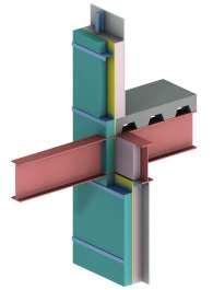
9 Interface Details A Clear Field Assembly A Interface Detail 9

10 Interface Details 10

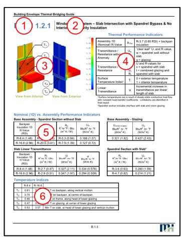
11 Building Envelope Thermal Bridging Guide

12 1365-RP and Beyond Connected the dots Thermal Performance Whole Building Energy Analysis Cost Benefit Analysis Construction Cost Analysis
13 Guides within a Guide Introduction Part 1 Part 2 Part 3 Building Envelope Thermal Analysis (BETA) Guide Energy and Cost Analysis Significance, Insights, and Next Steps Appendix A Material Data Catalogue Appendix B Thermal Data Catalogue Appendix C Energy Modeling Analysis and Results Appendix D Construction Costs Appendix E Cost Benefit Analysis

14 Part 1: Building Envelope Thermal Analysis (BETA) BETA Method Utilization Catalogue Summary Energy Model Inputs

15 Part 1: Building Envelope Thermal Analysis (BETA) Refines ASHRAE 1365 Methodology Step by Step examples Now called the BETA method
16 Beyond parallel path assumptions Assumes heat flows are separate and do not influence each other Averages overall heat flow/resistance based on the areas of components = ( + + ) ( + + ) total 16
17 Why moving beyond this is a good thing Parallel path doesn t tell the whole story Many thermal bridges don t abide by areas There is an easier way to account for details across the board Level playing field will be created when all thermal bridges are thoroughly evaluated 17
 into overall U-values")
18 Part 1: Building Envelope Thermal Analysis (BETA) Part 1 shows how to translate heat flows (clear field, linear and point transmittances) into overall U-values 18
19 Overall Heat Loss Q Q o Qslab Additional heat loss due to the slab

20 Overall Heat Loss Ψ =Qslab/ L linear transmittance represents the additional heat flow because of the slab, but with area set to zero

")

21 Overall U-value (aka Effective R-value) Interface Details Clear Field Assembly
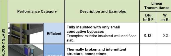
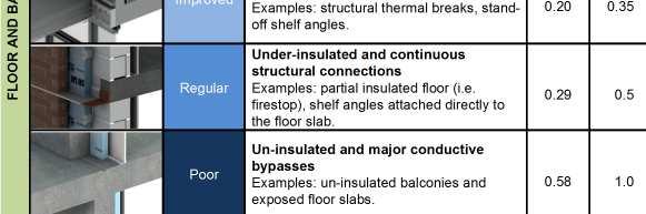
22 Range of Transmittances

23 Appendix A and B

24 Example from the Guide

25 Example from the Guide


26 Part 2 Energy and Cost Analysis Whole Building Energy Use Construction Costs Cost Benefit
27 Part 2 Energy and Cost Analysis

28 Part 2 Energy and Cost Analysis Construction Costs Broad order of magnitude estimates, +-50% Not arrived at for a specific building nor is there a comprehensive list of requirements to base assumptions Construction costs vary quite widely in practice, even with detailed designs

29 Part 2 Energy and Cost Analysis Cost Benefit Analysis The Impact of Interface Details Thermal Bridging Avoidance The Effectiveness of Adding More Insulation Ranking of Opaque Thermal Performance
30 Building Envelope Thermal Bridging Guide (BETB Guide) Insights

31 Building Envelope Thermal Bridging Guide (BETB Guide) NECB 2011 Zone 5 Prescriptive Requirement ASHRAE Zone 5 Prescriptive Requirement ASHRAE 90.1 Calculation BETA Calculation with standard details BETA Calculation with improved details Thermal Transmittance


32 MARKET TRANSFORMATION Vertical Z-Girts Horizontal Z-Girts Mixed Z-Girts Intermittent Z-Girts
33 Origins of Improved Systems

34 Continuous Girts are Now Discrete Systems
35 Interface Details are Significant heat flow associated with details heat flow associated with clear field assembly R-3.8 "Effective" R-9.6 "Effective" 442 R-6.4 "Effective" Wood-frame with R-19 Cavity Insulation Steel-frame with R-10 Exterior and R-12 Cavity Insulation Concrete with R-10 Interior Insulatoin

36 Interface Details are Significant
37 Interface Details are Significant Building Type NECB 2011 Zone 5 U-Value BETA Calculation Value % Incr. U-Value Total Energy Difference ekwh/m² Energy Cost Difference $/m² Commercial Office % 14 $ 0.51 High-Rise MURB % 16 $ 1.39 Hotel % 22 $ 0.64 Large Institutional % 36 $ 1.21 Low-Rise MURB % 14 $ 1.24 Non-Food Retail % 12 $ 0.34 Recreation Centre % 7 $ 0.34 Secondary School % 15 $ 0.53

38 Interface Details are Significant High-Rise MURB with 40% Glazing in Vancouver
39 The Effectiveness of Adding More Insulation Even some expensive options look attractive when compared to the cost effectiveness of adding insulation The cost to upgrade to thermally broken balconies and parapets for the high-rise MURB with 40% glazing may require two to three times the cost of increasing effective wall assembly R-value from R-15.6 to R-20 Seven times more energy savings Better details AND adding insulation translates to the most energy savings and the best payback period


40 Exterior Insulation Finish Systems (EIFS) EIFS with improved details is a 69% improvement in U-value A savings of 14 ekw/m 2 in electricity energy was determined for the high-rise MURB with 40% glazing An example where EIFS is more expensive There is currently no incentive to realize these savings

41 Condensation
42 The Bottom Line More attention needs to be paid to minimizing thermal bridging at interface details for all buildings More energy savings can be realized with improving details than simply adding more insulation Sometimes a small amount of insulation in a gap makes a difference
43 Role and Challenges of the AHJ Move past only checking insulation levels Differences and silence on thermal bridges at interface details has created confusion and enforcement challenges Enforcement requires understanding of the differences between the reference standards
44 Energy Codes and Standards Overview ASHRAE Standard 90.1 NECB 9.36
45 Energy Standards Thermal bridges at transitions is currently not captured Not punished Or rewarded to implement feasible solutions to mitigate thermal bridging at interface details 45
46 Continuous Insulation vs. Insulation Continuity Despite the intent of the continuous insulation concept, to make it simple and not require calculations, this approach does effectively deal with thermal bridging NECB 2011 (and now 9.36) is based exclusively on effective U-values, but has many relaxations for accounting for thermal bridging
47 Envelope Requirements Mandatory requirements Prescriptive requirements ASHRAE NECB 2011 Yes, for all methods Generally less demanding R values Not for energy modeling Stringent, specific Framing Accounted Accounted Structure Not clear Specific Cladding attachments Accounted Service penetrations Ignore Only if repetitive Specific Walls More categories Less categories Fenestration & doors More categories Trade-off methods Complex, no benefit if FDWR <40% Less categories Simple or software Benefit if FDWR <40%


48 ASHRAE 90.1 Overview ASHRAE 2004 Baseline ASHRAE 2007 Increased BE requirements ASHRAE 2010 No major changes in BE requirements
49 ASHARE 90.1 Thermal Bridging Similar to NECB for wall assemblies, but with a lot less clarity Balcony slabs are uninsulated mass walls? Difficult to enforce for other common thermal bridges at interface details continuous insulation (c.i.): insulation that is continuous across all structural memberswithout thermal bridges other than fasteners and service openings. It is installed on the interior or exterioror is integral to any opaque surface of the building envelope.
50 ASHRAE Prescriptive Opaque areas For multiple assemblies within a single class of construction for a single conditioning space, can be combined using a weighed average
51 Above Grade Walls NECB 2011 Above-Grade Walls Any Occupancy Assemblies R values (effective) Zone 4 Zone 5 Zone 6 Zone 7 Zone 8 Walls Roofs Floors Mass 11.4 Metal Building 14.5 Steel-framed 15.6 Wood-framed and other 19.6 ASHRAE Above-Grade Walls Residential
52 Appendix A TABLE A3.3 Assembly U-Factors for Steel-Frame Walls Overall U-Factor for Assembly of Base Wall Plus Continuous Insulation (Uninterrupted by Framing) Rated R-Value of Continuous Insulation = R-8 = R-8 + R-8 52
53 Acceptable calculation methods Construction Classes Testing or Modeling Series calculation method Insulation above deck Parallel path calculation method Isothermal planes method Roofs Attic (wood joists) Attic (steel joists) Mass Walls Steel framed Wood framed 53
54 ASHRAE 90.1 Prescriptive - Fenestration Components Non-Metal Framing 0.35 Metal Framing (curtain wall and storefront) Zone 5 Residential Non-Residential Semi-Heated U factor SHGC U factor SHGC U factor SHGC Metal Framing (entrance doors) for for 1.20 all all Metal Framing (operable and fixed windows, nonentrance doors) for all 54
55 Silence and Ambiguity Leads to an Un-level Playing Field Can a Concrete Balcony and Steel-Frame Wall comply with the Prescriptive Path?

56 ASHRAE 90.1 Trade-off Need to : Do take-offs for all the different BE components i.e. floor, roof, wall and fenestration assemblies forevery space-conditioning category and every orientation. Evaluate the U values of each component including SHGC and VT for fenestration. Enter all the numbers into a series of equations that you can find in normative Appendix C*. * COMcheck(Now has Canadian climate data). Axis Raymond Letkeman Architects 56

57 COMcheck 57
58 ASHRAE Code (ECB) vs. LEED (App G) Section 11: Energy Cost Budget Any envelope assembly that covers less than 5% of the total area of that assembly type (e.g., exterior walls) need not be separately described. If not separately described, the area of an envelope assembly must be added to the area of the adjacent assembly of that same type. Appendix G All uninsulated assemblies (e.g., projecting balconies, perimeter edges of intermediate floor stabs, concrete floor beams over parking garages, roof parapet) shall be separately modeledn. Any other envelope assembly that covers less than 5% of the total area of that assembly type (e.g., exterior walls) need not be separately described provided that it is similar to an assembly being modeled.

59 Silence and Ambiguity Leads to an Un-level Playing Field Appendix G: Slab Edges

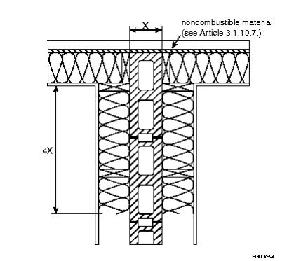
60 NECB (9.36) -Thermal bridging Clear Field Assembly The thermal bridging effect of closely spaced repetitive structural members (e.g. studs) and of ancillary members (e.g. sill and plates) should be taken into account. Floor Slab Interface Detail The thermal bridging of major structural elements that are parallel to the building envelope can be ignored, provided that they do not increase the thermal transmittance to more than twice than permitted. 60
 -Thermal bridging Clear Field Assembly The thermal bridging effect of closely spaced repetitive structural")

61 NECB (9.36) -Thermal bridging Clear Field Assembly The thermal bridging effect of closely spaced repetitive structural members (e.g. studs) and of ancillary members (e.g. sill and plates) should be taken into account. Balconies Interface Detail The thermal bridging of major structural elements that must penetrate the building envelope need not be taken into account, provided that the sum of the areas is less than 2% of the above ground building envelope. 61

62 NECB (9.36) -Thermal bridging Clear Field Assembly The thermal bridging effect of closely spaced repetitive structural members (e.g. studs) and of ancillary members (e.g. sill and plates) should be taken into account. Clear Field and Interface Details?..pipes, ducts, equipment with through-the-wall venting shelf angles, anchors and ties and associated fasteners, and other minor structural members that must completely penetrate the building envelope to perform their intended function need not be taken into account 62
")
63 NECB (9.36) Insulation Continuity 63

64 2012 BCBC - Enforcement 64


65 Vancouver Building by-law 65


66 Energy Codes and Standards Development

67 Reduce the Confusion We no longer need to ignore thermal bridging and apply haphazard exceptions based on assumptions that are no longer valid The BETB Guide provides a straightforward approach supported by a lot of data Straightforward to amend NECB and 9.36, but will require a detailed U-value calculation ASHRAE 90.1 is a little more complicated 67
68 Next Steps Improve the ability to enforce the code and level the playing field by adding clarity Replace exceptions based on wall areas with metrics that represent heat flow like linear transmittance or remove all exceptions Create incentives and reward improved details when practical Use the guide to help policy and authorities implement programs that are more enforceable

69 Challenges Thermal bridging not recognized by the standards has always existed All the compliance paths reference the prescriptive requirements. Thermal bridging has to be carried through for all the compliance paths U-value requirements likely need to be relaxed if accounting for all thermal bridges

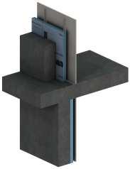
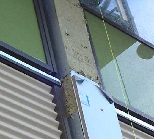
70 Challenges Window transitions are a big deal

71 Challenges Window transitions are a big deal

72 Tools will help the process
73 Conclusion Details such as slab penetration are easy to account for in calculation Codes do not yet take into account details such as window transitions It will likely become increasingly more difficult to ignore thermal bridging at intersections of assemblies Move beyond simply adding more insulation


74 Questions?

75 Thank You