Design and Manufacturing of Modular Wind Turbine Blades
|
|
|
- Valerie Carroll
- 5 years ago
- Views:
Transcription
1 Design and Manufacturing of Modular Wind Turbine Blades Kyle K. Wetzel, Ph.D. Wetzel Engineering, Inc. Austin, Texas USA

2 Wetzel Engineering Engineering Consultancy Clients on 4 continents > 50 custom blade designs; > 16,000 blades operating Engineering services to OEMs, Owners and Operators Hardware design, fabrication, testing, and certification; Forensics engineering and root cause analysis


3 Wetzel Engineering System & Component Optimization Mechanical Design & Testing Mechanical Testing Controls Engineering Dynamics, Loads, & Performance Analyses Aerodynamics: Airfoil Design CFD Wind Tunnel Model Construction & Testing Root Cause Analysis Structural Design & Analysis Structural Testing (including NDE) Manufacturing Process Engineering Tooling Design Manufacturing Support Prototype Manufacturing Tailored Composite Materials Development and Engineering Certification Support
4 Modular Space Frame Blade Acknowledgements -USDOE has provided $1.15 million in support for this project through Phase 1 and 2 SBIR Grants DE-SC Thanks to Jose Zayas, Mike Derby, Mark Higgins, et al. -Entire team at WEI, especially Amool Raina, Ken Lee, Ryan Barnhart, Alex Tran, Alejandra Escalera, Teeyana Wullenschneider, and James Moore

5 Modular Space Frame Blade Three spars connected by ribs Solid Spars No trusses Pultruded Spars Minimal infused fabric Non-structural Skins No core in the shell Major Sections are Factory Assembled Open Assembly Fixtures Ribs & Spars are Bonded Parts are Sized for Transport Major Sections are field assembled

6 Motivation for the Space Frame Engineering of a 100m blade for a 10MW wind turbine in China motivated major changes in the approach to design and manufacturing Elimination of shell panel buckling as a design driver


7 Motivation for the Space Frame Engineering of a 100m blade for a 10MW wind turbine in China motivated major changes in the approach to design and manufacturing Elimination of shell panel buckling as a design driver Reduction in quantity of core in the shell 100m blade would have almost 10,000kg of balsa
8 Motivation for the Space Frame Engineering of a 100m blade for a 10MW wind turbine in China motivated major changes in the approach to design and manufacturing Elimination of shell panel buckling as a design driver Reduction in quantity of core in the shell 100m blade would have almost 10,000kg of balsa Which would also soak around 6,000kg of epoxy Core is Expensive!
9 Motivation for the Space Frame Engineering of a 100m blade for a 10MW wind turbine in China motivated major changes in the approach to design and manufacturing Elimination of huge clamshell molds Elimination of blind bonds that are difficult to control and inspect Lends itself to modularization Borrows for aerospace design

10 Advantages of the Space Frame Substantial reductions in weight and cost Buckling is addressed more efficiently Reductions in capital expenditures Enables cost-effective production of smaller volumes of a given blade design Improvement in Quality Elimination of laminate-related quality problems Elimination of weight tolerance issues associated with infusion of fabric and core Easier inspection of adhesive bonds More fault-tolerant design loads are carried through multiple spars and stringers Reduction in labor more amenable to automation
11 Motivation for Modularization Easier Transportation for land-based machines DOE solicitation related to logistics for large landbased machines WEI project focused on 6MW land-based machines Concepts could benefit blades >50m Easier installation for both land-based and off-shore Versatility in Manufacturing Smaller Plants

12 Motivation for Modularization Versatility in Manufacturing Smaller Fixturing Smaller Parts to Move Smaller Manufacturing Plants Lends itself to either factory or field assembly
13 Development Plan Structural Component Designs Completed Structural Component Tests Completed m Subscale Demonstrator Completed m Subscale Prototype Fabricated m Prototype Test Complete m Detail Design Complete Commercialization of the concept in large blades would likely occur through Joint Ventures with established turbine or blade OEMs

14 Design Study 83m Blade for 6MW (WEI) machine Design Class Class I Parked Class II Operating Class III Fatigue Variable speed, full-span pitch-regulated
15 Cost Benefits 83m, 6MW Conventional Structure Space Frame Structure Total Material Weights (kg) 31,493 Total Labor (Hours) 1,650 23,862 1,350 Total Material $ 292,022 Labor (hours; $/hr) $ 40,425 Total Direct $ 332,447 G&A (20%) $ 66,489 Facilities $ 22,455 Tooling Amortization $ 17,386 Total Indirect $ 106,330 COGS $ 438,777 % Reduction $ $ $ $ $ $ $ $ 221,895 33, ,970 66,489 9,855 8,684 85, , %
16 Cost Benefits 83m, 6MW Transportation Costs Conventional 83m Cannot presently be moved long distances in the US If it could, $115,000-$150,000 to move 1,000 miles % of total installed cost of turbine Modularized into 4 primary sections and 3 smaller sections, $24,000 to move 1,000 miles Modularized further can reduce the cost to $15,000
17 Cost Benefits 83m, 6MW COE Reduction due to Space frame Technology Reduction Cost of Energy Component in COE 7.0% Increased Annual Energy Production from larger rotor enabled by weight reduction 3.0% Extended design life 3.0% Reduced transportation cost 3.0% Reduced materials cost from structural efficiency and more stringent quality control 1.0% Reduced warranty and maintenance costs 17.0% Total Savings
18 Development Plan 34m Prototype Preliminary Design is Complete Parameter Units GE34m Baseline WEI 34m Conventional WEI 35m Conventional WEI 36m Conventional WEI 34m Space Frame AEP MWhr Blade Root knm <3871 Mxy Blade Mass* kg <4400kg
19 Development Plan 34m Prototype Preliminary Design is Complete

20 Development Plan 34m Prototype Preliminary Design is Complete Design refinement is required to resolve buckling issues Shear Web Stress Spar Stress


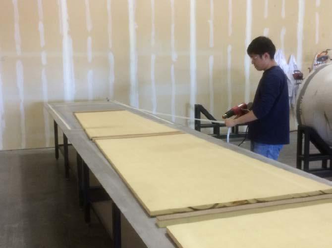
21 Development Plan 10m Demonstrator in Progress Pultruded Spars Composite Ribs Composite Shear Webs
22 ANSYS 15.0 Shell elements for modeling spars & ribs Beam elements for modeling ribs Solid elements for modeling adhesive bonds 10m Test Article Finite Element Modeling Test Loads equivalent to 34m blade Pultruded Spars Composite Ribs Composite Shear Webs

23 10m Test Article Adhesive Bond Results Lap Shear stresses maintained below 3.1MPa
24 Hollow Pultrusions for Spar Caps Patent Pending
25 Hollow Pultrusions for Spar Caps Can a hollow channel be used to improve buckling resistance of a thin carbon spar cap with no increase in mass? Can this be modeled using an equivalent solid channel with adjusted modulus while capturing both deflection & buckling
26 Hollow Pultrusion Design Study The fixed parameters are as follows (based on 65m blade for 3MW turbine): Sparcap Width, w = 600mm Total Sectional Thickness, h= 1006mm Web Thickness, t w = 150mm Bond Thickness, t b = 6mm Web Core Material = PVC Foam Web Face Sheet Material: Double bias (±45 ) fiberglass-reinforced plastic The variables are then confined to: Sparcap thickness, t cap (or t pul ) Sparcap material Pultrusion shape and porosity Flat plates (negligible porosity) Rectangular gaps in laminate stack (variable porosity)
, except that the modulus of the material is altered such that the buckling resistance is equal to that of (2) when the sparcap thickness is remains")
27 Hollow Pultrusion Design Study Conventional Solid laminate with negligible porosity Pultruded Channels Laminate with porosity as defined by the geometry of each pultruded tube Equivalent Conventional Solid laminate with negligible porosity as in (1), except that the modulus of the material is altered such that the buckling resistance is equal to that of (2) when the sparcap thickness is remains constant between (2) and (3), i.e. t cap =t pul. EE 11SSSSSSSSSS = AA pppppp SSSSSSSSS AA ppppppssssssssss EE 11SSSSSSSSS
28 Hollow Pultrusion FEM Model Configuration Step Configuration Material Type Modulus of Carbon, E 11 Sparcap Thickness, t cap Pultrusion Height, t pul t pul,top t pul,bot t web Cross Sectional Area, A tot GPa mm mm mm mm mm mm 2 1 Conventional Prepreg N/A N/A N/A N/A Pultruded Pultruded Tube N/A Equivalent Conventional Pultruded Plate N/A N/A N/A N/A Pultruded Pultruded Tube N/A Pultruded Pultruded Tube N/A Pultruded Pultruded Tube N/A Pultruded Pultruded Tube N/A Pultruded Pultruded Tube N/A Conventional Pultruded Plate N/A N/A N/A N/A Equivalent Conventional Pultruded Plate 87.7 N/A 45.0 N/A N/A N/A Equivalent Conventional Pultruded Plate 99.9 N/A 39.5 N/A N/A N/A Equivalent Conventional Pultruded Plate 85.1 N/A 46.4 N/A N/A N/A Equivalent Conventional Pultruded Plate 61.2 N/A 64.5 N/A N/A N/A Equivalent Conventional Pultruded Plate N/A 35.0 N/A N/A N/A 21000

29 Hollow Pultrusion FEM Model Design ANSYS 15.0 Sparcap elements are 20 node SOLID186 brick elements o Material moduli are dependent on the configuration Adhesive elements are 20 node SOLID186 brick elements Web core elements are 20 node SOLID186 brick elements Web face sheet elements are 8 node SHELL181 elements
30 Hollow Pultrusion FEA Results 1 st Iteration
31 Hollow Pultrusion FEA Results 2 nd Iteration
32 Hollow Pultrusion FEA Results 3 rd Iteration
33 Hollow Pultrusion FEA Results Trends >3X Increase of buckling resistance of the spar cap achieved hollow pultrusion geometry studied Cannot collapse various hollow geometries to a single equivalent solid geometry Cannot simultaneously capture stiffness & buckling with a single set of characteristics
34 Hollow Pultrusion FEA Results Trends >3X Increase of buckling resistance of the spar cap achieved hollow pultrusion geometry studied Cannot collapse various hollow geometries to a single equivalent solid geometry Cannot simultaneously capture stiffness & buckling with a single set of characteristics
35 Conclusions No show-stoppers are identified with respect to achieving the space frame concept Challenge remains resolving buckling in a relatively lightly reinforced structure Solutions have been identified
36 Thank you! Wetzel Engineering, Inc (office) (mobile) 821 Grand Avenue Parkway Pflugerville (Austin), Texas U.S.A.