Seismic Design of Ductile Shear Walls
|
|
|
- Milton Bryan
- 5 years ago
- Views:
Transcription

 2.")
 b) 2014 Design (30) 3.")
 b) 2014 Design (30) 2018")
1 Seismic Design of Ductile Shear Walls 12:30 PM 2:30 PM Bennett Banting Lecture Outline and 2014 Standards Overview (15) 2. Moderately Ductile Squat Shear Walls a) 2004 Design (15) b) 2014 Design (30) 3. Moderately Ductile Shear Walls a) 2004 Design (30) b) 2014 Design (30) 2018 Canada Masonry Design Centre 1


2 2005 NBCC Post-disaster a building that is essential to the provision of services in the event of a disaster 2005 Seismic Exemption Large portions of Canada exempt from seismic design Seismic Hazard Index < Change No exemption Simplified analysis when seismic hazard index less than 0.16 Post-Disaster structures under this threshold need not have R d = Canada Masonry Design Centre 2


 F elastic Expected Strength F")
3 Equivalent Static Procedure Applicable still for most masonry buildings Low rise Low risk areas Regular structures Elastic Force Equal Displacement Assumption Elastic Force 5% Damping Reduced by ductility and over strength factors R d, R o Unreinforced masonry Designed to be elastic R d, R o = 1.0 No ductility (conservatively assumed) F elastic Expected Strength F design R d R o F Δ Δ y Δ u 2018 Canada Masonry Design Centre 3


4 Eliminate Eliminate: Limited Ductility Shear Walls Category CSA S304 Add Add: Ductile Shear Walls Category Add Add: Seismic Chapter 16 Change Change: Variety of Provisions that cover all wall types Challenges with the 2004 Standard Limited Prescriptive Requirements Capacity design principles Stiffness degradation Reinforcement detailing Inelastic curvature capacity calculations Squat Wall Reinforcement 2018 Canada Masonry Design Centre 4

5 Seismic Force Resisting Systems 2005 Seismic Force Resisting Systems Canada Masonry Design Centre 5

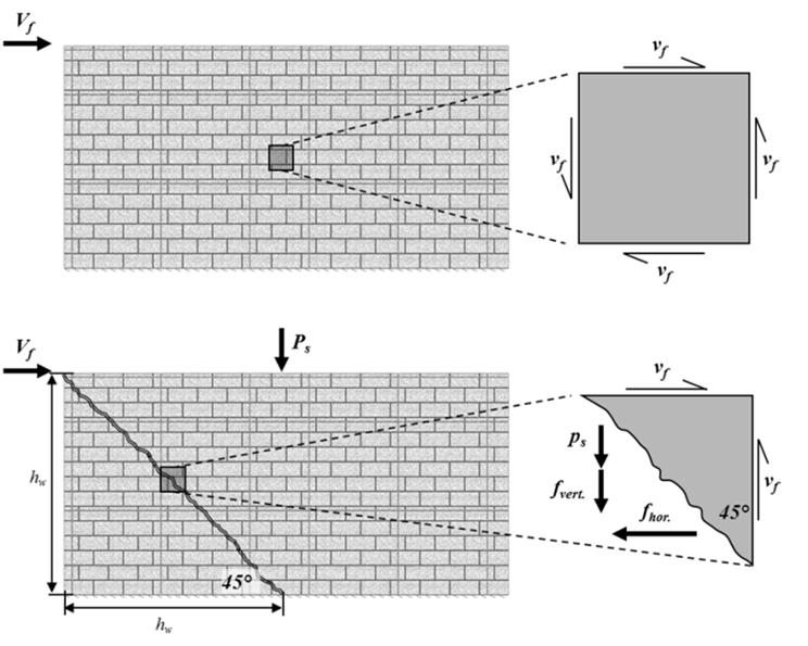
6 Moderately Ductile Squat Shear Walls (Pages ) Cl CSA S304 General Provisions Canada Masonry Design Centre 6


 < 20 Reinforcement Ratios ϕ")

7 Unsupported Heightto-Thickness Ratio Ductility Reversed cycles of displacement Yielding in tension compression Propensity for buckling Single layer of reinforcement h/(t+10) < 20 Reinforcement Ratios ϕ s ρ v Vf Pf b w l w f y P f ϕ s ρ h ϕ s ρ v b w l w f y 2018 Canada Masonry Design Centre 7

8 2014 CSA S304 Reinforcement Ratios 2018 Canada Masonry Design Centre 8
9 Reinforcement Ratios P s ρ v ρh ϕ s b w l w f y V f ρ h ϕ s b w h w f y Flexure- Governed and Shear- Governed Walls Minimum level of ductility assured No feasible means to evaluate precise shear ductility 2 Pathways Flexural Failure Must increase shear resistance to ensure flexural failure Shear Failure No additional shear resistance if shear governed 2018 Canada Masonry Design Centre 9


10 Shear Governed Wall h w = 3,000 mm l w = 3,200 mm D L = 150kN +S.W., E L = 50kN, L L = 50kN, S L = 75kN M f = 150 knm V f = 50 kn Partially-Grouted Construction 20cm Concrete Block Units 25MPa Specified Block Strength Vertical Reinforcement = 1,200mm Horizontal Reinforcement = 1,200mm Flexural Governed Wall h w = 3,000 mm l w = 3,200 mm D L = 150kN +S.W., E L = 50kN, L L = 50kN, S L = 75kN M f = 150 knm V f = 50 kn Fully-Grouted Construction 20cm Concrete Block Units 25MPa Specified Block Strength Vertical Reinforcement = 1,200mm Horizontal Reinforcement = 1,200mm 2018 Canada Masonry Design Centre 10

11 Reinforcement Detailing Where reinforcing bars are used 90 Standard Hook No lapping of horizontal reinforcement within 600 mm or l w /5 of wall ends Review Moderately Ductile Squat Shear Walls A standard wall type for low-rise structures 2004 design requirements made it difficult to detail Unintentional consequence 2014 CSA S304 Better clarification on reinforcement ratios Capacity design Specific end anchorage conditions for horizontal reinforcement 2018 Canada Masonry Design Centre 11
 Cl. 10.")

12 Moderately Ductile Shear Walls (Pages ) Cl CSA S304 General Provisions Canada Masonry Design Centre 12
 of Plastic Hinge 1. Academic 2. Analysis for Capacity 3.")
13 Plastic Hinge Visualized by Curvature ϕ y M r h p M y ϕ u E m I cr M cr E m I o ϕ y ϕ u Plastic Hinging Concentration of inelastic rotations Facilitates ductility Extent(s) of Plastic Hinge 1. Academic 2. Analysis for Capacity 3. Prescriptive Detailing 2018 Canada Masonry Design Centre 13

14 Plastic Hinge Region Extent greater of l w or h w /6 Supported h/(t + 10) < cm = 2.8 m 25 cm = 3.5 m 30 cm = 4.2 m ε mu = h w / l w < 4 c < 0.2lw 4 h w / l w < 8 c < 0.15lw Plastic Hinge Region Clause Applies as well Generally Cl is more restrictive One key requirement is missing in CL Canada Masonry Design Centre 14
15 Ductility Verification Ductility Ratio of inelastic deformations to elastic deformations Types Curvature Rotation Displacement μ ϕ ϕ u ϕ y μ θ θ u θ y μ u y Elastic Beam Theory θ ϕ h 3 ϕ oh w 2 ϕ ϕ 1 u h 2018 Canada Masonry Design Centre 15

16 Elastic Limit Elastic definition Reinforcement up to yield Masonry linear elastic region Define Yield Curvature ϕ y ε s = ε y ϕ h 3 Plastic Hinge Theory V Δ y Δ y + Δ p = Δ u Elastic Deformation until yielding Yielding extends up from base Development of bars Tension shift from shear cracks Penetration of yield strains into footing Plastic hinge Top of wall rotates about centre of hinge y ϕ u ϕy h p h w h p Canada Masonry Design Centre 16


17 Plastic Limit Ultimate Limit States Masonry crushing failure Reinforcement past yield Ultimate Curvature ϕ u ε mu = now Rotation Concentrated in Plastic Hinge Elastic curvatures elsewhere above From Previous Lecture M f = 1,600 knm P f = 550 kn 6.0 m Long h p = 6.0m 8.0 m Tall 25 cm Units 30 MPa Block, Type S Mortar, Fully-Grouted 20M Vertical m Determine ϕ y, ϕ u, μ Δ 2018 Canada Masonry Design Centre 17
 Extreme tension reinforcement yielding b) Elastic stress-strain in masonry c)")

18 Determine Yield Curvature 1. Strain Compatibility a) Extreme tension reinforcement yielding b) Elastic stress-strain in masonry c) Compression reinforcement considered d) No material reduction factors ϕ ε d c Determine Yield Displacement 2. Force Equilibrium a) Elastic stresses in reinforcement b) Elastic stress is masonry c = 1,189.2 mm F s ε s E s A s C ε m E m bc 2 ϕ y ε y d 1 c 2018 Canada Masonry Design Centre 18

19 Determine Ultimate Curvature Strain Compatibility Possible iterative solution with multiple bars yielding or not yielding Set ε mu = No material reduction factors Consider compression stress in reinforcement Force Equilibrium c = mm ϕ u c Shear Resistance Reduce shear capacity within plastic hinge Masonry + Axial Load reduce by 50% Reduced sliding shear capacity at base of wall Reversed cycles of loading Reduce C by compressive force in reinforcement 2018 Canada Masonry Design Centre 19

20 Reinforcement Requirements Major Changes Unsupported Height Limits of Plastic Hinge Partial Grouting of Plastic Hinge Horizontal Reinforcement Requirements Lap Splices Extent of Plastic Hinge Ductility Verification Shear Capacity in Plastic Hinge 2014 CSA S Canada Masonry Design Centre 20
 < 20")


21 Unsupported Wall Height Plastic Hinge Region h/(t + 10) < 20 Unless h/(t +10) < 30 Flange Boundary Element Limited compression zone c < 4b w or 0.3l w Partially- Grouted Plastic Hinge Low Aspect Ratio Low seismic hazard index 2018 Canada Masonry Design Centre 21


22 Reinforcement Details 90 Hooks when reinforcing bars are used in horizontal reinforcement No restriction on amount of vertical reinforcement lapped at any one cross-section Lap splices increased to 1.5l d Inelastic Rotational Demand 2018 Canada Masonry Design Centre 22


23 Inelastic Rotational Demand Explicit validation of rotational ductility Top displacements estimated from crack section properties Consider whole building effects on rotations Plastic hinge Centre of rotation (denominator) h p = l w l ϕ h 3 θ ϕ oh w 2 ϕ ϕ 1 u h Inelastic Rotational Demand ϕ ε d c l 2 In the Plastic Hinge θ ϕ h p ϕ l θ ϕ h p l Canada Masonry Design Centre 23


24 Inelastic Rotational Capacity Plastic Hinge capacity is based on conservatively small plastic hinge l / 2 Plastic Hinge demand is based on a conservatively large plastic hinge l w θ l From Previous Lecture M f = 1,600 knm P f = 550 kn 6.0 m Long 8.0 m Tall Vh Vh f1 3EI 0.4EA I g tl 12 Δ f1 = 2.19 mm θ R R γ h l A g tl w θ ε l w c 2018 Canada Masonry Design Centre 24


25 Shear Strength Shear Design Strength Flexural ductility reduces shear strength Masonry and Axial Load Component multiplied by 75% Shear Design Force Capacity design principles to assure flexural failure Shear to meet that equal to lesser of nominal moment capacity R d R o = 1.3 Building Effects Plastic hinge and displacement based on longest wall Acknowledges rigid diaphragm effects Top displacement equal Not rotations or ductility demand 2018 Canada Masonry Design Centre 25
26 Building Effects Multiple Walls Multiple ductilities Earthquake force reduced by single RdRo Attempt to reconcile this with longest wall Review Moderately Ductile Shear Walls (2004) Cumbersome to design Lack of prescriptive details Very restrictive reflecting state of research Moderately Ductile Shear Walls (2014) Updated and more advanced Reflective of CSA A23.3 and masonry research Should help with post-disaster structures 2018 Canada Masonry Design Centre 26