THERMAL BRIDGING OF MASONRY VENEER CLADDINGS & ENERGY CODE COMPLIANCE
|
|
|
- Austin Blair
- 5 years ago
- Views:
Transcription

1 12 th Canadian Masonry Symposium Vancouver, British Columbia, June 2-5, 2013 THERMAL BRIDGING OF MASONRY VENEER CLADDINGS & ENERGY CODE COMPLIANCE Graham Finch MASc PEng, Michael Wilson MEng PEng, & James Higgins Dipl.T, RDH Building Engineering Ltd. Vancouver, BC, Canada ABSTRACT Current industry standards for overall building energy efficiency have resulted in a significant trend towards the placement of exterior semi-rigid or rigid insulation within the exterior air space behind exterior masonry veneers. Compliance with new energy standards brings attention to the impact of thermal bridging caused by masonry connectors that penetrate this exterior insulation. The need to address thermal bridging to achieve compliance with either the National Energy Code for Buildings (NECB) or ASHRAE Standard 90.1 is examined in the context of masonry connector design and selection. This paper presents the results of three dimensional thermal modelling which quantifies the actual impact of thermal bridging in typical exterior masonry veneer wall assemblies. Results for multiple masonry connector types including ties and shelfangles are presented. Additional variables in the analysis include material types such as stainless steel and basalt fiber, varying levels of insulation within the wall assembly and backup wall type construction. The results demonstrate that the impact of masonry ties on thermal performance is important and can be very significant in many situations. The results of a comparative study are also presented to illustrate the impact of thermal bridging caused by comparable non-masonry cladding assemblies supported by continuous/intermittent metal Z-girts, clips or screws. The information presented in this paper is of interest to design professionals responsible for assessing overall building energy efficiency and code compliance and therefore the need to address masonry connector thermal bridging. INTRODUCTION National, Provincial and Municipal building codes in Canada have for some time referenced either ASHRAE Standard 90.1 or the National Energy Code for Buildings (NECB, previously MNECB) for the energy efficiency requirements for buildings. Both of these energy standards have been recently updated (2011 NECB and 2010 ASHRAE 90.1) and more stringent thermal requirements for walls (i.e. minimum R-values) have been adopted. Minimum R-values in 2011 NECB and ASHRAE 90.1 require that thermal bridging through the exterior insulation be accounted for. This means that structural framing including the studs, girts, slab edges etc. need to be considered in thermal calculations. In some jurisdictions, Energy Codes may be interpreted to allow for some analysis simplifications to reduce the burden on designers to account for thermal bridging in enclosure assemblies. One such simplification is the allowance is for the designer to ignore the area of a thermal bridge if its area occupies less than 1% (or in some cases up to 5%) of the wall surface area for energy code compliance calculations. This means that small clips including masonry ties and shelf angles may be ignored in some energy code compliance checks. This may not seem
2 that significant, however as will be demonstrated in this paper, metal cladding support connections occupying less than 0.5% and even less than 0.05% of the walls surface area can have a profound impact on effective R-values (i.e. in order anywhere from 10% to greater than 50%). This paper presents typical exterior insulation reduction factors and effective R-values to support these values for masonry walls with various tie types applied to concrete, steel stud frame, and wood-stud frame backup walls. The influence of the masonry support shelf angle is also presented. Finally the effective R-values and percentage effectiveness of exterior insulation for masonry veneer walls are compared to other common cladding support systems including horizontal and vertical Z-girts and intermittent clips. BACKGROUND & ENERGY CODE REQUIREMENTS FOR WALLS IN CANADA Awareness and understanding of the building code, related standards, and the various energy compliance paths is required in order to establish the context for thermal considerations and masonry veneer support systems. In Canada there are two national model codes that specify energy efficiency provisions for buildings: the National Building Code of Canada (NBC) and the National Energy Code for Buildings (NECB), which was previously called the Model National Energy Code for Buildings (MNECB). These National Codes are adopted either with or without modifications by each of the Provinces and Territories. The City of Vancouver, BC has a modified version of the BC Building Code written into their municipal building bylaws. The NBC thermal performance requirements for the building enclosure are provided for single family housing and low-rise buildings (Part 9 buildings). The thermal performance requirements for larger (Part 3) buildings are provided by the NECB. The Province of BC has adopted ASHRAE and Ontario has adopted a combination of ASHRAE and 2004 for large building energy code compliance. The City of Vancouver through its Building Bylaw has adopted ASHRAE Both the Province of BC and City of Vancouver are in the public review process for the adoption of ASHRAE (plus NECB 2011). The 1997 MNECB building enclosure performance requirements are often used in LEED energy simulations and the new 2011 NECB is currently undergoing review for adoption into many of the provinces. Compliance with the building enclosure provisions of ASHRAE Standard 90.1 requires meeting some prescriptive and mandatory requirements as well as one of the three alternate building enclosure compliance paths. The three compliance paths include, in order of lowest to highest complexity and level of work required to demonstrate building project compliance: Prescriptive Building Envelope (Enclosure) Option, Building Envelope (Enclosure) Trade-off Option, or Energy Cost Budget Method. In all of these compliance paths, the effective R-value of each building enclosure assembly needs to be determined. Nominal insulation R-values are the rated R-value of the insulation product being installed and do not account for losses due to thermal bridging. Thermal bridging is the energy loss that occurs through framing, gaps, fasteners, structural elements, and any other penetrations through the installed insulation. Historically, most building codes have specified nominal insulation R-values in order to simplify the requirements for builders and designers of small buildings (i.e. Part 9).
3 The effective assembly R-values that could be constructed using the nominal insulation value would of course vary depending on the type of framing and degree of thermal bridging, thereby resulting in a significant range of actual thermal performance. Therefore, the use of effective R- values is a more rational measure of the true thermal performance. The use of effective R-values rather than nominal R-values in building and energy codes is also becoming more common because two and three-dimensional finite element heat flow calculation software is readily available and used by practitioners to calculate effective R-values. Building and Energy Codes and Standards that use effective and nominal R-values compliance paths include: ASHRAE 90.1 (all versions), 2011 National Energy Code for Buildings (NECB) in Canada, and the 2010 National Building Code of Canada (NBC). Most Provincial building codes adopting the 2010 NBC (and 2012 Part 9.36 energy efficiency updates will also be adopting the use of effective R-values. Guidance is provided within these codes and standards regarding how to calculate the effective R-values of common enclosure assemblies. The use of nominal insulation R-values for building enclosure code compliance is still permitted in most current versions of Provincial and National Building Codes in Canada for Part 9 buildings (houses and smaller wood-frame MURBs). While nominal insulation R-values may be referenced within codes, there is some understanding of the most common assemblies that will be built (i.e. batt insulation of certain R-value between wood or steel studs) and hence the need for continuous insulation requirements for some assemblies to ensure a minimum effective insulation level (effective R-value). Continuous Insulation (ci) is a definition used with ASHRAE 90.1 and other Energy Codes and standards with the intended purpose of providing at least a minimum continuous layer of insulation that has an effective R-value equal to or very close to equal to its nominal R-value (i.e. no or minimal thermal bridging). Continuous insulation is often specified in energy codes alone or in conjunction with thermally bridged nominal insulation (i.e. between wood studs) to achieve higher effective R-values. This ci requirement is commonly addressed with exterior rigid or semi-rigid insulation installed on the exterior of a framed assembly. Continuous insulation could also be installed to the interior or within the middle of some assemblies, although it would not meet the requirement for continuity at floor levels in multi-storey buildings. Figure 1 summarizes the thermal insulation requirements within the 2011 NECB and ASHRAE for walls of all types in climate zones across Canada.
 Minimum Effective Assembly R-value [RSI] ASHRAE 90.")
![1-2010 Above Grade Walls Residential Building (Mass Concrete, Wood- Frame, Steel-Frame) Minimum Effective Assembly R-values [RSI] 18.0 [3.17] (9.6, 11.2, 15.6) [1.69, 1.97, 2.75] 20.4 [3.59] (11.](/docs-images/87/96483416/images/4-1.jpg "1, 15.6, 15.6) [1.95, 2.75, 2.75] 23.0 [4.05] (12.5, 19.6, 15.6) [2.20, 3.45, 2.75] 27.0 [4.76] (14.1, 19.6, 15.6) [2.48, 3.45, 2.75] 27.0 [4.76] (14.1, 19.6, 15.6) [2.48, 3.45, 2.75] 31.0 [5.46] (14.")
4 Climate Zone By Zone and HDD( C) Zone 4 - <3000 HDD Zone HDD Zone HDD Zone 7a HDD Zone 7b HDD Zone 8 - >7000 HDD NECB Above Grade Walls (All Construction Types) Minimum Effective Assembly R-value [RSI] ASHRAE Above Grade Walls Residential Building (Mass Concrete, Wood- Frame, Steel-Frame) Minimum Effective Assembly R-values [RSI] 18.0 [3.17] (9.6, 11.2, 15.6) [1.69, 1.97, 2.75] 20.4 [3.59] (11.1, 15.6, 15.6) [1.95, 2.75, 2.75] 23.0 [4.05] (12.5, 19.6, 15.6) [2.20, 3.45, 2.75] 27.0 [4.76] (14.1, 19.6, 15.6) [2.48, 3.45, 2.75] 27.0 [4.76] (14.1, 19.6, 15.6) [2.48, 3.45, 2.75] 31.0 [5.46] (14.1, 27.8, 15.6) [2.48, 3.45, 2.75] Figure 1: Minimum Effective R-Value Requirements for Building Enclosure Assemblies within 2011 NECB and ASHRAE in Canadian NECB and ASHRAE 90.1 Climate Zones (Note that ASHRAE 90.1 includes Climate Zone 4, Lower Mainland and Victoria, BC with Climate Zone 5 in Canada) Note that where these minimum R-values cannot be prescriptively met, one of the two alternate trade-off paths (Building Enclosure or Whole Building) must be followed. In these paths, higher performing components such as windows or roofs can be used to offset the heat loss at walls which do not meet these criteria. This is particularly relevant for those following the 2011 NECB requirements in colder climate zones (i.e. where R-23 to R-27 (RSI 4.05 to 4.76) effective is required). Note that traditional masonry veneer over an insulated backup wall is not considered in ASHRAE to be a mass wall as the insulation is inboard of the masonry and the mass is not able to influence the heated environment. Uninsulated heavy masonry is considered a mass wall, however it is no longer a common construction method. For comparison, walls within highly insulated net-zero and Passivhaus type buildings would generally have effective R- values in the range of R-40 to R-50 (RSI 7.0 to 8.8) depending on building type, climate zone and other factors. THERMAL ANALYSIS & DISCUSSION A three-dimensional thermal analysis of various masonry tie and alternate cladding support techniques was performed using HEAT3 ( The HEAT3 software package has been well tested and validated by the building industry and is commonly used by practitioners to calculate effective R-values for enclosure assemblies (more so in Europe than North America due to more stringent European Energy code requirements and Passivhaus type energy efficiency programs). Three-dimensional thermal modeling allows for more accurate representation of discrete cladding attachment elements such as brick ties than two-dimensional software. The purpose of the analysis is to provide data on the effective R-values of several masonry tie options, assess the thermal impact of alternate shelf angle configurations, and compare the thermal performance of masonry systems to other claddings. In our experience the R-values calculated from HEAT 3 tend to be conservative due to the way that surface film resistances are
 depending on the back-up wall and")
5 included in the model. Results from guarded hot-box testing and other three-dimensional finite element thermal modeling software packages may be more optimistic (by up to 5% to 10%) depending on the back-up wall and assumed material contact resistances. When accounting for real-life construction practices (e.g. air/insulation gaps around ties, extra ties and fasteners etc.) the conservative results from HEAT 3 tend to be more realistic in our view. MASONRY TIES A series of thermal models were developed to assess the thermal bridging impact of different masonry ties through exterior insulation and different backup wall types. Three different back-up wall types including: 6 concrete, 3-5/8 steel studs (uninsulated), and 2x4 wood studs (insulated with R-12 batts) were modeled with varying levels of exterior insulation and the following different masonry ties options. Galvanized Steel 2 inch x 16 gauge L-brick ties (with and without punched holes to reduce steel area and conductivity in tie) Stainless Steel 2 inch x 16 gauge L-brick ties (with and without punched holes to reduce steel area and conductivity in tie) Stainless Steel 2 inch x 16 gauge brick tie side mounted to stud (for steel and wood stud cases only) Standard 2 inch 16 gauge L-brick tie (no punched holes) Basalt Fiber masonry cavity tie (proprietary UK product for concrete backup wall case only) Figure 2, 3, and 4 respectively present the effective R-values and percentage thermal reduction for the exterior insulation for the different ties on the three backup wall assemblies: 6 concrete, empty 3-5/8 steel studs, and R-12 insulated 2x4 wood studs. The effective R-values for the centre of wall away from slab edge or masonry shelf angle demonstrate only the impact of the masonry tie itself (16 inch horizontal by 24 inch vertical spacing). This works out to the surface area of wall being occupied by the masonry ties at an almost negligible 0.04% (16 gauge x 2 inches at 24 inch by 16 inch standard spacing). A range of exterior insulation R-values have been considered from 0 to 6 inches in nominal R- 4/inch increments (i.e. from R-0 to R-24 (RSI 0 to RSI 4.23)). The results for each masonry tie type are consistent, with slight variations in the absolute R-values and percentage reductions due to the different back-up wall configurations. The back-up wall affects the thermal transfer through the brick ties due to the contact resistance of the connections, with concrete being the worst, followed by steel stud/gypsum, and wood. To convert from IP R-values to metric RSI values, divide values in chart by a factor of


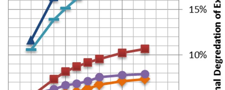
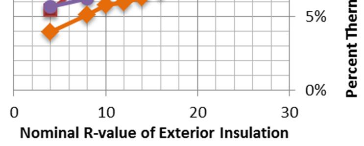
6 Figure 2: Effective R-value of Masonry Walls with Different Masonry Ties 6 Concrete Wall Backup Figure 3: Effective R-value of Masonry Walls with Different Masonry Ties Empty 3 5/8 Steel Stud Wall Backup
7 Figure 4: Effective R-value of Masonry Walls with Different Masonry Ties 2x4 Wood Stud (w/ R-12 batts) Backup The selection of masonry tie material and tie design can have a significant impact on the effective R-value of masonry veneer walls; the effective reduction can be anywhere from 5% to almost 30% depending on the thickness of exterior insulation and back-up wall structure, which can be an important consideration for energy code compliance. Each of these masonry ties occupies 0.04% of the overall wall area, and the rules within some energy codes would allow such thermal bridge effects to be ignored in some energy code compliance checks for simplification purposes. The results here demonstrate that this code compliance simplification results in overstated R-values (by up to 30%) and should not be applied in energy models or for the design of HVAC systems. In terms of masonry tie selection, stainless steel performs significantly better than galvanized steel, with exterior insulation reductions in the order of 5% to 12% for stainless steel over concrete/steel backup versus 15% to 28% for galvanized steel. These insulation reductions are less in wood-framing, in the 5% to 9% range for stainless ties and 10% to 18% for galvanized ties. There are obvious cost implications to these choices; however, the additional cost for stainless ties could be offset by the additional insulation thickness that might be required to meet a certain R-value target with galvanized ties. For the concrete backup wall, the basalt fiber tie has exterior insulation R-value reductions of less than 1% due to the non-conductive nature of basalt fiber, and demonstrates the potential for this type of technology to further improve the thermal performance of masonry walls. This would also be similar to carbon fiber or glass fiber (fibreglass) products also available on the market.

8 MASONRY SHELF ANGLES Masonry shelf angles structurally support masonry veneers and they are typically placed at openings (i.e. over windows and doors) and at the slab edge of every floor. Although shelf angles are not necessarily required at every floor, this typical design practice does accommodate ease of construction, alignment and tolerance requirements. In addition to structural implications, the placement and design of masonry shelf angles also impacts overall thermal performance of the cladding. Traditionally in multi-storey buildings, masonry shelf angles have been directly attached to the concrete slab edge, either welded to embed plates cast in to the slab edge or bolted with adhesive/expansion anchors. This does not have a significant impact on the thermal performance of wall assemblies with stud cavity insulation, or insulation placed to the interior of the backup wall (i.e. discontinuous insulation), however these wall assemblies will likely fail to meet most current energy code requirements. Where exterior insulation is included and where the bottom leg of the shelf angle cuts through the exterior insulation, the shelf angles has a significant impact on the overall thermal performance Standard slab attached shelf angle of the whole wall area. In terms of an area of wall, a steel plate of up to ½ thick steel might represent less than 0.5% of the surface area of the insulation, but can result an effective thermal degradation of the insulation in the order of 30% to 50%+. Current energy codes may even be interpreted to permit the thermal bridging impact of a shelf angle to be ignored on the basis of limited wall area. The analysis presented here demonstrates the importance of rigour in energy analysis and calculations and confirms that solutions exist to reduce the actual large thermal bridge to one that is more manageable, but still accountable for a 15% reduction in actual R-value. A companion paper at this conference by Wilson, Finch, and Higgins (2013) has been prepared which specifically discusses thermal bridging issues of shelf angles in greater detail. A summary is provided here to demonstrate specifically the thermal bridging effect of direct installed continuous shelf angles compared to thermally improved support strategies (i.e. smaller shelf angles exterior of the insulation intermittently supported by knife plates, proprietary brackets, HSS tubes or L-angles), and why shelf angle details need to be considered. Intermittent shelf angle support A thermal analysis is performed to assess the impact of continuous and de-bridged knife plate supported masonry shelf angles. As Wilson, Finch and Higgins (2013) demonstrate, the use of thermally de-bridged intermittent knife plates, HSS tubes, double L-angles, or other proprietary brackets to support shelf angles outside of the exterior insulation, all have a similar reduction factor of the exterior insulation R-value by 15% to 17% (for 4 inches or R-16 of exterior insulation). Figure 5 presents the results of the analysis, which compares the effective R-value of a masonry wall with ties (both stainless and galvanized
9 steel area compared) and with and without the influence of the shelf angle (both direct attached and thermally de-bridged). Figure 5: Effective R-value of Masonry Walls with alternate shelf angle supports and brick tie combinations The thermal impact of masonry shelf angles at every floor can have a profound effect on the thermal efficiency of the wall assembly in addition to the previously shown impact of the masonry ties (solid 16 gauge stainless and galvanized ties area shown here for demonstration). Direct attached masonry shelf angles perform quite poorly from a thermal standpoint with exterior insulation R-value reductions in the order of 40% to 55% for typical exterior insulation thicknesses and stainless or galvanized ties. Depreciating returns for additional exterior insulation mean that it is almost impossible to attain R-values of greater than R-15 (RSI 2.64) in this scenario. Shelf angles supported outside of the exterior insulation with intermittent knife plate or tube shelf angle supports with stainless or galvanized ties have more manageable insulation reductions in the order of 12% to 22%. Effective R-values for wall assemblies with these details are in the R-15 to R-20 (RSI 2.64 to 3.52) range for 3 to 6 inches of exterior insulation. This means that in order to comply with current prescriptive energy code requirements in Canada, generally in the R-15 to R-20 (RSI 2.64 to 3.52) or higher range, the use of intermittently supported and thermally improved shelf angles are necessary. COMPARISON OF MASONRY TO OTHER CLADDING SYSTEMS A final analysis is performed to compare masonry veneer to other cladding systems supported through exterior insulation. Claddings such as metal panel, fiber cement panels, stucco, thin
10 cultured stone, and thin brick etc. with exterior insulation are typically supported by systems including continuous girts, intermittent clips, screws and other systems. These structural elements penetrate the exterior insulation and are typically larger in size than masonry ties and designed to carry gravity and live loads from the claddings. Historically the use of continuous metal Z-girts was most common in construction in Canada, however in recent years the use of more thermally efficient systems has evolved. Figure 4 presents four masonry veneer support conditions ranging from just stainless steel ties to cases which include three different shelf angle/slab support conditions over empty steel stud cavity back-up wall. These are compared to exterior insulated walls with continuous Z-girts (horizontal and vertical 18 gauge), intermittent 6 inch long 18 gauge clips, and intermittent 4 inch long non-conductive fiberglass shear block type spacers with long screws through the insulation. The backup wall assembly for this analysis is an empty 3-5/8 steel stud wall with gypsum sheathing and gypsum interior finish. The results for concrete and concrete block wall backup would be similar and for wood-frame are slightly improved as previously shown. Figure 4: Effective R-value Typical Masonry and Other Cladding Support Strategies of empty 3 5/8 Steel studs As demonstrated by this comparative analysis of other cladding support systems, masonry veneers have the potential to be one of the most thermally efficient cladding systems, provided they are detailed properly. When compared to other claddings, thinner amounts of insulation can be used to achieve the same effective R-value resulting in material and space cost savings and wall thickness reductions. This is important for masonry veneers which tend to be thicker than other claddings to begin with. The results also demonstrate that where effective R-value targets are in the R-15 to R-20 (RSI 2.64 to 3.52) range, this can be achieved with 3 to 4 inches of exterior insulation, whereas many other systems require considerable more insulation to do so, or cannot practically meet the requirements due to the amount of thermal bridging.
11 Thermal bridging through the masonry ties can be reduced to less than 10% through the use of efficient stainless steel ties (even lower using non-conductive basalt or carbon fiber). With the use of de-bridged shelf angle supports, exterior insulation reductions in the order of 16% to 20% (combined shelf angle and ties) are expected. This is significantly better than the reductions of 50% to 80% which can be seen with continuous Z-girts. Even some of the thermally optimized gravity/live load cladding attachment strategies have greater insulation reductions (i.e. greater than 20%) than masonry veneers. This all supports that fact that masonry can be one of the most thermally efficient wall claddings. CONCLUSION The effective R-values of several different masonry ties over different back-up wall construction (concrete, steel stud/gypsum, and wood-frame) were modeled using a three-dimensional finite element computer software program. The results show that the selection of tie material and tie design can have a significant impact on the effective R-value of masonry walls and exterior insulation reductions from 5% to almost 30% can be expected. The use of stainless steel brick ties with punched holes/slots result in the lowest insulation reductions (5% to 12%) compared to galvanized steel (15% to 28%) over concrete/steel stud backup and lower for wood frame. Low conductivity ties including basalt fiber or carbon fiber have the potential to have exterior insulation reductions less than 1% (negligible effect) though are currently limited in use in Canada at this time. The thermal impact of the design of masonry veneer shelf angles was also shown to be very important. Direct attached masonry shelf angles perform quite poorly from a thermal standpoint with exterior insulation R-value reductions in the order of 40% to 55% for typical exterior insulation thicknesses and stainless or galvanized ties. Shelf angles supported outside of the exterior insulation with intermittent knife plate or tube shelf angle supports with stainless or galvanized ties have more tolerable insulation reductions in the order of 12% to 22%. For masonry veneer walls effective R-values in the range of R-15 to R-20 (RSI 2.64 to 3.52) range can be achieved with 3 to 6 inches of exterior insulation depending on masonry tie selection provided that shelf angles are intermittently supported. This generally means that in order to comply with the current and future prescriptive energy code requirements in Canada, the use of intermittently supported and thermally improved shelf angles are necessary. There are potential cost implications to these recommendations towards the use of stainless steel brick ties and intermittently supported (but smaller) shelf angles. These costs can in many cases be offset by the additional insulation thickness that might be required to meet a certain R-value target for energy code compliance or energy consumption target. It is shown that masonry veneer claddings have the potential to perform very well from a thermal standpoint, and will outperform many other exterior insulated cladding assemblies. Typical exterior insulation R-value reductions for well-designed masonry walls will be in the order of up to 20%, whereas continuous girt systems will have reductions in the 50% to 80% range. Even thermally improved cladding support systems have difficulty in achieving exterior insulation R- value reductions lower than 20% due to the larger and more frequent connections required for gravity/live loads. This means that less exterior insulation can be used and thinner masonry walls
12 can be constructed to achieve the same performance as other less thermally efficiently supported claddings. The thermal efficiency and durability of exterior insulated masonry veneer wall assemblies has always been well recognised by the industry; and as this paper demonstrates the recent need to properly evaluate and address thermal bridging is not a detracting requirement for masonry veneer. REFERENCES 1. ASHRAE ASHRAE Standard 90.1 Energy Standard for Buildings except Low-Rise Residential Buildings. Atlanta, Georgia, USA. 2. Blocon. HEAT3. Computer Software National Research Council of Canada National Energy Code of Canada for Buildings (NECB). Ottawa, Ontario, Canada. 4. Wilson, M., Finch, G., Higgins, J Masonry Design Support Details: Thermal Bridging. Proceedings from 12 th Canadian Masonry Symposium, Vancouver, BC, Canada, June 2-5.