IECC Provisions for Multi-Family Buildings
|
|
|
- Maud Powers
- 5 years ago
- Views:
Transcription


1 IECC Provisions for Multi-Family Buildings Both Commercial and Residential Energy Code Requirements Colorado Code Consulting, LLC For SWEEP, 2015
 as well as R-2, R-3 and R-4 buildings three stories or less in height above grade plane.")
2 Residential VS Commercial Definition of Residential per IECC is different than that found in the IRC and IBC: RESIDENTIAL BUILDING. For this code, includes detached one and two family dwellings and multiple single family dwellings (townhouses) as well as R-2, R-3 and R-4 buildings three stories or less in height above grade plane. How is the code used in this building? COMMERCIAL BUILDING. For this code, all buildings that are not included in the definition of "Residential buildings." 2
3 Construction Documentation R103 Submitted details must be able to show full compliance with each code requirement including: Insulation types, locations and R-Values Fenestration types, locations and U-Factors/SHGC Mechanical and water heating size, type and efficiency Equipment and system controls Duct sealing and insulation locations Air sealing details DEPICTION OF THE THERMAL ENVELOPE (R ) R103.3: Code Official can hire someone else to do plan review as long as they were/are not affiliated with the design or construction of the building.


4 New in the Building Thermal Envelope depiction: The buildings thermal envelope shall be represented on the construction documents Example: Blue Exterior air barrier Yellow Thermal Barrier Red Interior air barrier
5 IECC Commercial Compliance Options 1 ASHRAE IECC - Prescriptive C402 - Envelope C403 - Mechanical C404 - SWH C405 - Lighting AND Pick One Efficiency Option in C406: 2015 IECC - Performance 3 C407 Total Building Performance C402.5 Air Leakage C403.2 Provisions applicable to all mechanical systems C404 - SWH Lighting Mandatory Sections C405.2 C405.3 C405.4 C405.6 Building energy cost to be 85% of standard reference design building


6 IECC Additional Efficiency Package Options Section C406 One additional efficiency feature must be selected to comply with the IECC Dedicated Outdoor Air System More efficient HVAC performance, OR Reduced lighting power density system, OR Enhanced lighting controls, OR On-site supply of renewable energy OR Dedicated outdoor air system, OR More efficient SWH High Efficiency HVAC Efficient More Efficient Lighting System Onsite Renewables Solar Thermal/More Efficient SWH

7 IECC Chapter 5 Prescriptive Compliance Approach for Commercial

8 IECC Chapter 5 Prescriptive Approach Compliance ROOFS Climate Zone Insulation entirely above deck 1 R-20ci 2 R-25ci R-25ci 4 Except Marine 3 R-25ci R-25ci Attic and other R-25ci R30ci R30ci R30ci R30ci R30ci R30ci R35ci R35ci R-35ci R-35ci R19+ R-11 LS R19+ R-11 LS R19+ R-11 LS R25+ R-11 LS R25+ R-11 LS R30+ R-11 LS R30+ R-11 LS R-30+ R-11 LS R-30+ R-11 LS R-38 R-38 R-49 R-49 R-49 R-49 R-49 R-49 R-49 Metal buildings a, b 5 And Marine 4 R-19+ R-11 LS R-19+ R-11 LS R-19+ R-11 LS R-19+ R-11 LS R-19+ R-11 LS R-19+ R-11 LS R19+ R-11 LS R-38 R-38 R-38 R-38 R-38 R-38 R-38


9 Chapter 5 Prescriptive Approach Climate Zone 1 2 Mass R5.7ci R5.7cic Metal building R ci R ci Metal Framed Wood Framed & Other R13= R-5 ci R13+R -3.8ci or R20 R-13= R-5 ci R13+R3.8ci or R20 R5.7cic R-7.6ci R ci R13+R13 ci R-13= R-5 ci R ci R13+R3.8ci or R20 4 Except Marine 3 R13+R3.8ci or R-20 WALLS, ABOVE GRADE 5 And Marine R-7.6ci R-9.5ci R-9.5ci R11.4ci R11.4ci R13.3ci R13.3ci R15.2ci R15.2ci R15.2ci R25ci R-25ci R13+R13 ci R13+R13 ci R-13+R13 ci R13+R13 ci R13+R13 ci R13+R13 ci R13+R13 ci R13+R13 ci R13+R13 ci R13+R19.5 ci R13+R -13 ci R13+R19.5 ci R ci R ci R ci R ci R ci R ci R ci R ;5ci R cfi R ci R ci R ci R-13+R3.8ci or R-20 R13+R3.8ci or R20 R13+R3.8ci or R20 R13+R7.5ci or R20+R3.8 ci R13+R7.5ci or R20+R3.8 ci R13+R7.5ci or R20+R3.8 ci R13+R7.5ci or R20+R3.8 ci R13+R7.5ci or R20+R3.8 ci R13+R 15.6c i or R20+R -10ci R13+R15.6ci or R20+R10 ci R13+R3.8ci or R-20 R13+R3.8ci or R20

10 Chapter 5 Prescriptive Approach Compliance WALLS, BELOW GRADE Climate Zone Below grade wall(d) 1 NR 2 NR NR 4 Except Marine 3 NR NR NR NR R-7.5ci 5 And Marine 4 R-7.5ci R-7.5ci 6 7 R-7.5ci R-7.5ci R-10ci R-10ci 8 R-10ci R-12.5ci


11 Below Grade Walls Table C or Table C What is a below grade wall? Basement or first-story walls 85% below grade Insulation must extend down 10 ft from the outside finished grade level or to the level of the lowest floor, whichever is less Heated slabs installed below grade (footnote d to Tables C and C ) Below grade walls must meet exterior insulation requirements for heated slabs R-value is for continuous insulation

12 Chapter 5 Prescriptive Approach Compliance FLOORS Climate Zone Masse Joist/ Framing Except Marine 3 NR NR R-6.3ci R-8.3ci R-10ci R-10ci R10ci R10.4ci NR NR R-30 R-30 R-30 R-30 R-30 R-30 5 And Marine R10ci R12.5ci RRR12.5ci 12.5ci 15ci R-30 R-30 R-30 R-30f R16.7ci R-30f R-30f 8 R-15ci R-16.7ci R-30f R-30f


13 Floors Section C Floor framing cavity insulation or structural slab insulation should be installed to maintain permanent contact with underside of subfloor decking or structural slabs NEW Exceptions: Framing cavity insulation or structural slab insulation is permitted to be in contact with top side of sheathing or ci installed on the bottom side of floor where combined with insulation that meets or exceeds R-value in Table C for Metal framed or Wood framed and other values for Walls, Above Grade and extends from the bottom to the top of all perimeter floor framing or floor assembly members Insulation applied to underside of concrete floor slabs is permitted an airspace of < 1 where it turns up and is in contact with underside of floor under walls associated with the building thermal envelope

14 Chapter 5 Prescriptive Approach Compliance SLAB-ON GRADE FLOORS 1 Climate Zone Unheated Slabs Heated Slabs NR R-7.5 for 12 in. below 2 NR R-7.5 for 12 in. below NR R-7.5 for 12 in. below 3 NR R-7.5 for 12 in. below NR R-10 for 24 in below 4 Except Marine 5 And Marine NR R-10 for 24 in. below R-10 for 24 in. below R-10 for 24 in. below R-10 for 24 in. below R-10 for 24 in. below R-15 for 24 in. below R-15 for 24. in. below R-15 for 24 in. below R-15 for 24 in. below R-20 for 24 in. below R-10 for 24 in. below R-15 for 24 in. below R-15 for 24 in. below R-15 for 36 in. below R-15 for 36 in. below R-15 for 48 in. below R-20 for 48 in. below R-20 for 24 in. below R-20 for 48 in. below R-20 for 48 in. below R-20 for 48 in. below
 For Commercial Buildings:")

15 Slab-on-Grade Floor Insulation IECC C Meet or exceed values in appropriate table for climate zone (includes R-value and depth or width of insulation) For Commercial Buildings: only applies to slabs less than 24 below grade Be installed around the perimeter to the distance specified Inside foundation wall extend downward from top of slab a minimum distance specified or to the top of the footing, whichever is less Outside foundation wall extend from top of the slab or downward to at least the bottom of the slab and then horizontally to a minimum distance specified NO!
16 Chapter 5 Prescriptive Approach Compliance OPAQUE DOORS 1 Climate Zone Nonswinging R R-4.75 R Except Marine 3 R-4.75 R-4.75 R And Marine RRRRRRRR R-4.75 What happened to swinging doors? R-4.75
17 Swinging Doors in IECC are moved TABLE C OPAQUE THERMAL ENVELOPE ASSEMBLY MAXIMUM REQUIREMENTS, U-FACTOR METHOD a, b

18 Insulation of Radiant Heating Systems Section C Radiant heating system panels and their associated components: Installed in interior or exterior assemblies to be insulated with > R-3.5 on all surfaces not facing the space being heated Installed in the building thermal envelope should be separated from the exterior of the building or unconditioned or exempt spaces by not less than the R-value installed in the opaque assembly in which they are installed or assembly comply with Section C Exception: heated slabs-on-grade insulated in accordance with Section C has conflict with IMC
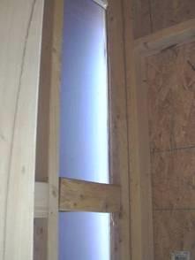
19 Fenestration Chapter 5 Prescriptive Approach Not based on frame types
 Percentage of Vertical Fenestration Area to Gross Wall Area Allowed up to 30% maximum of above grade")
20 Vertical Fenestration Requirement Section C Prescriptive (Max area) Percentage of Vertical Fenestration Area to Gross Wall Area Allowed up to 30% maximum of above grade wall In Climate Zones 1-6, up to 40% maximum of above grade wall with daylighting controls
21 2015 Up to 40% vertical fenestration area allowed in Climate Zones 1-6, provided 40% 40% 40% No less than 50% of the conditioned floor area is within a daylight zone in buildings less than 2 stories above grade No less than 25% of the net floor area is within a daylight zone in building > 3 stories above grade Daylight responsive controls complying with C are installed in daylight zones VT of vertical fenestration is 1.1 times SHGC

22 Skylight Minimum Fenestration Area Section C Prescriptive Limited to 3% of Roof Area Up to 5% allowed if automatic daylighting controls installed in daylight zones under skylights
23 Fenestration Chapter 5 Prescriptive Approach

24 Fenestration SHGC Requirements The Effect of Overhangs on Fenestration SHGC Overhangs allow a higher SHGC product to be installed Projection factor must be calculated When different windows or glass doors have different PFs Evaluate separately Example: A=18 B=84 A/B= 18/84 =.21pf
25 Mandatory Requirements IECC Commercial Envelopes Air Leakage Air barriers Fenestration air leakage Rooms Containing Fuel-burning Appliances Air intakes, exhaust openings, stairways and shafts Loading dock weatherseals Vestibules Recessed lighting

26 Air Barriers and Construction Section C Continuous air barrier required except in Climate Zone 2B Air barrier placement allowed: Inside of building envelope Outside of building envelope Located within assemblies composing envelope OR Any combination thereof
27 Air Barriers and Construction Section C Penetrations of air barrier and air leakage paths to be caulked, gasketed or otherwise sealed in a manner compatible with construction materials and location Joints and seals Sealed in same manner or taped or covered with moisture vapor-permeable wrapping material Sealing of concealed fire sprinklers where required in a manner recommended by manufacturer Caulking or other adhesive sealants should not be used to fill voids between fire sprinkler cover plates and walls, or ceilings Recessed lighting to comply with C Where similar objects are installed that penetrate the air barrier, make provisions to maintain the air barrier s integrity


28 Air Leakage Section C402.5 The thermal envelope must comply with the requirements of Sections C C OR be tested in accordance with ASTM E 779 at pressure differential of 0.3 inch water gauge or an equivalent method approved by code official when tested air leakage rate < 0.40 cfm/ft2
29 Two ways to comply with air barrier requirements: Materials C OR Assemblies C Materials with air permeance cfm/ft2 under pressure differential of 0.3 in. w.g. tested in accordance with ASTM E 2178 Material These materials meet this requirement: Thickness (minimum) Plywood 3/8 in. Oriented strand board 3/8 in. Extruded polystyrene insulation board ½ in. Foil-faced urethane insulation board ½ in. Closed cell spray foam minimum density of 1.5 pcf 1-1/2 in. Open cell spray foam density between 0.4 and 1.5 pcf 4.5 in. Exterior gypsum sheathing or interior gypsum board ½ in. Cement board ½ in. Built up roofing membrane Modified bituminous roof membrane Fully adhered single-ply roof membrane A Portland cement/sand parge, stucco, or gypsum plaster Cast-in-place and precast concrete Sheet metal or aluminum Solid or hollow masonry constructed of clay or shale masonry units 5/8 in.

30 C Air barrier assemblies Option 2 Assemblies of materials and components meeting specific air leakage requirements can comply. 2 items listed as deemed to comply provided joints are sealed Concrete masonry walls coated with either one application either of block filler or two applications of a paint or sealer coating OR Masonry walls constructed of clay or shale masonry units with a nominal width of > 4 OR Portland cement/sand parge, stucco or plaster > ½ thick 30

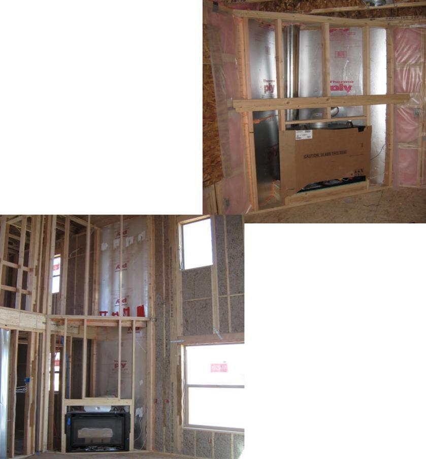
31 Rooms Containing Fuel-burning Appliances Section C Appliances and combustion air openings to be located outside the building thermal envelope or enclosed in a room isolated from inside the thermal envelope in Climate Zones 3-8 Where open combustion air ducts provide combustion air to open combustion space conditioning fuel-burning appliances Rooms to be sealed and insulated per envelope requirements Doors into the rooms fully gasketed Water lines and ducts insulated Combustion air ducts that pass through conditioned space, insulated to > R-8 Exceptions: Direct vent appliances with both intake and exhaust pipes installed continuous to the outside Fireplaces and stoves complying with IMC and Section IBC
32 Commercial Mechanical Size equipment to ASHRAE 183: absolutely no oversizing allowed Mandatory efficiency requirements HVAC System controls Automatic Dampers Ventilation according to IMC Duct and Plenum insulation and Sealing Piping insulation Economizers if using the prescriptive approach Commissioning where required per C408
33 IECC Residential Compliance Options IECC Prescriptive: By the book approach IECC - Prescriptive R U-factor Alternative OR R Total UA alternative IECC Simulated Performance Approach R405 Building Performance based on Building Energy Cost.

34 2015 Prescriptive R-value Table Compliance Specification Declare to the Code official that the pathway for compliance is the prescriptive path Table R
35 R U-factor Alternative CLIMATE ZONE FENESTRATION U-FACTOR SKYLIGHT U-FACTOR CEILING U- FACTOR FRAME WALL U- FACTOR MASS WALL UFACTORb FLOOR UFACTOR BASEMENT WALL UFACTOR CRAWL SPACE WALL U- FACTOR c except Marine and Marine and 8 An assembly with a U-factor equal to or less than that specified in Table R shall be permitted as an alternative to the R-value in Table R Example: Climate zone 5 framed wall U-.060 = R R-value table requires cavity insulation at R20 or /20 = U.05 Plus sheathing, air film, etc.

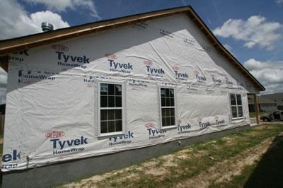
36 Residential Building Thermal Envelope Requirements
 The building or dwelling unit shall be tested and verified as having an air leakage rate not exceeding: 5 ACH@50")
37 R Testing (Mandatory) The building or dwelling unit shall be tested and verified as having an air leakage rate not exceeding: 5 ACH@50 in Climate Zones 1 and 2 3 ACH@50 in Climate Zones 3 through 8 Testing shall be conducted by an approved third party Reporting
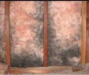
38 402.4 Air Leakage and Air Barriers (Mandatory) The building thermal envelope shall be constructed to limit air leakage in accordance with the requirements of Sections R through R The components of the building thermal envelope as listed in Table R shall be installed in accordance with the manufacturer s instructions and the criteria listed in Table R IECC Table 2015 IECC Table
39 Table Component General Air barrier/thermal barrier Air Barrier Criteria A continuous air barrier shall be installed in the building envelope Exterior thermal envelope contains a continuous air barrier. Breaks or joints in the air barrier shall be sealed Insulation Installation Criteria Air-permeable insulation shall not be used as a sealing material

40 Insulation Insulation traps pockets of air Air Barrier Stopping the movement of air from scrubbing away the stagnate air pocket Stagnate Air Pockets create the R-value Now it works
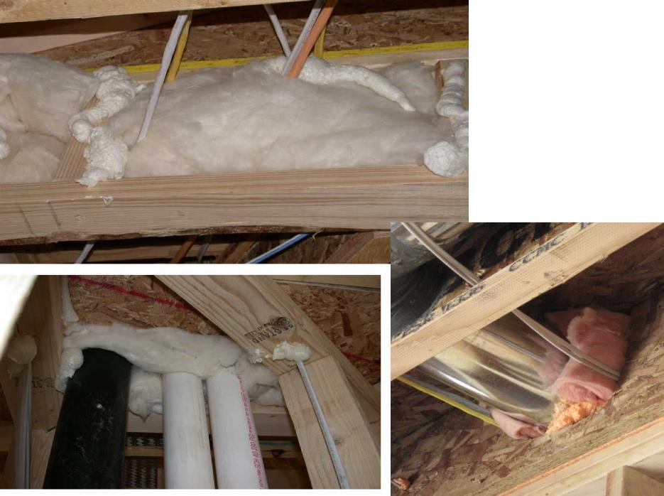
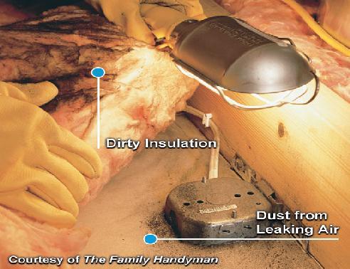
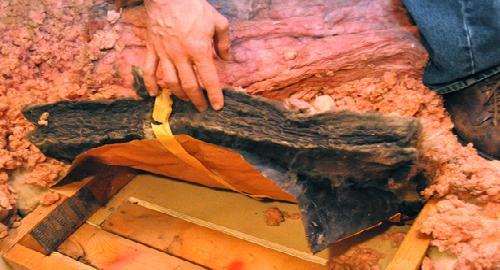
41 Air-permeable insulation shall not be used as a sealing material
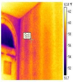
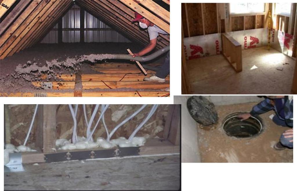
42 Table Component Ceiling / Attic Air Barrier Criteria The air barrier in any dropped ceiling/soffit shall be aligned with the insulation and any gaps in the air barrier sealed Access openings, drop down stair or knee wall doors to unconditioned attic spaces shall be sealed Insulation Installation Criteria The insulation in any dropped ceiling/soffit shall be aligned with the air barrier

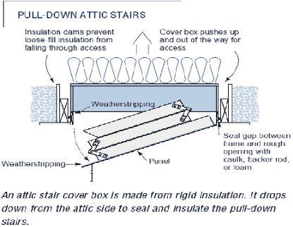
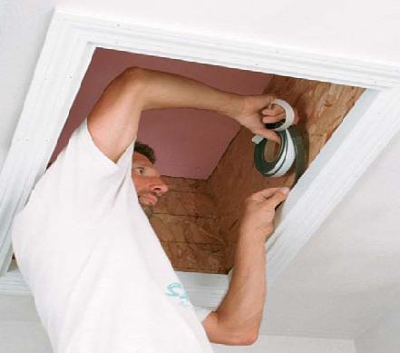
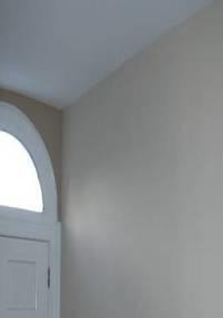
43 Ceiling Access Openings


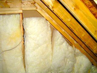
44 R Ceilings with attic spaces R-38 shall be deemed to satisfy the requirement for R-49 wherever the full height of uncompressed R-38 insulation extends over the wall top plate at the eaves. R a is e d H e e l T ru s s B a fflin g to p re v e n t in s u la tio n fro m b lo c k in g v e n tila tio n R-49 R-38


45 R Eave baffle For air permeable insulations in vented attics, a baffle shall be installed adjacent to soffit and eave vents Baffles shall maintain an opening equal or greater than the size of the vent The baffle shall extend over the top of the attic insulation
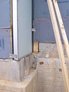
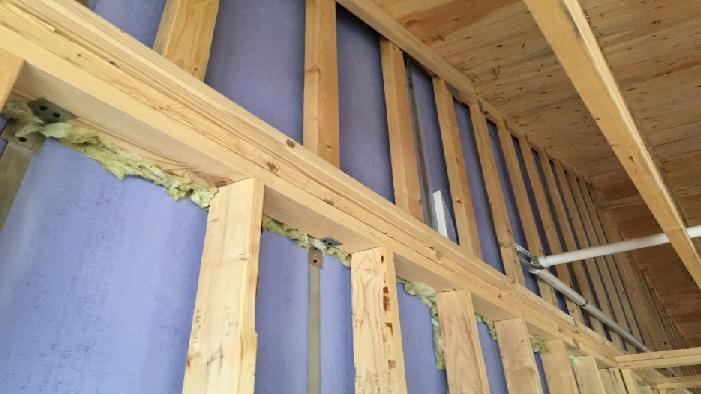
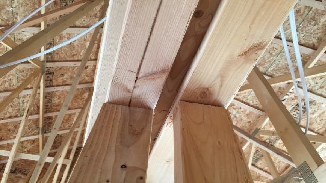
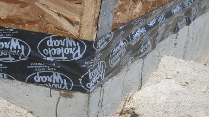
46 Table Component Walls Air Barrier Criteria The junction of the foundation and sill plate shall be sealed The junction of the top plate and top of exterior walls shall be sealed Knee walls shall be sealed Insulation Installation Criteria Cavities within corners and headers of frame walls shall be insulated by completely filling the cavity with a material having a thermal resistance of R3 per inch minimum Exterior thermal envelope insulation for framed walls shall be installed in substantial contact and continuous alignment with the air barrier

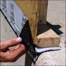
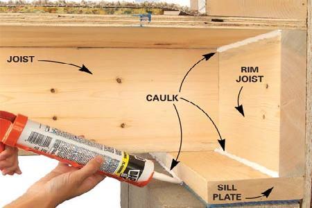
47 Junction of foundation and sill plate is sealed

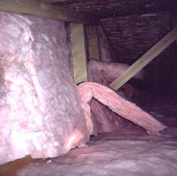
48 Attic Knee Walls


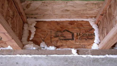
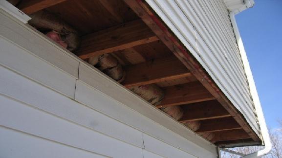
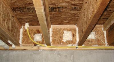
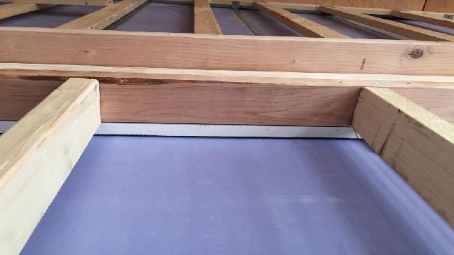
49 Table Component Rim Joists Air Barrier Criteria Rim joists shall include the air barrier Rim Joist Insulation Installation Criteria Rim joists shall be insulated Box Sill
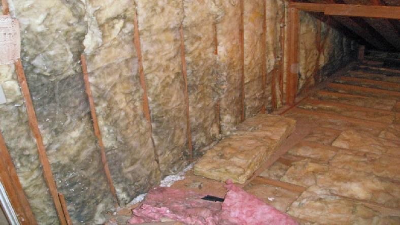
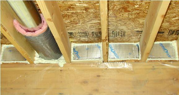
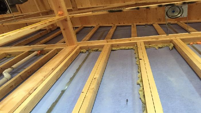
50 Table Component Floors (including above garage &cantilever floors) Air Barrier Criteria Insulation Installation Criteria The air barrier shall be installed at any exposed edge of insulation Floor framing cavity insulation shall be installed to maintain permanent contact with underside of subfloor decking 2015 IECC introduction or floor framing cavity insulation shall be permitted to be in contact with the topside of sheathing or continuous insulation installed on the bottom side of floor framing and extends from the bottom to the top of all perimeter floor framing members.
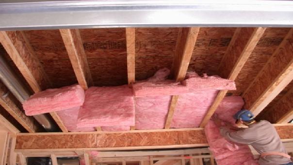
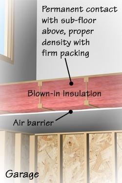
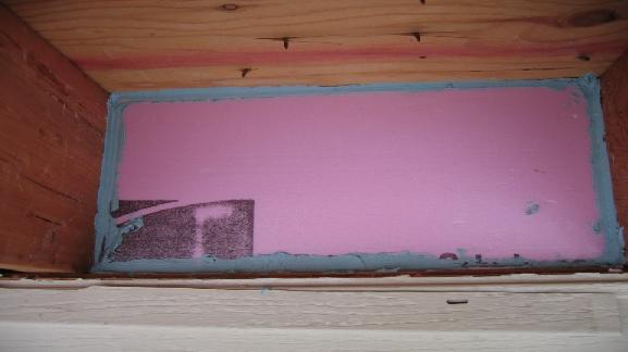
51 Floor Insulation

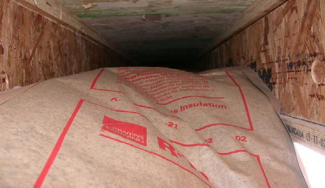
52 The air barrier shall be installed at any exposed edge of insulation Garage/Home Interface: No gaps at ends

53 Details: Cantilever Floor
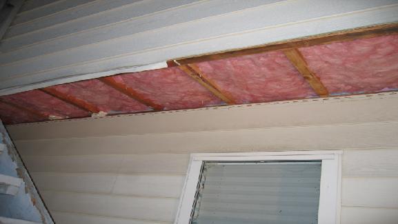
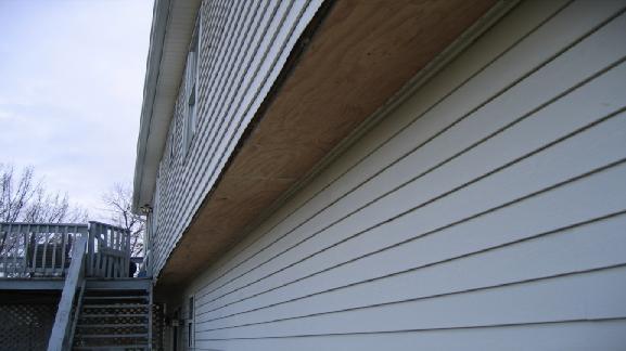
54 Cantilevers Effective detailing
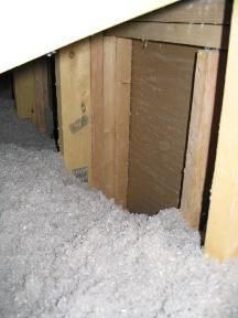
55 Table Component Crawl Space Walls Air Barrier Criteria Exposed earth in unvented crawl spaces shall be covered with a Class I vapor retarder with overlapping joints taped Insulation Installation Criteria Where provided in lieu of floor insulation, insulation shall be permanently attached to the crawlspace walls


56 2015 IECC table Crawl Insulation is permanently attached to walls, earth covered and sealed with Class 1 vapor barrier Sealed Thermal Boundary Mechanically fastened Class I vapor barrier Supply Air

57 Table Component Shafts, Penetrations Air Barrier Criteria Duct shafts, utility penetrations, fireplace chases and flue shafts opening to exterior or unconditioned space shall be sealed Insulation Installation Criteria In the 2015 IECC the Fireplace section was consolidated into this section

58 Table Component Garage Separation Air Barrier Criteria Air sealing shall be provided between the garage and conditioned spaces Insulation Installation Criteria
59 Table Component Shower/tub on exterior wall Air Barrier Criteria The air barrier installed at exterior walls adjacent to showers and tubs shall separate them from the showers and tubs Insulation Installation Criteria Exterior walls adjacent to showers and tubs shall be insulated

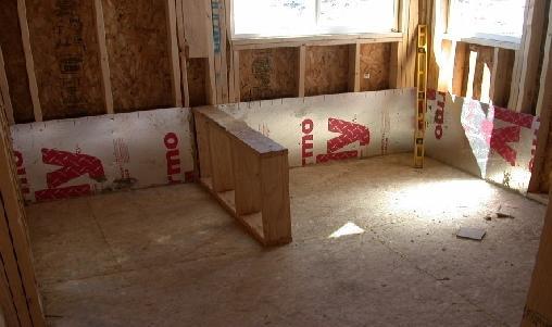
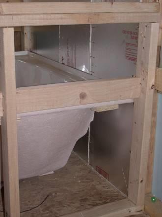
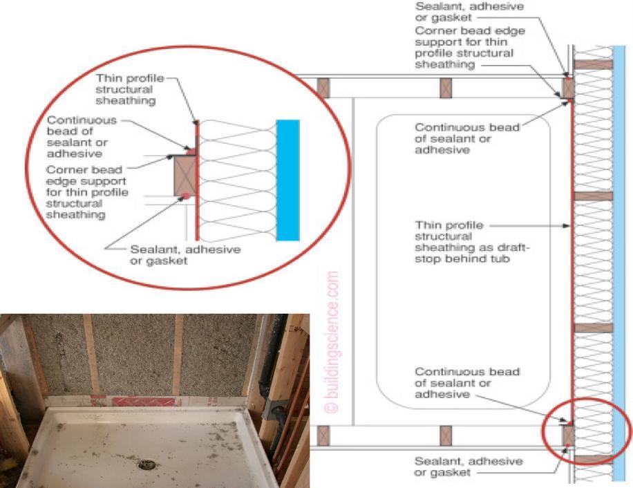
60 Tubs and Showers


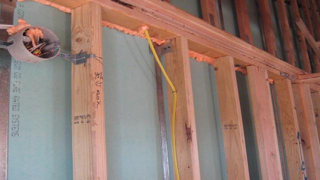
61 Table Component Electrical/phone box on exterior walls Air Barrier Criteria The air barrier shall be installed behind electrical or communication boxes or air sealed boxes shall be installed Insulation Installation Criteria
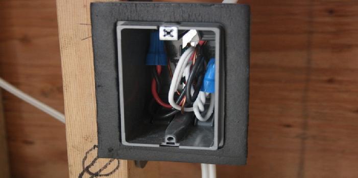
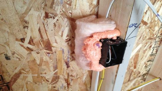
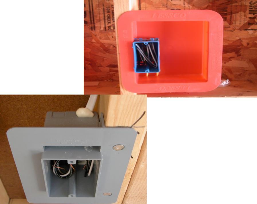
62 Electrical/phone box on exterior walls

63 Table Component HVAC Register boots Air Barrier Criteria HVAC register boots that penetrate building thermal envelope shall be sealed to the subfloor or drywall Who s job is this? Insulation Installation Criteria

64 Table Component Fireplace Air Barrier Criteria This section was moved in the 2015 IECC An air barrier shall be installed on fireplace walls Fireplaces shall have gasketed doors Insulation Installation Criteria
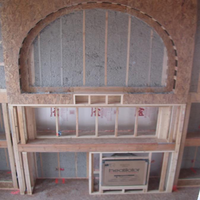
65 Fireplace


66 Sequencing is the Issue air barrier 1st then over framing

67 Table Component Concealed Sprinklers Air Barrier Criteria When required to be sealed, concealed fire sprinklers shall only be sealed in a manner that is recommended by the manufacturer. Caulking or other adhesive sealants shall not be used to fill voids between fire sprinkler cover plates and walls or ceilings Insulation Installation Criteria

68 Building/Fire Code and Energy Code Not on the same page 2009 IECC Common wall: Air barrier is installed in common wall between dwelling units 2012 and 2015 IECC Not mentioned in the table

69 The Problem
70 Common wall between Dwelling Units taken out of the code table Air seal here Energy Code and Building/Fire Code are not in alignment Potential swapping of like materials Framed wall Fire rated foam for rock wool fire stop Blown fiberglass for fiberglass batt Drywall Gap Air seal here
71 What constitutes the assembly?

72 Fill the gap

73 Treat Common / Party Walls Like Exterior Walls and require all air sealing and air barriers adjacent to the assembly


74 Build Tight Ventilate Right
75 M Whole-house mechanical ventilation system M System design: The whole-house ventilation system shall consist of: Supply Side, Exhaust Side, Balanced systems, or combination there of M System controls: The whole-house mechanical ventilation system shall be provided with controls that enable manual override M Mechanical ventilation rate: The whole house mechanical ventilation system shall provide outdoor air at a continuous rate of not less than that determined in accordance with Table M (1). Exception: Permitted to operate intermittently where the system has controls that enable operation for not less than 25-percent of each 4-hour segment and the ventilation rate prescribed is multiplied by the factor determined in accordance with Table M (2).
76 TABLE M (1) CONTINUOUS WHOLE-HOUSE MECHANICAL VENTILATION SYSTEM AIRFLOW RATE REQUIREMENTS Simulated Performance and ASHRAE 62.2 Formula: Ventilation can t be greater than what is calculated by formula Fan flow (CFM) = 0.01 CFM x your floor area x (your number of bedrooms + 1) For a 1,510 square foot 4-bedroom home, (0.01 X 1510) + (7.5 times 5) Formula Result: 52.5 CFM Chart Result: 75 CFM


77 R403.7 Equipment Sizing Heating and cooling equipment shall be sized in accordance with ACCA Manual S based on building loads calculated in accordance with ACCA Manual J or other approved heating and cooling calculation technologies Colorado Code Consulting, LLC 77
78 What s Covered Under Electrical Power and Lighting Systems Requirements? IECC Exception: Dwelling units within commercial building are not required to comply IF they comply with the residential Section R404.1 A minimum of 75 percent of the lamps in permanently installed lighting fixtures are high-efficacy lamps or 75% of permanently installed lighting fixtures contain only high efficacy lamps Exception: Low-voltage lighting
79 Electrical Energy Consumption Mandatory Requirement Section C405.6 Separate metering required for each R-2 dwelling unit
80 Commercial or Residential? That is the question! Who has the answers? NBI DOE Jurisdictions You?

81 QUESTIONS?

82 Thank You!!! Presented by: Shaunna Mozingo Colorado Code Consulting LLC 4610 S Ulster St, Ste 150 Denver, CO direct line smozingo@coloradocode.net