Doç. Dr. Halit YAZICI. D. E. U. Civil Engineering Department.
|
|
|
- Noreen Griffin
- 5 years ago
- Views:
Transcription


1 Doç. Dr. Halit YAZICI D. E. U. Civil Engineering Department
2 PROPERTIES OF HARDENED CONCRETE The principal properties of hardened concrete which are of practical importance can be listed as: 1. Strength 2. Permeability & durability 3. Shrinkage & creep deformations 4. Response to temperature variations Of these compressive strength is the most important property of concrete. Because;
3 PROPERTIES OF HARDENED CONCRETE Of the abovementioned hardened properties compressive strength is one of the most important property that is often required, simply because; 1. Concrete is used for compressive loads 2. Compressive strength is easily obtained 3. It is a good measure of all the other properties.


4
5 FactorsAffectingStrength Effect of materials and mix proportions Production methods Testing parameters
6 STRENGTH OF CONCRETE The strength of a concrete specimen prepared, cured and tested under specified conditions at a given age depends on: 1. w/c ratio 2. Degree of compaction
7
8

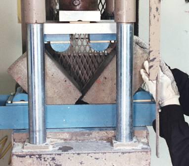
9 COMPRESSIVE STRENGTH Compressive Strength is determined by loading properly prepared and cured cubic, cylindrical or prismatic specimens under compression.
10 COMPRESSIVE STRENGTH Cubic: 15x15x15 cm Cubic specimens are crushed after rotating them 90 to decrease the amount of friction caused by the rough finishing. Cylinder: h/d=2 with h=15 To decrease the amount of friction, capping of the rough casting surface is performed.


11 COMPRESSIVE STRENGTH Cubic specimens without capping Cylindrical specimens with capping


12 COMPRESSIVE STRENGTH Bonded sulphur capping Unbonded neoprene pads
13 The compressive strength value depends on the shape and size of the specimen.
14 Tensile Strength can be obtained either by direct methods or indirect methods. Direct methods suffer from a number of difficulties related to holding the specimen properly in the testing machine without introducing stress concentration and to the application of load without eccentricity.
15

16 Due to applied compression load a fairly uniform tensile stress is induced over nearly 2/3 of the diameter of the cylinder perpendicular to the direction of load application.
17 σ st = 2P πdl Splitting Tensile Strength P: applied compressive load D: diameter of specimen l: length of specimen The advantage of the splitting test over the direct tensile test is the same molds are used for compressive & tensile strength determination. The test is simple to perform and gives uniform results than other tension tests.
18 FLEXURAL STRENGTH The flexural tensile strength at failure or the modulus of rupture is determined by loading a prismatic concrete beam specimen. The results obtained are useful because concrete is subjected to flexural loads more often than it is subjected to tensile loads.

19
20 P d c I = bd3 12 M=Pl/4 b σ = M c I = (Pl/4) (d/2) bd 3 /12 = 3 2 Pl bd 2 P/2 P/2 σ = (Pl/6) (d/2) bd 3 /12 = Pl bd 2 M=Pl/6
21 FactorsAffectingtheStrengthof Concrete 1) Factors depended on the test type: Size of specimen Size of specimen in relation with size of agg. Support condition af specimen Moisture condition of specimen Type of loading adopted Rate of loading Type of test machine 2. Factors independent of test type: Type of cement Type of agg. Degree of compaction Mix proportions Type of curing Type of stress situation

22

23

24
25

26
27 porosity
28

29

30
31
32

33
34

35 STRESS-STRAIN RELATIONS IN CONCRETE σ ult (40-50%) σ ult ε ult σ-ε relationship for concrete is nonlinear. However, specially for cylindrical specimens with h/d=2, it can be assumed as linear upto 40-50% of σ ult
36 MODULUS OF ELASTICITY OF CONCRETE Due to the nonlinearity of the σ-ε diagram, E is the defined by: 1. Initial Tangent Method 2. Tangent Method 3. Secant Method ACI E=15200 σ ult½ 28-D cylindrical comp.str. (kgf/cm 2 ) TS E=15500 W ½ 28-D cubic comp.str. (kgf/cm 2 )
37 PERMEABILITY OF CONCRETE Permeability is important because: 1. The penetration of some aggresive solution may result in leaching out of Ca(OH) 2 which adversely affects the durability of concrete. 2. In R/C ingress of moisture of air into concrete causes corrosion of reinforcement and results in the volume expansion of steel bars, consequently causing cracks & spalling of concrete cover. 3. The moisture penetration depends on permeability & if concrete becomes saturated it is more liable to frostaction. 4. In some structural members permeability itself is of importance, such as, dams, water retaining tanks.
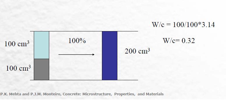
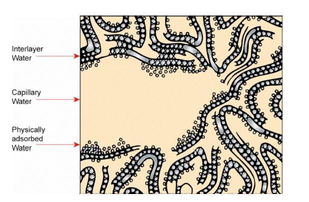
38 PERMEABILITY OF CONCRETE The permeability of concrete is controlled by capillary pores. The permeability depends mostly on w/c, age, degree of hydration. In general the higher the strength of cement paste, the higher is the durability & the lower is the permeability.
39
40 PROPORTIONING CONCRETE MIXTURES W+C+C.Agg.+F.Agg.+Admixtures Weights / Volumes? There are two sets of requirements which enable the engineer to design a concrete mix. 1. The requirements of concrete in hardened state. These are specified by the structural engineer. 2. The requirements of fresh concrete such as workability, setting time. These are specified by the construction engineer (type of construction, placing methods, compacting techniques and transportation)
41 PROPORTIONING CONCRETE MIXTURES Mix design is the process of selecting suitable ingredients of concrete & determining their relative quantities with the objective of producing as economically as possible concrete of certain minimum properties such as workability, strength & durability. So, basic considerations in a mix design is cost & min. properties.
42 Cost Material + Labor Water+Cement+Aggregate+Admixtures Most expensive (optimize) Using less cement causes a decrease in shrinkage and increase in volume stability. Min.Properties Strength has to be more than.. Durability Permeability has to be Workability Slump has to be...
43 In the past specifications for concrete mix design prescribed the proportions of cement, fine agg. & coarse agg. 1 : 2 : 4 Weight of cement Fine Agg. Coarse Agg. However, modern specifications do not use these fixed ratios.
44 Modern specifications specify min compressive strength, grading of agg, max w/c ratio, min/max cement content, min entrained air & etc. Most of the time job specifications dictate the following data: Max w/c Min cement content Min air content Slump Strength Durability Type of cement Admixtures Max agg. size
45 PROCEDURE FOR MIX DESIGN 1. Choice of slump (Table 14.5)
46 PROCEDURE FOR MIX DESIGN 2. Choice of max agg. size 1/5 of the narrowest dimension of the mold 1/3 of the depth of the slab ¾ of the clear spacing between reinforcement Dmax < 40mm

47 PROCEDURE FOR MIX DESIGN 3. Estimation of mixing water & air content (Table 14.6 and 14.7)

48 PROCEDURE FOR MIX DESIGN 4. Selection of w/c ratio (Table 14.8 or 14.9)
49 PROCEDURE FOR MIX DESIGN 5. Calculation of cement content with selected water amount (step 3) and w/c (step 4) 6. Estimation of coarse agg. content (Table 14.10)
50 PROCEDURE FOR MIX DESIGN 7. Calculation of fine aggregate content with known volumes of coarse aggregate, water, cement and air 8. Adjustions for aggregate field moisture
51 PROCEDURE FOR MIX DESIGN 9. Trial batch adjustments The properties of the mixes in trial batches are checked and necessary adjustments are made to end upwith the minimum required properties of concrete. Moreover, a lab trial batch may not always provide the final answer. Only the mix made and used in the job can guarantee that all properties of concrete are satisfactory in every detail for the particular job at hand. That s why we get samples from the field mixes for testing the properties.
52 Example: Slump mm D max 25 mm f c,28 = 25 MPa Specific Gravity of cement = 3.15 Non-air entrained concrete Coarse Agg. Fine Agg. SSD Bulk Sp.Gravity Absorption 0.5% 1.0% Total Moist.Content 2.0% 5.0% Dry rodded Unit Weight 1600 kg/m 3 Fineness Modulus 2.6
53 1. Slump is given as mm 2. D max is given as 25 mm 3. Estimate the water and air content (Table 14.6) Slump and D max W=193 kg/m 3 Entrapped Air 1.5%
54 4. Estimate w/c ratio (Table 14.8) f c & non-air entrained w/c=0.61 (by wt)
55 5. Calculation of cement content W = 193 kg/m 3 and w/c=0.61 C=193 / 0.61 = 316 kg/m 3
56 6. Coarse Agg. from Table D max and F.M. V C.A =0.69 m 3 Dry W C.A. = 1600*0.69 = 1104 kg/m 3 SSD W C.A. = 1104*( ) = 1110 kg/m 3
57 7. To calculate the F.Agg. content the volumes of other ingredients have to be determined. V water = *1000 V cement = *1000 V C.Agg. = *1000 = m3 V air = m 3 (1.5%*1) = m3 = m3 V = M Sp.Gr.*ρ w ΣV = m 3 V F.Agg = = m 3 W F.Agg = 0.278*2.62*1000 = 728 kg/m 3

58 Summaryof MixDesign Based on SSD weight of aggregates
59 8. Adjustment for Field Moisture of Aggregates W SSD =W Dry *(1+a) W Field = W Dry *(1+m) Correction for water From coarse aggregate: = 17 From fine aggregate: = kg extra Corrected water amount : = 145 kg

60 Summaryof MixDesign Based on field weight of aggregates

61 9. Trial Batch Usually a 0.02 m 3 of concrete is sufficient toverify the slumpand air content of the mix. If the slump and air content are different readjustments of the proportions should be made.
62 Cleaning Concrete Surfaces Cleaning methods: Water Chemical Mechanical
63 Finishing Formed Surfaces Rough-form finishes Smooth off-the-form finish Smooth, rubbed finish Sand-floated finish Grout cleandown (sack-rubbed finish)
64 Special Surface Finishes Pattern and Textures Exposed Aggregate Concrete Colored Finishes Stains, Paints and Clear Coatings


65
66 Fiber Reinforced Concrete
67 Effect of fiber
68
69 NEED PCC has low tensile strength, limited ductility and little resistance to cracking PCC develops micro-cracks, even before loading Addition of small, closely spaced and uniformly distributed fibres act as crack arresters. FIBRE REINFORCED CONCRETE is a composite material consisting of mixtures of cement, mortar or concrete and discontinuous, discrete, uniformly dispersed suitable fibres. 69
70 FACTORS AFFECTİNG THE PROPERTIES OF FRC Relative Fibre Matrix Stiffness Volume of Fibres Aspect Ratio of the Fibre Orientation of Fibres Workability and Compaction of Concrete Size of Coarse Aggregate FIBRE REINFORCED CONCRETE Mixing 70
71 1. RELATİVE FİBRE MATRİX STİFFNESS Modulus of elasticity of matrix must be much lower than that of fibre. E.g. steel, glass, carbon Fibres with low modulus of elasticitynylon, polypropylene Interfacial bond between the matrix and the fibres determine the effectiveness of stress transfer 71

72 2. VOLUME OF FİBRES 72

73 3. ASPECT RATİO OF THE FİBRE Aspect Ratio of a fibre = Length/Diameter 73
74 4. ORİENTATİON OF FİBRES The effect of randomness, was tested using mortar specimens reinforced with 0.5% volume of fibres, by orienting them: parallel to the direction of the load perpendicular to the direction of the load in random 74
75 5. Workability and Compaction of Concrete Fibres reduce workability 6. Size of Aggregate Size of CA is restricted to 10mm 75
76 7. MİXİNG Cement content : 325 to 550 kg/m 3 W/C Ratio : 0.4 to 0.6 % of sand to total aggregate : 50 to 100% Maximum Aggregate Size : 10 mm Air-content : 6 to 9% Fibre content vol of mix : 0.5 to 2.5% by : Steel -1% - 78kg/m 3 76 FIBRE REINFORCED CONCRETE : Glass -1% - 25 kg/m 3
77 TYPES OF FRC S 77

78 STEEL FİBRE REİNFORCED CONCRETE (SFRC) Aspect ratios of 30 to 250 Diameters vary from 0.25 mm to 0.75 mm Hooks are provided at the ends to improve bond with the matrix 78

79 FIBRE REINFORCED CONCRETE 79

80 FIBRE REINFORCED CONCRETE 80
81 INTRODUCTION OF STEEL FIBRES MODIFIES: 1. Tensile strength 2. Compressive strength 3. Flexural strength 4. Shear strength 5. Modulus of Elasticity 6. Shrinkage 7. Impact resistance 8. Strain capacity/toughness 9. Durability 10.Fatigue 81
82 APPLICATIONS OF SFRC Highway and airport pavements Refractory linings Canal linings Industrial floorings and bridge-decks Precast applications - wall and roof panels, pipes, boats, staircase steps & manhole covers 82 Structural applications
83 POLYPROPYLENE FIBER REINFORCED CONCRETE (PFRC) Cheap, abundantly available High chemical resistance High melting point Low modulus of elasticity Applications in cladding panels and shotcrete FIBRE REINFORCED CONCRETE 83
84 GLASS FIBER REINFORCED CONCRETE (GFRC) High tensile strength, 1020 to 4080 N/mm 2 Lengths of 25mm are used Improvement in impact strengths, to the tune of 1500% Increased flexural strength, ductility and resistance to thermal shock Used in formwork, swimming pools, ducts and 84 roofs, sewer lining etc.
85 OTHER FIBRES 85
86 ASBESTOS FIBERS High thermal, mechanical and chemical resistance Short in length (10 mm) Flexural strength is 2 to 4 times that of unreinforced matrix Contains 8-16% of asbestos fibres by volume Associated with health hazards, banned in many countries 86
87 CARBON FIBERS Material of the future, expensive High tensile strengths of 2110 to 2815 N/mm 2 Strength and stiffness superior to that of steel 87
88 ORGANIC/VEGETABLE FIBERS Jute, coir and bamboo are examples They may undergo organic decay Low modulus of elasticity, high impact strength 88
89 Load Induced Volume Changes u Instantaneous, 1D σ Tangent modulus σ = E ε Secant modulus ε E γ concrete = unit f' c = = 33γ weight of compressive 1. 5 f' c concrete, lbs strength, / cubic psi ft
90 Load Induced Volume Changes u Time dependant ε Deformation Creep deformation Time
91 Creep in Concrete
92 Creep in Concrete water Creep
93 Consequences of creep u Loss in pre-stress u possibility of excessive deflection u stressing of non load bearing members
94 Economy u Cement Content u 50-60$/ton u Aggregates u 5-6 $/ton u minimum cement required at the minimum water cement ratio, with the maximum strength and durability


95 Shrinkage and Creep
96 Doç. Dr. Halit YAZICI D. E. U. Civil Engineering Department