Assembly and usage instructions REACHMASTER
|
|
|
- Melissa Holmes
- 5 years ago
- Views:
Transcription


1 Assembly and usage instructions REACHMASTER
2 Assembly and usage instructions
3 Assembly and usage instructions 3 Table of contents 1. General information Introduction Manufacturer Type approval Warranty Date of issue Copyright and trademark rights Intended use Improper use 5 2. Setup Safety provisions Usage regulations Working on electrical units with the scaffold tower Technical data General assembly regulations Note on dismantling the scaffold tower Basic dimensions Identification Parts list incl. ballast (see also 3.2) Position of the individual parts Assembly drawings Structural safety regulations General information Attaching the ballast Maintenance, servicing, storage and cleaning Testing the scaffold components Spare parts 24 Notes 27

4 4 Assembly and usage instructions 1. General information 1.1. Introduction These assembly and usage instructions apply exclusively to the scaffold towers described therein. The instructions on safety and the rules and ordinances for the handling of scaffolding in these assembly and usage instructions lie within the area of validity of the scaffold towers referred to in this documentation. Operators bear sole responsibility for: ensuring adherence to the local, regional and national regulations, observance of the regulations (laws, ordinances, guidelines etc.) for safe handling listed in the assembly and usage instructions, ensuring that the assembly and usage instructions are available to operating personnel and that the instructions, information, warnings and safety provisions they contain are followed to the letter Manufacturer The manufacturer of the scaffold towers described in this documentation is 1.3. Type approval ZARGES GmbH Tel.: / Access Technology Division Fax: / PO Box zarges@zarges.de Weilheim Internet: The scaffold towers referred to hereafter have been tested by 1.4. Warranty The scope and period of the warranty type are defined in the manufacturer's sales and delivery conditions. The assembly and usage instructions valid at the time of delivery (see Section 1.5) apply to all warranty claims arising from insufficient documentation. The following applies above and beyond the sales and delivery conditions: The manufacturer accepts no liability for damage to the scaffold towers provided which is caused by one or more of the following: Ignorance of or failure to observe these assembly and usage instructions Insufficiently qualified or instructed operating personnel Failure to use original spare parts. The operator bears sole responsibility for ensuring that the safety provisions as defined in Section 5 are adhered to, that improper use (see Section 1.8), incorrect assembly and setup and unauthorised operation of the scaffold towers are ruled out and that above and beyond this, intended use (see Section 1.7) is ensured and that the scaffold towers are operated in accordance with the application conditions defined in the contract.
5 Assembly and usage instructions Date of issue The date of issue of these English assembly and usage instructions is 01 April Copyright and trademark rights The copyright to these assembly and usage instructions lies with the manufacturer. The manufacturer also reserves all further rights, in particular in the case of the granting of a patent or utility patent registration. Any infringement of the conditions described above will result in liability for damages! 1.7. Intended use The scaffold towers listed in these assembly and usage instructions may only be used as scaffolding in accordance with the stipulations of EN 1004 and the overview of models in these assembly and usage instructions Improper use Misuse - that is, any use of the scaffold towers documented in these assembly and usage instructions which deviates from that described in Section shall be deemed improper use as defined by the Product Safety Act (status ). This also applies to disregard of the standards and guidelines listed in these assembly and usage instructions.
6 6 Assembly and usage instructions 2. Setup 2.1. Safety provisions 1. The stipulations of EN 1004 Mobile work platforms apply to the structural safety, erection and use of the aforementioned scaffold towers. 2. The scaffold towers may only be set up and used by persons familiar with these assembly and usage instructions. 3. At least two persons are required to set up or dismantle the scaffold tower. (Applies to all mobile scaffold towers with a platform height exceeding 2.50m) 4. Undamaged and fault-free original spare parts for the manufacturer's scaffolding system to which the test certificate applies must be used. Before using the scaffold tower, all parts must be examined for correct assembly and functionality. 5. max. 12,0 m max. 8,0 m Under EN 1004, the maximum platform height is 8 m in outdoor use and 12 m in completely enclosed spaces. The maximum platform height for the scaffold towers described in these assembly and usage instructions is 10 m in completely enclosed spaces. 6. The use of lifting tackle on the scaffold tower is not permissible. 7. When setting or and dismantling the scaffold tower, platforms or scaffold planks must be laid flat at a distance of 2 m as assembly aids. Where scaffold planks are used, they must extend 500 mm beyond the scaffold tower on each side. Standing on railings and braces is prohibited, even during setup and dismantling. 8. The scaffold tower may only be set up in vertical position on a horizontal, level surface of sufficient load-bearing capacity. Where necessary, load-distributing pads must be used. 9. Ballast weights, stabilisers and stand-off brackets must be used to ensure structural safety as described in these assembly and usage instructions. 10. Working on the work platform is only permissible with full protection on 3 sides, i.e. guard-rail frame, knee protection and peripheral toeboards. Toeboards are not necessary on the rest platforms.
7 Assembly and usage instructions Working on several work platforms simultaneously is prohibited. 12. When setting up the scaffold tower alongside a wall, stand-off brackets (accessories, Order No ) can be used in addition to ballast. Stop 13. The maximum load-bearing capacity of the scaffold tower with an evenly distributed load is 2.0 kn/m² (in accordance with EN scaffolding category 3). 14. There must be no persons, tools or material on the platform when the scaffold tower is moved. Any impact must be avoided. The scaffold tower may only be moved manually, in longitudinal or diagonal direction and on a firm, level installation surface which is free of obstacles. The scaffold tower must not be moved at more than normal walking speed. 15. Vehicles (e.g. fork lifts) must not be used to move the scaffold tower. The scaffold tower must not be lifted, pulled or pushed using a fork lift. 16. The surface on which the scaffold tower is moved must be capable of bearing its weight. 17. Where the scaffold tower is used outdoors or in open buildings, it must be moved to a wind-sheltered position or secured against tipping over by other suitable means (e.g. 6 anchors) at wind strengths exceeding 6 (on the Beaufort scale), at the onset of a storm and when finishing work for the day. At wind speeds exceeding 6 on the Beaufort scale (12m/s), it becomes perceptibly difficult to walk forwards. 18. The use of planks etc. to bridge gaps between scaffolding and buildings is not permissible. The scaffold tower must not be used as a stair tower to reach other constructions. 19. Before using the scaffold tower, check that it is in vertical position and correct its alignment if necessary. The scaffold tower must also be checked for correct and complete setup as described in Section 2.7.
8 8 Assembly and usage instructions 2.2. Usage regulations 1. Personnel must always climb to the work platform from the inside of the tower. 2. Personnel must not brace themselves against the side protection when working. 3. Jumping on the platforms is prohibited. 4. Horizontal loads which could cause the scaffold tower to tip over must not be generated, for example by working on adjacent constructions. 5. Particular attention must be paid to the wind conditions when using the scaffold towers next to uncovered buildings or building corners to prevent the scaffold towers tipping over. 6. Using ladders, crates or similar means to increase the height of the platform is prohibited. 7. Tools and materials may only be handed upwards. Always take the weight of tools and materials into consideration to avoid overloading the work platform. The person handing the load upwards must not let go of it until the person receiving it has a firm hold on it. 8. Scaffold towers with swivel castors can be moved to their final location after assembly (the ground or floor must not slope by more than 3 %). Any impact must be avoided. When the scaffold tower is in its final position, the alignment must be checked again. 9. When moving the scaffold tower, always take care that it does not touch any live equipment. 10. Electrical tools (drills etc.) may only be operated on the scaffold tower at Safety Extra Low Voltage (48 V), with protective insulation (separation transformer) or if they are connected with a ground fault circuit interrupter with a residual current of 30 ma. 11. Tools and materials must be stored on the work platform in such a way that there is a passageway of 20 cm at the sides of the work platform Working on electrical units with the scaffold tower The scaffold tower must not be used to perform work on or in the vicinity of unprotected live units unless the section of the unit in question has been disconnected, the section of the unit in question has been secured against being switched back on, the section of the unit in question has been checked to ensure that it is not live, the section of the unit in question has been short-circuited with a grounding bar and the section of the unit in question has been shielded against adjacent live parts Technical data 0.68 m x 1.8 m Approved in accordance with EN 1004 Scaffolding category 3 Permissible load in accordance with scaffolding category kg/m² Total maximum load for the scaffold tower 210 kg Maximum platform load 210 kg Maximum platform height 6.50 m
9 Assembly and usage instructions General assembly regulations Fig Fit the swivel castors to the folding frame unit Fig. 1.1 Fig a. Set up the folding frame unit Fig. 2.1 Fig b. Lock folding frame with pin Fig. 2.3 Fig Hook on the platform Position of first platform see different towers at page Fig. 3.1 Fig Attach push-on end frame 1 2 Fig. 4.1 Fig
10 10 Assembly and usage instructions 5. Attach braces Fig. 5.1 Fig a. Attach stabilisers 6 2 Fig. 6.1 Fig b. Attach ballast weights (if necessary!) Fig Attach railing Attach the railing brace at knee height to the stile (vertical) and the upper railing brace to the rung (horizontal) in sitting position through the trapdoor. Fig Put on next frames and platform at next level. (7 rungs higher) Fig. 8.1 Fig. 8.2
11 Assembly and usage instructions Fit top railing in sitting position though trapdoor. Fig. 9.1 Fig For Art.-No and to build up the tower, please use platform at first rung and remove it later to top level. See page 19 and Fit toeboards 1 2 Fig Fig Note on dismantling the scaffold tower To dismantle the scaffold tower, follow the steps for assembly in reverse order. Before commencing dismantling, ensure that the necessary platforms or scaffold planks are installed again and laid flat for personnel to stand on. No part of the scaffold tower (braces, platforms etc.) may be removed before the levels above have been completely dismantled.
12 12 Assembly and usage instructions 2.7. Basic dimensions with stabilisers 42756
13 gepr fte Sicherheit Assembly and usage instructions Identification Art. No. Type plate EN-1004 Gerüstgruppe Scaffolding category Classe d'èchafaudage3 Art. No max. perm. load max. platform height Plattformhöhe Platform height Hauteur plate-forme max. 12,0 m 200 kg/m 2 D max. 8,0 m Achtung: Vor Inbetriebnahme Gebrauchsanleitung und Einsatzbeschränkungen beachten Note: read the user guide and restrictions of use before erection Attention: avant le montage, lisez la notice et les restrictions d utilisations EAN code
14 14 Assembly and usage instructions 2.9. Parts list incl. ballast (see also 3.2) The parts list contains the designations of the individual parts, the corresponding weights, the Art. No. of the individual parts, the number of individual parts contained in the complete scaffold tower and the Art. No. of the complete scaffold tower. It also lists the required ballast for each scaffold tower. Version with stabilisers and ballast weights ( ) Working height approx. [m] Parts list Order No. Folding frame Trapdoor platform rung frame rung-frame rung frame Diagonal brace Horizontal brace Side toeboard End toeboard Stabiliser Swivel castor, Ø125 mm Swivel castor, Ø150 mm, with spindle Number of ballast weights above each swivel castor. Number of ballast weights per attachment point on the stabiliser OUT IN X * * * = heigth at max. adjusted castors X = not permissible Indoor use Outdoor use For : You can use also 4 ballast weights (one on each stile near castors) instead of stabilisers, at indoor-use.
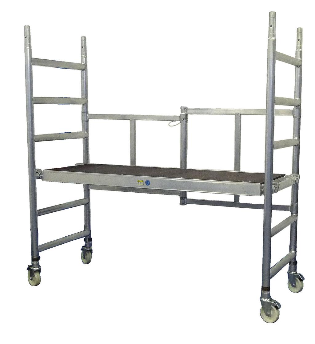
15 Assembly and usage instructions Position of the individual parts Horizontal brace End toeboard Side toeboard Diagonal brace Trapdoor platform Push-on end frame 2 m Triangular stabiliser Folding frame unit Swivel castor
16 16 Assembly and usage instructions Weight Platform height Working height 27.2 kg 0.60 m 2.60 m Name ID No. 1 Folding frame Trapdoor platform Swivel castor Ø125 mm Ballast weights not required! Weight Platform height Working height 36.0 kg 0.90 m 2.90 m Name ID No. 1 Folding frame Trapdoor platform rung frame Horizontal brace Swivel castor Ø125 mm Ballast weights not required!
17 Assembly and usage instructions (IN and OUT) Weight 61.5 kg Platform height 1.70 m Working height 3.70 m Name ID No. 1 Folding frame Trapdoor platform rung-frame Horizontal brace Stabiliser* Swivel castor, Ø125 mm Ballast weights not required! *Stabilisers only required for external use. For indoor-use use 4 ballast weights (one on each stile near castors) Weight Platform height Working height 92.5 kg 2.55 m 4.55 m Name ID No. 1 Folding frame Trapdoor platform rung frame Diagonal brace Horizontal brace Side toeboard End toeboard Stabiliser Swivel castor, Ø125 mm Ballast weights not required!
18 18 Assembly and usage instructions Weight Platform height Working height kg 3.70 m 5.70 m Name ID No. 1 Folding frame Trapdoor platform rung-frame rung frame Diagonal brace Horizontal brace Side toeboard End toeboard Stabiliser Swivel castor, Ø125 mm Ballast weights not required!
19 Assembly and usage instructions Weight Platform height Working height kg 4.50 m 6.50 m Name ID No. 1 Folding frame Trapdoor platform rung frame Diagonal brace Horizontal brace Side toeboard End toeboard Stabiliser Swivel castor, Ø125 mm Ballast weights not required! Attention: To build up the tower, please use platform first at first rung (1) and remove it later to top level (16).
20 20 Assembly and usage instructions Weight Platform height Working height kg *5.90 m *7.90 m Name ID No. 1 Folding frame Trapdoor platform rung-frame rung frame Diagonal brace Horizontal brace Side toeboard End toeboard Stabiliser Swivel castor, Ø150 mm, 10 with spindle Number of ballast weights on each stabiliser. Indoor use Outdoor use 2 * heigth at max. adjusted castors
21 Assembly and usage instructions Weight kg Platform height *6.70 m Working height *8.70 m Name ID No. 1 Folding frame Trapdoor platform rung frame Diagonal brace Horizontal brace Side toeboard End toeboard Stabiliser Swivel castor, Ø150 mm, 9 with spindle Number of ballast weights on each stabiliser. Indoor use Outdoor use 4 * heigth at max. adjusted castors Attention: To build up the tower, please use platform first at first rung (1) and remove it later to top level (23).
22 22 Assembly and usage instructions 3. Structural safety regulations 3.1. General information Chassis beams and stabilisers ensure that the scaffold tower is stable. However, depending on the place of deployment (indoor / outdoor use), these may need to be fitted with ballast weights. Please see the parts lists (Point 2.10) for details of the ballast required Attaching the ballast (on only) Where the ballast weights are attached and how many of them are required will depend on the specific setup and platform height of the scaffold tower. Please refer to the parts lists in Section 2.9 (lower area of the tables) for the precise quantity of ballast required On scaffold towers with stabilisers, ballast weights with fastening clamps (Order No ) must be used. The ballast weights must be attached to the stabiliser as close as possible to the foot of the stabiliser Maintenance, servicing, storage and cleaning The scaffold tower can be cleaned using water with a little household cleaning agent added. Paint spots can be removed using terpentine. Cleaning agent must not be allowed to soak into the soil, and used cleaning solutions must be disposed of in accordance with the relevant environmental protection regulations. Lubricating moving parts Lubricate all moving parts (height adjusters, swivel castor bearings, fasteners) with standard oil. Select a thin-bodied oil when using the scaffold tower in winter. Wipe off superfluous oil. Oil must not be allowed to drip onto steps and platforms - danger of slipping. Dispose of oil-soaked cleaning cloths in accordance with the relevant environmental protection regulations. Storage Ballast weight Order No.: The components of the scaffold tower must be stored in such a way that damage is ruled out. The components of the scaffold tower must be stored in such a way that they are protected from the elements. During transport to and from the place of storage, the scaffold tower components must be secured to prevent sliding and impact. The scaffold tower components must not be thrown during loading or unloading.
23 Assembly and usage instructions Testing the scaffold tower components If defects are ascertained, the affected components must not be used again. Push-on end frame Check for warping, crushing and cracks. Braces (diagonal / railings) Check for warping, crushing, cracks and correct functioning of the fastening elements. Platform Check for warping, crushing, cracks and correct functioning of the fastening elements. Check the condition of the wood. Check trapdoors for correct functioning. Toeboards Check the condition of the wood. Check the toeboards for cracks. Swivel castors Check the castor for smooth running and check that the brake stops the castor rolling or twisting. In the case of swivel castors with height adjusters, also check that the height adjusters move easily. Check the fail-safe device (wing bolt, locking pin) on the chassis beams and basic frame. Stop springs Check for warping, crushing, cracks and correct seating If you require further information or if specific problems occur which are not covered in sufficient detail in these assembly and usage instructions, you can contact the manufacturer directly (see Section 1.2). We would also like to point out that these assembly and usage instructions do not constitute part of or change any previously existing agreement, commitment or legal relationship. All obligations arise from the respective purchase contract, which also contains the complete and solely valid terms of warranty (see also Section 1.4). These terms of warranty in the contract are neither extended nor limited in any way by these assembly and usage instructions. This document may only be passed on to third parties, duplicated or its contents disclosed with the express approval of the manufacturer. Any infringement of the conditions described above will result in liability for damages.
24 24 Assembly and usage instructions 4. Spare parts Folding frame unit: Push-on end frame 2 m, 7-rung: Push-on end frame 1 m, 4-rung: Push-on end frame 1-rung: Trapdoor platform: 42725
25 Assembly and usage instructions 25 Can be identified via: blue claw Diagonal brace: Horizontal brace: Can be identified via: grey claw Triangular stabiliser: Ballast weight: End toeboard: 42749
26 26 Assembly and usage instructions Side toeboard: Swivel castor Ø125 mm: Swivel castor Ø150 mm: 42759
27 NOTES
28 N o EN