LEARNING OF ETABS. 15 ft
|
|
|
- Muriel Wright
- 5 years ago
- Views:
Transcription
1 LEARNING OF ETABS Ram Krishna Mazumder, Institute of Earthquake Engineering Research, Chittagong University of Engineering and Technology, Chittagong 4349, Bangladesh A step-by-step procedure for modeling and analysis of frame structure using ETABS is explained through a simple example. Subsequently an example of seismic analysis of regular frame structure and irregular frame structure are solved manually and through ETABS. Example A plan of five-storied Reinforced Concrete (RC) frame structure is considered for modeling and analysis using ETABS. Beam sizes in Story Height 10 ft Columns sizes in Live Load 40 psf Slab thickness 5 in Floor Finish Load 20psf Concrete grade 3000 psi Steel 60 Ksi 20 ft 20 ft 20 ft 20 ft 5 15 ft 15 ft Y 15 ft X Fig. 1 Plan view of building Earthquake parameters considered are: BNBC 1993 Zone: II Importance Factor 1 Medium type S2 Response Reduction Factor: 6 Elevation of Building Step by step procedure to learn ETABS 1) Modeling using ETABS. 2) Comparison of total DL and LL. 3) Time period and Mode participation factor of building in X and Y direction. 4) Seismic force calculation as per BNBC 1993 a) Static method b) Dynamic method 5) Site specific response spectra 6) Site specific time history 7) Design under gravity and seismic load
 Click the File Menu > New model command Note: we select")

2 Step 1: Modeling using ETABS 1)Open the ETABS Program 2) Check the units of the model in the drop-dow n box in the lower right-hand corner of the ETABS window, click the drop-down box to set units to Kip-in 3) Click the File Menu > New model command Note: we select No because this first model you will built 4) The next form of Building Plan Grid System and Story Data Definition will be displayed after you select NO button. Set the grid line and spacing between two grid lines. Set the story height data using Edit Story Data command


3 5) Define the design code using Options > Preferences > Concrete Frame Designcommand This will Display the Concrete Frame Design Preference form as shown in the figure.


4 6) Click the Define menu > Material Properties Add New Material or Modify/Show Material used to define ma terial properties


5 7) Define section columns and beams using Define > Frame section Define beam sizes and click Reinforcement command to provided concrete cover Define column sizes and click Reinforcement command to provided concrete cover and
")


6 8) Define wall/slab/deck 9) Generate the model Draw beam using Create Line Command and draw column using Create Column command


7 Slab is created using 3 options in which 1 and 3 rd create area in between grid line st draw any shape area, 2 nd draw rectangular area Above creating option used to generate the model as shown in below figure 10) Define various loads (Dead load, live load, Earthquake load)


8 Dead Load: self weight multiplier is used 1 to calculate dead load as default. Live load or any other define load 1 st select the member where assign this load than click the assign button. Assign point load and uniform distributed load Select assigning point or member element than click the assign button


 command")


9 11) Assign support condition Drop-down box in the lower right-ha nd corner of the ETABS window, Select only bottom single storey leve l to assign fixed support using assign> Joint/Point>Restrain (Support) command 12) In building, slab is considered as a single rigid member during earthquake analysis. For that, all slabs are selected first and apply diaphragm action for rigid or semi rigid condition. 13) Mass source is defined from Define > mass source command. Many codes suggested 25% live load to be considered on all floor of building except at roof level.


10 14)Run analysis from Analysis > Run Analysis command Step 2: Comparison of total DL and LL Dead Load Slab lb Beam lb Column lb lb Live Load LL lb Floor Finish Load FF lb

11 In ETABS, dead load and other loads are shown from table as shown in figure. Step 3: Time period and Mode participation factor of building in X and Y direction. Static time period base on BNBC is 0.075H 0.75 = 0.6 sec Dynamic time period as per ETABS analysis is 1.2 sec in X direction and 1.13 sec in Y direction Time period is shown in ETABS from Display > Show Mode Shape Mass participation factor is shown from Display > Show Table > Model Information > Building Model Information > Model Participating Ratio.


12 Bending moment and shear force diagram is shown from Display > Show Member Forces > Frame/Pier/Spandrel Forces command Bending Moment Diagram for Dead Load Shear Force Diagram for Dead Load


13 Select any beam or column member and press right click to shown below figure Step 4: Seismic force calculation as per BNBC 1993/UBC 94. (a) Static Method Define static load from Define > Static load command Press modify lateral load to shown below figure and assign various value as per BNBC 1993/UBC 94


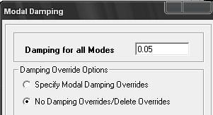
14 (b) Dynamic Analysis Method The design response spectra of BNBC 1993/UBC 94 given as input in the Define menu > Response Spectrum Functions. Response spectra load cases are define in Response Spectrum cases The damping value is specified which is used to generate the response spectrum curve. 5%
 scale factor is assigned as shown in")

15 damping factor and 9.81 (g) scale factor is assigned as shown in Figure Step 5: Site Specific Response Spectra Site specific response spectrum is define from Define > Response Spectrum Function >


16 Spectrum from File. The damping value is specified which is used to generate the response spectrum curve. 5% damping factor and 9.81 (g) scale factor is assigned as shown in Figure


17 Step 6: Site Specific Time History Site specific time history is define from Define > Time History Function


18 Run the analysis and various curves is shown from Display > Show Story Response Plot


19 Step 7: Design under Gravity and Seismic Load Design is carried out using different combination. ETABS have facility to generate combination as per IS Select assigning combination for Design from Design > Concrete Frame Design > Select


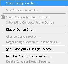
20 Design Combination Design is carried out from Design > Concrete Frame Design > Start Concrete Design

21 Various results in form of percentage of steel, area of steel in column beam is shown from Design > Concrete Frame Design > Display Design Information


22 Select any beam member and le ft click to shown below figure


23 Flexure detailing of beam element is shown in Figure Shear detailing of beam element is shown in Figure


24 Pu-Mu interaction curve, Flexural detailing, shear detailing and beam/column detailing is shown in figure.


25 R K Mazumder, IEER, CUET
26 The END