Tunnel Support Design
|
|
|
- Lindsey Stevens
- 5 years ago
- Views:
Transcription

1 Tunnel Support Design Eric Wang, PE University of Denver Tunneling Short Course September 11, 2018
2 Agenda 1.0 Introduction 2.0 Tunnel Support Design Principles 3.0 Input for Design 4.0 Tunnel Support Systems 5.0 Hard Rock Tunnel Support Design Example 6.0 Soft Ground Tunnel Support Design 7.0 Summary 2

3 1.0 Introduction Design Flowchart sample: (THE Tunnel project) 3


4 2.0 Tunnel Support Design Principles Rock Support Interaction: Optimize support installation - acceptable displacement. Ground vs Support Reaction Curves Ground Reaction Curves based on Overburden Depth 4
5 3.0 Geologic Input for Rock Tunnel Design Rock Mass Classifications: Rock Mass Rating (RMR) System (Bieniawski, 1989) Modified RMR (Laubscher and Page, 1990) NGI s (Q) System (Barton et al., 1974, 2015) Rock Mass Discontinuity Orientation and Properties Rock Hardness, Strength and Abrasiveness for Excavation 5
6 Initial Ground Support Rock Bolts / Dowels Type Length Pattern Anchorage Shotcrete Thickness Type, Dry vs Wet Lattice Girders 6

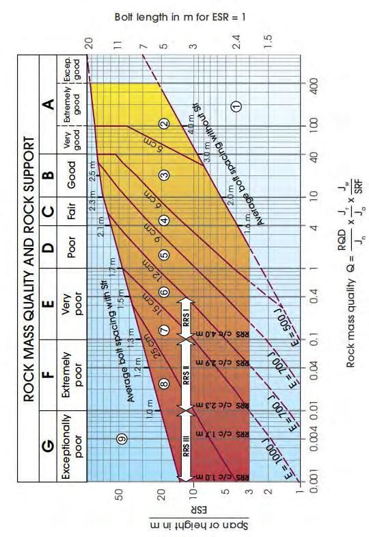

7 Rock Mass Classification Q system After NGI
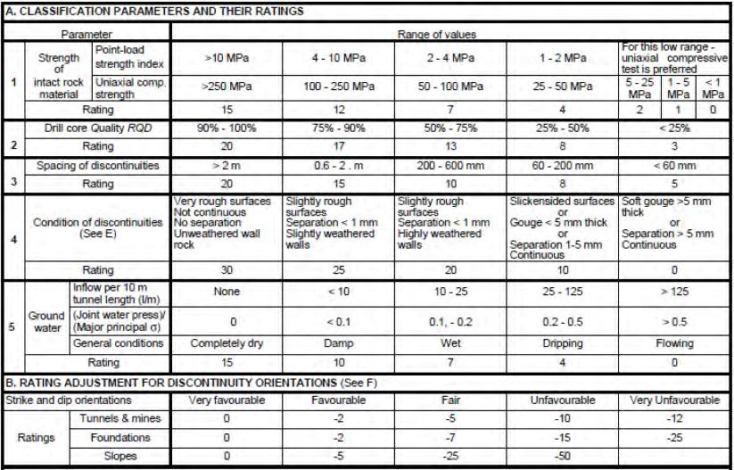

8 RMR Classification 8
 Rock Reinforcement (Bischoff and Smart) Numerical")
9 Tunnel Support Design Support Estimate: Empirical Approach Analytical Approach Kinematic (Block stability) Rock Reinforcement (Bischoff and Smart) Numerical Modeling 9
10 Empirical Methods Terzaghi s Rock Load (conceptual) More conservative Modified by Deere et al.,
11 Empirical Methods Graphical Ubiquitous Joint Method (No. 7 Subway Line Extension) 11
 Cavern cross-section wedge formation and initial support pattern (No.")
12 Kinematic Approach Jointed Rock Mass DIPS and UNWEDGE software (Rocscience) Stereonet of structural discontinuity planes (No. 7 Subway Line Extension) Cavern cross-section wedge formation and initial support pattern (No. 7 Subway Line Extension) 12


13 Numerical Modeling Example THE Tunnel 34 th Street Station Cavern Station Cross section (THE Partnership) Station Longitudinal section (THE Partnership) 13
14 Numerical Modeling Example THE Tunnel 34 th Street Station Cavern Excavation Sequence: Stage 1: Excavation of four TBM tunnels (TBM1, 2, 3, and 4) through the station cavern Installing initial ground supports behind TBM shield as required. TBM1 TBM2 TBM3 TBM4 Station Cavern Excavation (THE Partnership) 14
15 Numerical Modeling Example THE Tunnel 34 th Street Station Cavern Excavation Sequence: Stage 2: Excavation of Top-heading ( Side-drift 1, Side-drift 2, and Center-drift 3) Stage 3: Excavation of Benches and Inverts (4, 5, 6, 7, 8 and 9) Installing initial ground support after excavation of each blast round including rock bolting and shotcreting. TBM1 TBM2 TBM3 TBM4 Full excavation sequence 15

 Initial Support Stiffness Length of Unsupported")
16 Numerical Modeling Example THE Tunnel 34 th Street Station Cavern Partially release of stress at the face of excavation at each excavation round before installing initial support. Evaluate stress release considering forces on ground and lining: Size of Excavation Face Ground Stiffness (Elastic Modulus, Poisson s ratio) Initial Support Stiffness Length of Unsupported Excavation Round (after Hoek) 16

17 Numerical Modeling Example THE Tunnel 34 th Street Station Cavern Stress release for each excavation step before installing initial support in the model: TBM1 = 10%, TBM2 = 10%, TBM3 = 10%, TBM4 = 10% Side-Drift1 = 30%, Side-Drift2 = 30% Center-Drift3 = 40% Bench4 = 50%, Bench5 = 50% Bench6 = 50%, Bench7 = 50% Invert8 = 50%, Invert9 = 50% Final Lining = 100% relaxation At the final stage: Eliminating the initial supports 17
 E ground = Stress / Strain Installing initial support for each stage after simulating the strains in the numerical model (THE Partnership - ILF)")
18 Numerical Modeling Example THE Tunnel 34 th Street Station Cavern Simulate excavation sequence Consider ground strain due to excavation at each Stage (Estimate stress release at each stage) E ground = Stress / Strain Installing initial support for each stage after simulating the strains in the numerical model (THE Partnership - ILF) 18
 General Station Cavern Excavation combining TBM and SEM Enlargement Top heading / Bench / Invert (THE Partnership - ILF)")
19 Numerical Modeling Example THE Tunnel 34 th Street Station Cavern Top heading / bench / invert excavation at Final Stage (prior to removing the initial support) General Station Cavern Excavation combining TBM and SEM Enlargement Top heading / Bench / Invert (THE Partnership - ILF) 19


20 Numerical Modeling Example THE Tunnel 34 th Street Station Cavern Total displacement contours with deformation vectors and deformed boundaries Contours of yielded elements (THE Partnership - ILF) 20

21 Numerical Modeling Example THE Tunnel 34 th Street Station Cavern After Elimination of Initial Support Contours of yielded elements Axial Forces Bending Moments (THE Partnership - ILF) 21
22 Ground Support Ground support classes Pre-support Ground Treatment / Ground improvement 22
23 Ground Support Classes Contract - Typically 2 to 3 initial support classes Hard rock TBM example: Support Class I: Pattern rock dowels TUNNEL CENTER Support Class II: Additional mine-straps and/or shotcrete support TUNNEL CENTER Support Class III: Steel rib support TUNNEL CENTER ROCKBOLT ROCKBOLT W6X25 STEEL RIB 6'-00" 4'-00" 160 TUNNEL AXIS 120 6' TOE BOLT 23
24 Tunnel Support Systems Hard Rock Available Tunnel Support Systems Rock bolts Rock Anchors Rock Dowels Mine straps Shotcrete plain and reinforced (either steel fibers or WWF) Soft Ground Available Tunnel Support Systems Soil Nails Rebar / Pipe Spiling Lattice Girders Shotcrete Cast-In-Place 24
 CIP Lining Double shield EPB / Slurry Face Available Tunnel Support Systems Segmental lining Annular and Secondary Grouting")
25 Tunnel Support Systems Open (Gripper) TBM Available Tunnel Support Systems Rock bolts / Rock dowels Steel Ribs with channel lagging or minestraps Shotcrete (limited to extremely poor ground) CIP Lining Double shield EPB / Slurry Face Available Tunnel Support Systems Segmental lining Annular and Secondary Grouting 25


26 Ground Support through Shear Zone Steel mat lagging WWF and minestraps Spiling and shotcrete 26
")

27 Pre-support Systems Spiling (Fore-poling) Pre-grouting ahead of face Double-roof pipe canopy arch 27

28 Canopy spiling at Portal 28


29 Ground Treatment Ground freezing Pre-Grouting 29

30 Groundwater Control Tunneling infiltration control and waterproofing systems Pre-excavation grouting of open fracture (South River Tunnel, Atlanta, GA., 2011) 30
31 Tunnel Grouting CEMENTITIOUS vs. POLYURETHANE GROUTS CEMENTITIOUS: Dry, open joints Long-term strength POLYURETHANE: Wet conditions or relatively narrow fissures Time dependent properties Flow behavior (unreacted & reacting) 31
32 Tunnel Grouting Pre-excavation Combined Cement + Water-reactive Polyurethane Grout: Steps 1. Polyurethane (TACSS single component prepolymerized polyurethane) reaches permeable rock mass forms barrier upon reacting with water 2. Subsequent Cement grout able to begin filling crack and curing with dilution from leaky crack. 32

33 5.0 Example - Pillar Stability Evaluation Phase 2D -Pre-support considered Staged Excavation Results No significant yielding & deformations at 60% gripper pressure Localized spalling of Starter Tunnel shotcrete lining at 30% gripper No impact on Global Stability 33

34 Pillar Stability Evaluation Proposed T302 34

35 Pillar Stabilization Measures 35


36 Starter Tunnel Rock Reinforcement Brow and gripper wall support Cradle for TBM launch 36
37 Starter Tunnel Rock Reinforcement 37


38 Starter Tunnel Rock Reinforcement 38
39 Shotcrete Support Design In Blocky ground Prevent rock mass raveling and loosening between bolts Typical failure modes: Adhesive Direct Shear Flexural Punching Shear Applied Load Model -Shotcrete Support (after Barrett and McCreath, 1993) 39
 Adhesive failure model (after Barrett and McCreath,")
40 Failure modes (blocky ground): Adhesive failure Shotcrete Support Design Failure mode (after Barrett and McCreath, 1993) Adhesive failure model (after Barrett and McCreath, 1993) 40
 Direct Shear failure model (after Barrett and McCreath,")
41 Failure modes (blocky ground): Direct Shear Failure Shotcrete Support Design Failure mode (after Barrett and McCreath, 1993) Direct Shear failure model (after Barrett and McCreath, 1993) 41
42 Failure modes (blocky ground): Flexural failure Shotcrete Support Design Failure mode (after Barrett and McCreath, 1993) Flexural failure model (after Barrett and McCreath, 1993) 42
 Punching Shear failure model (after Barrett and McCreath,")
43 Failure modes (blocky ground): Punching Shear failure Shotcrete Support Design Failure mode (after Barrett and McCreath, 1993) Punching Shear failure model (after Barrett and McCreath, 1993) 43

44 Shotcrete Support Design Good bond between rock and shotcrete Direct Shear Failure unlikely Adhesion Failure > 4m spacing Type equation here. Adhesive failure model (after Barrett and McCreath, 1993) 44

45 Shotcrete Support Design Poor bond between rock and shotcrete Direct Shear Failure unlikely Adhesion Failure > 2.25 m spacing (after Barrett and McCreath, 1993) 45
 Timely groundwater")

46 Soft-ground Tunneling Continuous support of face and periphery (invert) Timely groundwater control Vacuum Drain Flowing Ground Horizontal vacuum system (after Taiwan HS Rail, ) 46


47 Soft-ground Tunneling 3D tunnel convergence monitoring vertical and transverse Reference THSR: 40-ft diam SEM tunnel Vertical Backfilled Invert Lateral 47

48 Soft-ground Tunneling Continuous tunnel convergence monitoring - longitudinal Longitudinal Reference THSR: 40-ft diam SEM tunnel 48
49 Face bolting and Ring Cut in Sandy Ground 49


50 Face bolting and Ring Cut in Sandy Ground 1. Face Bolting 2. Partial Excavation 50
 Contact Grouting of Arch 3. Temp.")
51 Face bolting and Ring Cut in Sandy Ground Running Ground Periodic sealing (accelerator) Contact Grouting of Arch 3. Temp. Sealing 51
52 Protection of Adjacent Structures Identify reinforcement/ underpinning needs Instrumentation & Monitoring Program Control Ground movement /Subsidence Rigid Water-tight Excavation Support under construction as well as permanent conditions 52
53 Building Impact Assessment - Procedure 1. Initial screening 2. Develop settlement profile 3. Evaluate settlement profile per project criteria (max surface settlement, impact to structures, etc.) 4. Identify sensitive structures within influence zone - more comprehensive analysis 5. Mitigation measures construction restrictions 53
 adjacent highway slight embankment shallow (30-ft) cover 3. Lower Silver Creek shallow cover settlement cracking of liner leaking shallow (30-ft) cover TransPak 0.8 0.8 1.")
54 Settlement Contour Map at East Portal Protection of Existing Structures Potential Impacts 1. TransPak (Shipping depot - single-story warehouse bldg.) settlement shallow (35-ft) cover 2. Bayshore Freeway (Route 101) adjacent highway slight embankment shallow (30-ft) cover 3. Lower Silver Creek shallow cover settlement cracking of liner leaking shallow (30-ft) cover TransPak
 embankment footing and adjacent pile foundation. 2. Shallow cover (+/- 40 FT) overlying single-story building i.e., All-World Furniture and Deka Batteries settlement potential.")
55 Settlement Contour Map at West Portal DEKA BATTERIES Protection of Existing Structure 1. I-880 Nimitz Freeway Overpass, Shallow cover (+/- 40 FT) embankment footing and adjacent pile foundation. 2. Shallow cover (+/- 40 FT) overlying single-story building i.e., All-World Furniture and Deka Batteries settlement potential. ALL WORLD FURNITURE


56 Building Impact Evaluation 56
57 Potential Mitigation Options Further evaluation of specific existing structures based upon ground conditions and as-built foundation data, potential mitigation options could feature: Structural Underpinning, Grouted Canopy spiling and lattice girder Rigid Support of Excavation Systems (Secant pile walls, etc.) Ground treatment A critical issue in design of mitigation measures is avoiding the creation of hard points in the building that can focus and amplify building response or damage. (Boscardin and Walker, 1998) 57
58 Tunnel Support Design Summary Summary Project-specific ground characterization Compatible excavation methodology Hard rock tunnel: rock mass discontinuities, strength and abrasion Soft-ground tunnel: continuous face and periphery support/ GW control / monitoring Contingency Risk Mitigation measures: pre-support / ground treatment/ temporary invert support Optimize support design evaluate results from several analytical approaches 58

59 Questions? Mile-high thank you for your attention! 59