ENGLISH INSTALLATION GUIDE
|
|
|
- Maximillian Parks
- 5 years ago
- Views:
Transcription

1 ENGLISH INSTALLATION GUIDE

2 » Strong, safe and non-combustible» Rot- and termite-proof steel lasts much longer than wood» Precise engineering enables curved deck designs and flat surfaces» Contains a minimum of 5% recycled steel and is a 00% renewable resource» Backed by the Trex 5-Year Limited Residential Warranty framing: Trex Elevations decking: Transcend in Spiced Rum & Vintage Lantern railing: Transcend in Classic White & Vintage Lantern with round aluminum balusters also featuring: Trex DeckLighting and TrexTrim

3 General information Installation Guide In your hands, you re holding everything you need to begin building with Trex Elevations steel deck framing system. This step-by-step guide will show you how to create a beautiful outdoor living space that fits perfectly into your or your client s lifestyle. Trex has been proven in the field. After almost twenty years of unparalleled performance, it offers warm, natural beauty and inviting comfort that no other product can match. Maybe that s why Trex is asked for by more customers than any other brand in the business. From time to time, Trex revises its installation instructions. To ensure you have the most up-to-date installation instructions, please visit trex.com. 3
4 General information Trex ELEVATIONS Installation Guide Contents SECTION ONE: General Information General Questions and Answers...5 Safety...6 Tools, Fasteners, and Brackets...6 Parts...7 SECTION TWO: Preparation and Planning Planning...9 Code Compliance...9 Table E-50 Span Chart (Total Load 50 PSF)... Table E-75 Span Chart (Total Load 70 PSF)... 4 Table E-00 Span Chart (Total Load 00 PSF)... 6 Table E-00 Span Chart (Total Load 00 PSF)...8 SECTION THREE: Installation Installing Piers, Posts, Track/Ledger, and Beams... Installing Piers and Posts... Installing Track/Ledger... Installing Beams... Option : Flush Beam Scenario... Option : Single Beam Notched Post Scenario... Option 3: Single Flush Post Beam Scenario... Option 4: Double Drop Beam Scenario... 3 Installing Rim Joists, Joists, Rim Plates, and Joist Blocking...4 Installing Rim Joists Assembly...4 Installing Inner Joists...4 Option : Flush Beam Scenario... 5 Option : Drop Beam Scenario... 5 Installing Rim Plate and Joist Blocking (Drop Beam Scenario Only)... 5 Installing Blocking... 5 Installing Rail Posts... 6 How to Install Deck Boards...7 Tips on Installing Deck Boards over Screws on Ledger/Front Plate...7 Installing Butt Seams...7 Installing Angled Deck Boards in Corners... 8 Option : Traditional Face Screwing... 8 Option : With Trex Elevations Universal Hidden Fasteners... 8 Installing Start Clips and First Board... 8 Installing Universal Fasteners... 8 Installing Second Board... 9 How to Complete the Trex Elevations Framework... 9 How to Install Trex Elevations Stairs How to Install Deck Boards and Fascia on Elevation Stairs Tip on Installing Deck Boards over Screws on Stair Sections Installing Deck Boards...37 Installing Risers...37 Fascia Installation Options...37 Installing Fascia...37 SECTION FOUR: Detail Drawings General Framing Detail Nominal TYP. Ledger Connections... 4 Flush Beam Attachment Scenario Joist Attachment Sharing Flush Beam Scenario Dropped Beam Notched Post Attachment (Wood Post Only) Double Dropped Box Beam Atop Post Attachment Deck Level Change Flush Beam Scenario...47 Deck Level Change Scenario Deck Level Change Ledger Attachment to Support Post Inside Rail Post Attachment at Rim Joist Inside Rail Post Attachment at Corner... 5 Inside Rail Post Attachment at Rim Plate... 5 Stair Overview Diagram Stair Post Support Stair Box Assembly Stair Stringer Assembly Stair Railing Post Attachment...57 Stair Center Stringer Assembly Wood Stair Attachment to Rim Plate of Rim Joist Cap Standard Blocking Adjustable Blocking... 6 Y Bracing Post to Beam... 6 Border Plank Framing Breaker Board Framing TYP. Single Break Breaker Board Framing TYP. Double Break General Framing Detail Curved Front Track Rim Plate Joist Splice Over Dropped Beam...67 General Framing Detail Joist Perforations Deck Framing Detail (Grounding) General Framing Detail Trex Rain Escapes Blocking Atop BM SECTION FIVE: Maintenance Maintenance...7 SECTION SIX: Warranty Trex Elevations Limited Warranty...74 Comparison Chart...Inside Back Cover NOTE: Construction methods are always improving. Please ensure you have the most up-to-date installation instructions by visiting: trex.com 4 This symbol indicates page information continues to next page.
5 General Questions and Answers Why Trex Elevations?» Strong Elevations provides for a larger deck space with fewer posts and beams for less obstructed views.» Stable Elevations won t twist, warp or sag over time.» Long-lasting Elevations lasts longer than pressure-treated lumber, saving you the cost of fixing or replacing your deck.» Non-combustible Elevations is ideal for areas of high-density housing and frequent wildfires.» Eco-friendly Elevations contains a minimum of 5% recycled steel and is 00% recyclable. How easy is Trex Elevations to build with? Trex Elevations lays out quickly and easily. There are only three components: () Trex Elevations Track (Ledger), () Trex Elevations Joist, and (3) Trex Elevations Beam» Each piece can be cut to fit and assembled just like wood.» Features premium ' (3.66 m), 6' (4.88 m), and 0' (6. m) lengths for track and ledger. Lengths for.joists range from 8' (.44 m) to 0' (6. m) in ' (0.305 m) increments.» Trex Elevations is assembled using hex head self-drilling screws and common angle brackets.» Trex Elevations requires fewer tools (a circular saw, drill, and ferrous metal blades) compared to typical wood framing. As a preventative, as well as an aesthetic measure, always paint exposed steel with Precision Color by Quest Industrial/Raabe Brown Textured touchup paint. ( ) ext. 565 Helpful Hint: Do this after you have cut a large number of components in order to speed up the process. Can scrap Trex Elevations cut-offs be recycled? Trex Elevations components contain a minimum of 5% recycled steel and cut-offs are 00% recyclable. Can Trex Elevations be used in high fire danger areas? Trex Elevations components are non-combustible and qualify for extreme wild fire building codes under the Wild Land Urban Interface (WUI) building material requirements. What is the proper method to store Elevations? Elevations should be supported at a sufficient height to avoid full ground contact if at all possible. Heat and cold transfer to any steel product can sometimes damage lawn and vegetation. General information What tools are required? Go to page 6 for a complete description of the tools, hardware, and connectors required for installing a Trex Elevations steel deck frame. Are there color choices in Trex Elevations? Trex Elevations steel deck framing is available in ONE unique color that is designed to provide a pleasing and subtle shadow effect under the deck, drawing visual attention to the detail elements of your deck. What type of maintenance is required with Trex Elevations? Trex Elevations is low maintenance when installed properly. The dual-coated finish protects the steel, insulating it from outdoor elements. When the steel in Trex Elevations is exposed, in the case of an end cut or scratch, does it need to be painted? Yes. Each steel component is galvanized and coated with a specially formulated exterior finish that is primed, painted, and baked on exclusively engineered for the durability of Trex Elevations.» If scratched and not painted, the galvanization process will restrict rust. Rust will be electromagnetically restricted to only the area exposed. Can Elevations components come into contact with soil or concrete when installed? Trex Elevations is approved for contact with both soil and concrete. What fasteners can I use to attach Trex Decking to Elevations framing? Only use Trex Elevations approved fasteners when installing any decking product. Use of non-recommended decking fasteners could void warranty. Refer to Trex Elevations Required Fasteners on page 6 for details. WARNING Due to increased risk of corrosion, Trex Elevations may not be installed () within 3000 ft. (94.4 m) of any body of salt water or () under the surface or within the splash zone of any body of fresh water. Any such installations shall void the Trex Limited Warranty. Note: Grounding Trex Elevations When required by local code officials, properly ground Trex Elevations. Refer to page 69 for more details. Quest Industrial/Raabe is a registered trademark of Quest Industrial/Raabe Corporation. 5
6 General information Safety WARNING When working on any construction project, you should wear protective clothing and safety equipment. Wear face shield, hearing protection, gloves, and long sleeves, particularly when cutting in confined spaces. Tools Fasteners and Brackets Tape measure Permanent felt marker C-channel vice grips» Dual Hardness Self-Drilling Steel Framing Screw refer to Trex Elevations Required Fasteners, column A (shown below).» Galvanized 6 Ga. L bracket (Simpson Strong-Tie L70Z, LS70Z or IBC approved equivalent). 7-/4" (8.4 cm) Circular saw Drill with adjustable clutch and torque with speed range of 0-,500 max. L70Z LS70Z» Galvanized 6 Ga. post bracket (Simpson Strong-Tie AC4Z, LCP4Z, AC6Z, LPC6Z, or IBC.approved equivalent). 7-/4" (8.4 cm) Ferrous metal cutting blade AC4Z or AC6Z LPC4Z or LPC6Z Step drill bit Precision Color by Quest Industrial/Raabe Brown Textured touch-up paint Note: For post to pier connections, refer to local building code official for proper installation methods. Simpson Strong-Tie is a registered trademark of Simpson Strong-Tie Company, Inc. Refer to for important installation and corrosion information. Trex Elevations Required fasteners Column A Column B Column C Metal-to-Metal Decking to Metal Face Attachment Decking to Metal Hidden Fasteners Simpson Strong-Tie XEQ34B06 ITW Buildex Teks Select P/N (0-6 x ¾" [.9 cm] HWH Teks 3) FastenMaster Cortex Driller * Starborn DeckFast Metal 40 SS w/ Epoxy Coating Trex Elevations Universal Hidden Fasteners Simpson Strong-Tie Quik Drive DCSD38 (xxxx) *xxxx denotes color code of product 6 * After installing FastenMaster Cortex Driller screws, gently tap Cortex plugs into place to cover screws. FastenMaster Cortex Driller is a registered trademark of OMG, Inc. DeckFast is a registered trademark of Starborn Industries, Inc. Teks Select are trademarks of ITW Buildex and Illinois Tool Works, Inc.
 (4. cm x 0.3 cm) Trex Elevations Joist 8' (.44 m) CG00808EJ0 9' (.74 m) CG00809EJ0 0' (3.05 m) CG0080EJ0 ' (3.35 m) CG008EJ0 ' (3.66 m) CG008EJ0 3' (3.96 m) CG0083EJ0 4' (4.")
7 PARTS COMPONENT.5" x 8.5" (nominal) (3.75 cm x 0.7 cm) Trex Elevations Track/Ledger DESCRIPTION ITEM NUMBER ' (3.66 m) CG0Q08ET0 6' (4.88 m) CG0Q086ET0 0' (6. m) CG0Q080ET0 General information.65" x 8" (nominal) (4. cm x 0.3 cm) Trex Elevations Joist 8' (.44 m) CG00808EJ0 9' (.74 m) CG00809EJ0 0' (3.05 m) CG0080EJ0 ' (3.35 m) CG008EJ0 ' (3.66 m) CG008EJ0 3' (3.96 m) CG0083EJ0 4' (4.7 m) CG0084EJ0 5' (4.57 m) CG0085EJ0 6' (4.88 m) CG0086EJ0 7' (5.8 m) CG0087EJ0 8' (5.49 m) CG0088EJ0 9' (5.79 m) CG0089EJ0 0' (6. m) CG0080EJ0 " x 8.5" (nominal) (5.08 cm x 0.7 cm) Trex Elevations Beam ' (3.66 m) CG008EB0 6' (4.88 m) CG0086EB0 0' (6. m) CG0080EB0 Deck Support Post for Trex Elevations Track/Ledger As part of the Trex Elevations steel deck framing system, steel support posts prevent buckling and maintain an even perfection from the day they re installed. These galvanized steel posts can either be painted or wrapped to complement the deck, rail, and home. Track Beam Post Joists Refer to for full details on installation of this product. elevations Product weights Profile lb/ft lbs/piece ' 6' 0' Joist Track Beam

8 Preparation and planning PREPARATION and PLANNING 8

9 Planning WARNING Trex Elevations does not provide direction on making all types of connections. Specific details for critical connections not shown should be designed by a professional engineer and/or building code official. WARNING Build according to local building codes. Refer to section R505 of the 006 or 009 IRC for more information. WARNING Reference all decking, railing, and deck accessory manufacturers for required attachment and installation procedures regarding their products. In order to build a deck with Trex Elevations components, it is necessary to determine the adequate joist span and beam span of your deck from the illustrations shown on page. It is also necessary to determine if a cantilever (i.e. overhang) is desired (or required) to attain the desired deck depth. Determine whether a drop beam or flush beam scenario will be used and determine the required information for local building plan approval. Choose the Trex Elevations span chart (refer to pages -9) that fits within the building code requirements by locating the live, dead, and total load in the Uniform Deck Loads chart. If you do not know the local code requirements, contact your local building code department for assistance. Note: Not all span charts are shown. For a full listing of span charts for Elevations refer to which include spans for 5 PSF total load and 50 PSF total load. Preparation and planning WARNING The consumer or contractor should take all necessary steps to ensure the safety of everyone involved in the project, including, but not limited to: wearing the appropriate safety equipment (i.e. eye, ear, and body protection). WARNING Due to increased risk of corrosion, Trex Elevations may not be installed () within 3000 ft. (94.4 m) of any body of salt water or () under the surface or within the splash zone of any body of fresh water. Any such installations shall void the Trex Limited Warranty. trex Elevations Code Compliance 9
10 planning/continued Preparation and planning Parts of a Deck Please refer to illustrations on page. A. Joist Spacing: Refer to the decking manufacturers instructions to determine allowable joist spacing (i.e. " [30.5 cm] or 6" [40.6 cm] O.C.). Even if 6" (40.6 cm) spacing is acceptable, " (30.5 cm) spacing could be chosen to achieve a greater joist span. B. Maximum Joist Span: The maximum distance the joist can span from track to support beam or support beam to support beam when joists are spaced on either " (30.5 cm) or 6" (40.6 cm). C. Overall Length: The overall desired depth (feet) of the deck cannot exceed the distance determined in step (B) without a support beam & cantilever (D). D. Cantilever: The overhanging of joists beyond the support beam and/or beams overhanging beyond the support post. If the desired depth of the deck is greater than the maximum joist span (B) a cantilever (D) is needed to obtain the overall size of the deck. The cantilever can be changed according to customer preference as long as it is less than the maximum cantilever noted on the Trex Elevations span charts. Deck depth maximum joist span (B) = cantilever (D). E. Beam Span (distance between support posts): The distance between support posts. Based on the joist span (B) and the cantilever (D), determine the maximum beam span (E) between support posts (F). Example: Desired deck is 6' D (4.88 m)x 0' W (6. m). Local building code requires a minimum dead load of 0 psf, live load of 40 psf, and total load of 50 psf. Refer to Table E-50 on page.. The decking manufacturer requires a maximum 6" (40.6 cm) O.C. spacing for joists. 3. Joist span cannot exceed 3' (3.96 m). 4. Desired deck size is 6' D (4.88 m) x 0' W (6. m). 5. A minimum cantilever of 3' (.9 m) is.required because the overall depth (6' [4.88 m]) is greater than 3' (3.96 m). Based on the above information, the. cantilever can be.between 3' (.9 m) and 4' (. m) depending on customer preference. For this.example, a 3' (.9 m) cantilever will be used. 6' (4.88 m) depth of deck 3' (.9 m).cantilever = 3' (3.96 m) joist span 6. Locate the 3' (3.96 m) joist span and 3' (.9 m) cantilever and trace.over to ' 5" (3.48 m) beam span. 0' (6. m) deck width/' 5" (346.8 cm) max..beam span =.73 support posts.73 rounds up to + = 3 support posts (spaced equally or as desired so as not to exceed ' 5" [3.48 m]) F. Support Posts: Based on the maximum beam span (E) determine the number of support posts (F) by dividing the desired width of the deck by the beam span (E), round this number up and add. Desired deck width / beam span (E) = support posts (rounded up) + = total # of posts. MAXIMUM ALLOWABLE BOX BEAM CANTILEVER SBB Stiffeners DBB Stiffeners E-50 ' - 8" (8.3 cm) 3' - " (9.4 cm) 0 E-75 ' - 7" (78.7 cm) 3' - 9" (4.3 cm) 0 E-00 ' - 6" (76. cm) 3' - 7" (09. cm) 0 E-5 ' - 5" (73.7 cm) 3' - 7" (09. cm) 0 E-50 ' - 5" (73.7 cm) 3' - 7" (09. cm) 0 Cantilever Post Beam E-00 ' - 5" (73.7 cm) 3' - 6" (06.7 cm) 0 MAX. ' - 5" (73.7 cm) 3' - 6" (06.7 cm) 0 SBB = Single Box Beam DBB = Double Box Beam Stiffeners = Full depth web stiffeners, at least 0.067" (0. cm) thick, must be through-fastened to the box beam web at each post to develop the full web crippling capacity. 0
11 planning/continued Single Beam (C) Overall length (B) Maximum joist span (track to beam) (D) Cantilever (F) Support post below House (A) Joist spacing Beam below (F) Support post below Beam below (E) Beam span (distance between support posts) (E) Beam span (distance between support posts) Preparation and planning (F) Support post below Track/Ledger Joist Front plate (track) Double Beam (C) Overall length (B) Maximum joist span (track to beam) (D) Cantilever (F) Support post below (A) Joist spacing Beam below (E) Beam span (distance between support posts) (F) Support post below House Beam below (E) Beam span (distance between support posts) (F) Support post below Track/Ledger Joist Front plate (track)
12 Preparation and planning Trex Elevations span chart 50 PSF TOTAL LOAD Table E-50 RESIDENTIAL Table Instructions: Enter the table with a joist span and cantilever length, then read the maximum allowable box beam span. JOIST SPAN LIMITS (FEET/CENTIMETERS) " joist SPACING O.C. 6" joist SPACING O.C. Maximum Joist Span (Ledger to Box Beam) 5' - 0" 457. cm Maximum Joist Span (Ledger to Box Beam) 3' - 0" 396. cm Maximum Cantilever Length 4' - 0".9 cm Maximum Cantilever Length 4' - 0".9 cm (Single Trex -5/8" [4. cm] Joist) (Single Trex -5/8" [4. cm] Joist) Maximum BOX beam span (single box beam between posts) Joist Span Ledger to box beam (feet/centimeters) 0' - 0" 0.0 ' - 0" 30.5 ' - 0" 6.0 3' - 0" 9.4 4' - 0".9 5' - 0" 5.4 6' - 0" 8.9 7' - 0" 3.4 8' - 0" ' - 0" ' - 0" ' - 0" ' - 0" ' - 0" ' - 0" ' - 0" ' - 0" 0.0 N/A 9' - 9" ' - 8" ' - 8" ' - 9" ' - 5" ' - 5" ' - 7" ' - " ' - 4" ' - 0" 4.5 3' - 5" ' - 0" ' - 8" 386. ' - 4" ' - " ' - 6" 5. N/A 3' - 8" ' - 8" ' - 9" ' - 5" ' - 5" ' - 7" ' - " ' - 4" ' - 0" 4.5 3' - 5" ' - 0" ' - 8" 386. ' - 4" ' - " 368. ' - 0" ' - 0" 30.5 N/A N/A 8' - 9" ' - 5" ' - 5" ' - 7" ' - " ' - 4" ' - 0" 4.5 3' - 5" ' - 0" ' - 8" 386. ' - 4" ' - " 368. ' - 0" ' - 7" 353. ' - 6" 45.7 N/A N/A N/A 6' - 5" ' - 7" ' - " ' - 4" ' - 0" 4.5 3' - 5" ' - 0" ' - 8" 386. ' - 4" ' - " 368. ' - 0" ' - 7" 353. ' - 4" ' - 0" 6.0 N/A N/A N/A N/A 4' - " ' - 4" ' - 0" 4.5 3' - 5" ' - 0" ' - 8" 386. ' - 4" ' - " 368. ' - 0" ' - 7" 353. ' - 4" ' - 0" ' - 6" 76. N/A N/A N/A N/A N/A 3' - 0" 4.5 3' - 5" ' - 0" ' - 8" 386. ' - 4" ' - " 368. ' - 0" ' - 7" 353. ' - 4" ' - 0" ' - 9" ' - 0" 9.4 N/A N/A N/A N/A N/A N/A 3' - 0" ' - 8" 386. ' - 4" ' - " 368. ' - 0" ' - 7" 353. ' - 4" ' - 0" ' - 9" ' - 6" ' - 6" 06.7 N/A N/A N/A N/A N/A N/A N/A ' - 4" ' - " 368. ' - 0" ' - 7" 353. ' - 4" ' - 0" ' - 9" ' - 6" ' - 3" 3.7 4' - 0".9 N/A N/A N/A N/A N/A N/A N/A N/A ' - 0" ' - 7" 353. ' - 4" ' - 0" ' - 9" ' - 6" ' - 3" 3.7 0' - 0" Cantilever Length (feet/centimeters)
13 Maximum Box beam span (Double box beam between posts) Joist Span ledger to box beam (feet/centimeters) 0' - 0" 0.0 ' - 0" 30.5 ' - 0" 6.0 3' - 0" 9.4 4' - 0".9 5' - 0" 5.4 6' - 0" 8.9 7' - 0" 3.4 8' - 0" ' - 0" ' - 0" ' - 0" ' - 0" ' - 0" ' - 0" ' - 0" ' - 0" 0.0 N/A 37' - 6" 44. 9' - 9" ' - 0" ' - 8" 70.7 ' - " ' - 8" ' - 7" ' - 9" ' - " ' - 5" ' - " ' - 5" ' - 0" ' - 7" ' - 3" ' - 6" 5. N/A 9' - 9" ' - 0" ' - 8" 70.7 ' - " ' - 8" ' - 7" ' - 9" ' - " ' - 5" ' - " ' - 5" ' - 0" ' - 7" ' - 3" ' - " ' - 0" 30.5 N/A N/A 3' - 8" 70.7 ' - " ' - 8" ' - 7" ' - 9" ' - " ' - 5" ' - " ' - 5" ' - 0" ' - 7" ' - 3" ' - " ' - 7" ' - 6" 45.7 N/A N/A N/A 0' - 8" ' - 7" ' - 9" ' - " ' - 5" ' - " ' - 5" ' - 0" ' - 7" ' - 3" ' - " ' - 7" ' - 4" ' - 0" 6.0 N/A N/A N/A N/A 8' - 9" ' - " ' - 5" ' - " ' - 5" ' - 0" ' - 7" ' - 3" ' - " ' - 7" ' - 4" ' - " 48.7 ' - 6" 76. N/A N/A N/A N/A N/A 7' - 5" ' - " ' - 5" ' - 0" ' - 7" ' - 3" ' - " ' - 7" ' - 4" ' - " ' - 0" 4.5 3' - 0" 9.4 N/A N/A N/A N/A N/A N/A 6' - 5" ' - 0" ' - 7" ' - 3" ' - " ' - 7" ' - 4" ' - " ' - 0" 4.5 3' - 7" ' - 6" 06.7 N/A N/A N/A N/A N/A N/A N/A 5' - 7" ' - 3" ' - " ' - 7" ' - 4" ' - " ' - 0" 4.5 3' - 7" ' - 5" ' - 0".9 N/A N/A N/A N/A N/A N/A N/A N/A 4' - " ' - 7" ' - 4" ' - " ' - 0" 4.5 3' - 7" ' - 5" ' - " 40.3 Notes:. All loads and load combinations are determined using ASCE DL=Dead Load, LL=Live Load, SL=Snow Load. When LL<SL, the total load (TL) is.dl+.6sl+0.5ll, otherwise TL=.DL+.6LL+0.5SL.. Loads used to produce the tables above are as follows: DL=0psf, LL=40psf, SL=0psf. 3. Deflection limits for joists are determined using IBC-009 Section R505, Steel Floor Framing. Joists - Live load deflection is limited to L/480, total deflection is limited to L/40, where L is the span length. Box Beams - Live load deflection is limited to L/360, total deflection is limited to L/40, where L is the span length. 4. Grey areas in tables indicate instances where the joists do not backspan twice the cantilever distance or where the maximum joist span is exceeded. 5. Grey areas are established based on in. O.C. joist capacity. 6. A partial list of section properties for each member is provided in the Trex Elevations Deck Framing/Inspection Details Table. 7. Joist and box beam capacity are determined with AISI-S00-07 (LRFD). 8. Joist yield stress is assumed as 33ksi. 9. Box beam yield stress is assumed as 50ksi. 0. If a box beam is supported by more than two posts, then its span selected above should be multiplied by 0.85 for a single box beam and 0.90 for a double box beam.. If a box beam is provided as an intermediate joist support, then its span selected above or modified by Note 0 should be multiplied by 0.60 for a "dropped" box beam and 0.70 for a "flush" box beam.. This span chart should not be used for decks located in a hurricane zone (minimum load of 5 psf should be considered in hurricane zones). Preparation and planning Cantilever Length (feet/centimeters) 3
14 Preparation and planning Trex Elevations span chart 75 PSF TOTAL LOAD Table E-75 RESIDENTIAL Table Instructions: Enter the table with a joist span and cantilever length, then read the maximum allowable box beam span. JOIST SPAN LIMITS (FEET/CENTIMETERS) " joist SPACING O.C. 6" joist SPACING O.C. Maximum Joist Span (Ledger to Box Beam) 4' - 0" 46.7 cm Maximum Joist Span (Ledger to Box Beam) ' - 0" cm Maximum Cantilever Length 4' - 0".9 cm Maximum Cantilever Length 4' - 0".9 cm (Single Trex -5/8" [4. cm] Joist) (Single Trex -5/8" [4. cm] Joist) Maximum box beam span (single box beam between posts) Joist Span ledger to box beam (feet/centimeters) 0' - 0" 0.0 ' - 0" 30.5 ' - 0" 6.0 3' - 0" 9.4 4' - 0".9 5' - 0" 5.4 6' - 0" 8.9 7' - 0" 3.4 8' - 0" ' - 0" ' - 0" ' - 0" ' - 0" ' - 0" ' - 0" ' - 0" ' - 0" 0.0 N/A 7' -8" ' - " ' - " ' - 5" ' - " ' - 3" ' - 5" ' - 0" 4.5 3' - 4" 405. ' - 0" 39.3 ' - 5" ' - " 368. ' - 9" ' - 6" N/A 0' - 6" 5. N/A ' - " ' - " ' - 5" ' - " ' - 3" ' - 5" ' - 0" 4.5 3' - 4" 405. ' - 0" 39.3 ' - 5" ' - " 368. ' - 9" ' - 6" ' - 3" 34.8 N/A ' - 0" 30.5 N/A N/A 7' - 5" ' - " ' - 3" ' - 5" ' - 0" 4.5 3' - 4" 405. ' - 0" 39.3 ' - 5" ' - " 368. ' - 9" ' - 6" ' - 3" 34.8 ' - 0" N/A ' - 6" 45.7 N/A N/A N/A 5' - 3" ' - 5" ' - 0" 4.5 3' - 4" 405. ' - 0" 39.3 ' - 5" ' - " 368. ' - 9" ' - 6" ' - 3" 34.8 ' - 0" ' -9" 37.8 N/A ' - 0" 6.0 N/A N/A N/A N/A 3' - 0" 4.5 3' - 4" 405. ' - 0" 39.3 ' - 5" ' - " 368. ' - 9" ' - 6" ' - 3" 34.8 ' - 0" ' -9" ' - 6" 39.3 N/A ' - 6" 76. N/A N/A N/A N/A N/A ' - 0" 39.3 ' - 5" ' - " 368. ' - 9" ' - 6" ' - 3" 34.8 ' - 0" ' -9" ' - 6" ' - " 30.8 N/A 3' - 0" 9.4 N/A N/A N/A N/A N/A N/A ' - " 368. ' - 9" ' - 6" ' - 3" 34.8 ' - 0" ' -9" ' - 6" ' - " ' - " 30.9 N/A 3' - 6" 06.7 N/A N/A N/A N/A N/A N/A N/A ' - 6" ' - 3" 34.8 ' - 0" ' -9" ' - 6" ' - " ' - " ' - 8" 95.6 N/A 4' - 0".9 N/A N/A N/A N/A N/A N/A N/A N/A ' - 0" ' -9" ' - 6" ' - " ' - " ' - 8" ' - 6" 88.8 N/A 4 Cantilever Length (feet/centimeters)
15 Maximum box beam span (Double box beam between posts) Joist Span ledger to box beam (feet/centimeters) 0' - 0" 0.0 ' - 0" 30.5 ' - 0" 6.0 3' - 0" 9.4 4' - 0".9 5' - 0" 5.4 6' - 0" 8.9 7' - 0" 3.4 8' - 0" ' - 0" ' - 0" ' - 0" ' - 0" ' - 0" ' - 0" ' - 0" ' - 0" 0.0 N/A 34' - 0" 06. 7' - 8" ' - " ' - " ' - 5" 6. 9' - " ' - 3" ' - 5" ' - 9" ' - " ' - 8" ' - 3" ' - 0" ' - 5" N/A 0' - 6" 5. N/A 7' - 8" ' - " ' - " ' - 5" 6. 9' - " ' - 3" ' - 5" ' - 9" ' - " ' - 8" ' - 3" ' - 0" ' - 5" ' - " N/A ' - 0" 30.5 N/A N/A ' - " ' - 5" 6. 9' - " ' - 3" ' - 5" ' - 9" ' - " ' - 8" ' - 3" ' - 0" ' - 5" ' - " ' - 0" 4.5 N/A ' - 6" 45.7 N/A N/A N/A 9' - " ' - 3" ' - 5" ' - 9" ' - " ' - 8" ' - 3" ' - 0" ' - 5" ' - " ' - 0" 4.5 3' - 7" 43.0 N/A ' - 0" 6.0 N/A N/A N/A N/A 7' - 5" ' - 9" ' - " ' - 8" ' - 3" ' - 0" ' - 5" ' - " ' - 0" 4.5 3' - 7" ' - 4" 405. N/A ' - 6" 76. N/A N/A N/A N/A N/A 6' - " ' - 8" ' - 3" ' - 0" ' - 5" ' - " ' - 0" 4.5 3' - 7" ' - 4" ' - " N/A 3' - 0" 9.4 N/A N/A N/A N/A N/A N/A 5' - 3" ' - 0" ' - 5" ' - " ' - 0" 4.5 3' - 7" ' - 4" ' - " ' - 0" 39.3 N/A 3' - 6" 06.7 N/A N/A N/A N/A N/A N/A N/A 4' - 5" ' - " ' - 0" 4.5 3' - 7" ' - 4" ' - " ' - 0" 39.3 ' - 8" N/A 4' - 0".9 N/A N/A N/A N/A N/A N/A N/A N/A 3' - 0" 4.5 3' - 7" ' - 4" ' - " ' - 0" 39.3 ' - 8" ' - 5" N/A NoteS:. All loads and load combinations are determined using ASCE DL=Dead Load, LL=Live Load, SL=Snow Load. When LL<SL, the total load (TL) is.dl+.6sl+0.5ll, otherwise TL=.DL+.6LL+0.5SL.. Loads used to produce the tables above are as follows: DL=0psf, LL=40psf, SL=5psf. 3. Deflection limits for joists are determined using IBC-009 Section R505, Steel Floor Framing. Joists - Live load deflection is limited to L/480, total deflection is limited to L/40, where L is the span length. Box Beams - Live load deflection is limited to L/360, total deflection is limited to L/40, where L is the span length. 4. Grey areas in tables indicate instances where the joists do not backspan twice the cantilever distance or where the maximum joist span is exceeded. 5. Grey areas are established based on in. O.C. joist capacity. 6. A partial list of section properties for each member is provided in the Trex Elevations Deck Framing/Inspection Details Table. 7. Joist and box beam capacity are determined with AISI-S00-07 (LRFD). 8. Joist yield stress is assumed as 33ksi. 9. Box beam yield stress is assumed as 50ksi. 0. If a box beam is supported by more than two posts, then its span selected above should be multiplied by 0.85 for a single box beam and 0.90 for a double box beam.. If a box beam is provided as an intermediate joist support, then its span selected above or modified by Note 0 should be multiplied by 0.60 for a "dropped" box beam and 0.70 for a "flush" box beam.. This span chart should not be used for decks located in a hurricane zone (minimum load of 5 psf should be considered in hurricane zones). Preparation and planning Cantilever Length (feet/centimeters) 5
16 Preparation and planning Trex Elevations span chart 00 PSF TOTAL LOAD TABLE E-00 RESIDENTIAL Table Instructions: Enter the table with a joist span and cantilever length, then read the maximum allowable box beam span. JOIST SPAN LIMITS (FEET/CENTIMETERS) " joist SPACING O.C. 6" joist SPACING O.C. Maximum Joist Span (Ledger to Box Beam) ' - 0" cm Maximum Joist Span (Ledger to Box Beam) ' - 0" cm Maximum Cantilever Length 4' - 0".9 cm Maximum Cantilever Length 3' - 0" 9.4 cm (Single Trex -5/8" [4. cm] Joist) (Single Trex -5/8" [4. cm] Joist) Maximum box beam span (single box beam between posts) Joist Span ledger to box beam (feet/centimeters) 0' - 0" 0.0 ' - 0" 30.5 ' - 0" 6.0 3' - 0" 9.4 4' - 0".9 5' - 0" 5.4 6' - 0" 8.9 7' - 0" 3.4 8' - 0" ' - 0" ' - 0" ' - 0" ' - 0" ' - 0" ' - 0" ' - 0" ' - 0" 0.0 N/A 5' - " ' - " ' - 5" ' - 0" ' - 8" ' - 0" 4.5 3' - " ' - 7" 38.9 ' - " 368. ' - 8" ' - 4" ' - 0" N/A N/A N/A 0' - 6" 5. N/A 9' - " ' - 5" ' - 0" ' - 8" ' - 0" 4.5 3' - " ' - 7" 38.9 ' - " 368. ' - 8" ' - 4" ' - 0" ' - 8" 35.7 N/A N/A N/A ' - 0" 30.5 N/A N/A 5' - 0" ' - 8" ' - 0" 4.5 3' - " ' - 7" 38.9 ' - " 368. ' - 8" ' - 4" ' - 0" ' - 8" ' - 5" 37.8 N/A N/A N/A ' - 6" 45.7 N/A N/A N/A 3' - 0" 4.5 3' - " ' - 7" 38.9 ' - " 368. ' - 8" ' - 4" ' - 0" ' - 8" ' - 5" ' - " 30.5 N/A N/A N/A ' - 0" 6.0 N/A N/A N/A N/A ' - 7" 38.9 ' - " 368. ' - 8" ' - 4" ' - 0" ' - 8" ' - 5" ' - " ' - " 30. N/A N/A N/A ' - 6" 76. N/A N/A N/A N/A N/A ' - 8" ' - 4" ' - 0" ' - 8" ' - 5" ' - " ' - " 30. 9' - 7" 9. N/A N/A N/A 3' - 0" 9.4 N/A N/A N/A N/A N/A N/A ' - 0" ' - 8" ' - 5" ' - " ' - " 30. 9' - 7" 9. 9' - 4" 83.9 N/A N/A N/A 3' - 6" 06.7 N/A N/A N/A N/A N/A N/A N/A 0' - 5" ' - " ' - " 30. 9' - 7" 9. 9' - 4" ' - " 76.3 N/A N/A N/A 4' - 0".9 N/A N/A N/A N/A N/A N/A N/A N/A 9' - " 30. 9' - 7" 9. 9' - 4" ' - " ' - 0" 69.3 N/A N/A N/A 6 Cantilever Length (feet/centimeters)
17 Maximum box beam span (Double box beam between posts) Joist Span ledger to box beam (feet/centimeters) 0' - 0" 0.0 ' - 0" 30.5 ' - 0" 6.0 3' - 0" 9.4 4' - 0".9 5' - 0" 5.4 6' - 0" 8.9 7' - 0" 3.4 8' - 0" ' - 0" ' - 0" ' - 0" ' - 0" ' - 0" ' - 0" ' - 0" ' - 0" 0.0 N/A 3' - 8" ' - " ' - " ' - " ' - 6" ' - 5" ' - 7" ' - 0" ' - 3" ' - 8" ' - 3" ' - 0" 4.5 N/A N/A N/A 0' - 6" 5. N/A 5' - " ' - " ' - " ' - 6" ' - 5" ' - 7" ' - 0" ' - 3" ' - 8" ' - 3" ' - 0" 4.5 3' - 6" 40.4 N/A N/A N/A ' - 0" 30.5 N/A N/A 9' - " ' - 6" ' - 5" ' - 7" ' - 0" ' - 3" ' - 8" ' - 3" ' - 0" 4.5 3' - 6" ' - " N/A N/A N/A ' - 6" 45.7 N/A N/A N/A 7' - 5" ' - 7" ' - 0" ' - 3" ' - 8" ' - 3" ' - 0" 4.5 3' - 6" ' - " ' - 0" 39.3 N/A N/A N/A ' - 0" 6.0 N/A N/A N/A N/A 5' - 0" ' - 3" ' - 8" ' - 3" ' - 0" 4.5 3' - 6" ' - " ' - 0" 39.3 ' - 7" 38.9 N/A N/A N/A ' - 6" 76. N/A N/A N/A N/A N/A 4' - 8" ' - 3" ' - 0" 4.5 3' - 6" ' - " ' - 0" 39.3 ' - 7" 38.9 ' - 4" N/A N/A N/A 3' - 0" 9.4 N/A N/A N/A N/A N/A N/A 3' - 0" 4.5 3' - 6" ' - " ' - 0" 39.3 ' - 7" 38.9 ' - 4" ' - " 368. N/A N/A N/A 3' - 6" 06.7 N/A N/A N/A N/A N/A N/A N/A 3' - " ' - 0" 39.3 ' - 7" 38.9 ' - 4" ' - " 368. ' - 0" 36.6 N/A N/A N/A 4' - 0".9 N/A N/A N/A N/A N/A N/A N/A N/A ' - 7" 38.9 ' - 4" ' - " 368. ' - 0" 36.6 ' - 8" N/A N/A N/A Notes:. All loads and load combinations are determined using ASCE DL=Dead Load, LL=Live Load, SL=Snow Load. When LL<SL, the total load (TL) is.dl+.6sl+0.5ll, otherwise TL=.DL+.6LL+0.5SL.. Loads used to produce the tables above are as follows: DL=0psf, LL=40psf, SL=50psf. 3. Deflection limits for joists are determined using IBC-009 Section R505, Steel Floor Framing. Joists - Live load deflection is limited to L/480, total deflection is limited to L/40, where L is the span length. Box Beams - Live load deflection is limited to L/360, total deflection is limited to L/40, where L is the span length. 4. Grey areas in tables indicate instances where the joists do not backspan twice the cantilever distance or where the maximum joist span is exceeded. 5. Grey areas are established based on in. O.C. joist capacity. 6. A partial list of section properties for each member is provided in the Trex Elevations Deck Framing/Inspection Details Table. 7. Joist and box beam capacity are determined with AISI-S00-07 (LRFD). 8. Joist yield stress is assumed as 33ksi. 9. Box beam yield stress is assumed as 50ksi. 0. If a box beam is supported by more than two posts, then its span selected above should be multiplied by 0.85 for a single box beam and 0.90 for a double box beam.. If a box beam is provided as an intermediate joist support, then its span selected above or modified by Note 0 should be multiplied by 0.60 for a "dropped" box beam and 0.70 for a "flush" box beam.. This span chart should not be used for decks located in a hurricane zone (minimum load of 5 psf should be considered in hurricane zones). Preparation and planning Cantilever Length (feet/centimeters) 7
18 Preparation and planning Trex Elevations span chart 00 PSF TOTAL LOAD TABLE E-00 RESIDENTIAL Table Instructions: Enter the table with a joist span and cantilever length, then read the maximum allowable box beam span. JOIST SPAN LIMITS (FEET/CENTIMETERS) " joist SPACING O.C. 6" joist SPACING O.C. Maximum Joist Span (Ledger to Box Beam) 8' - 0" 43.8 cm Maximum Joist Span (Ledger to Box Beam) 7' - 0" 3.4 cm Maximum Cantilever Length ' - 0" 30.5 cm Maximum Cantilever Length 0' - 6" 5. cm (Single Trex -5/8" [4. cm] Joist) (Single Trex -5/8" [4. cm] Joist) Maximum box beam span (single box beam between posts) Joist Span ledger to box beam (feet/centimeters) 0' - 0" 0.0 ' - 0" 30.5 ' - 0" 6.0 3' - 0" 9.4 4' - 0".9 5' - 0" 5.4 6' - 0" 8.9 7' - 0" 3.4 8' - 0" ' - 0" ' - 0" ' - 0" ' - 0" ' - 0" ' - 0" ' - 0" ' - 0" 0.0 N/A 9' - " ' - 0" ' - 0" 4.5 ' - 7" 38.9 ' - 4" ' - 4" ' - 7" 9. 9' - 0" 73. N/A N/A N/A N/A N/A N/A N/A 0' - 6" 5. N/A 5' - 0" ' - 0" 4.5 ' - 7" 38.9 ' - 4" ' - 4" ' - 7" 9. 9' - 0" 73. 8' - 5" 57.6 N/A N/A N/A N/A N/A N/A N/A ' - 0" 30.5 N/A N/A ' - 7" 38.9 ' - 4" ' - 4" ' - 7" 9. 9' - 0" 73. 8' - 5" ' - 0" 44.4 N/A N/A N/A N/A N/A N/A N/A ' - 6" 45.7 N/A N/A N/A N/A N/A N/A N/A N/A N/A N/A N/A N/A N/A N/A N/A N/A ' - 0" 6.0 N/A N/A N/A N/A N/A N/A N/A N/A N/A N/A N/A N/A N/A N/A N/A N/A ' - 6" 76. N/A N/A N/A N/A N/A N/A N/A N/A N/A N/A N/A N/A N/A N/A N/A N/A 3' - 0" 9.4 N/A N/A N/A N/A N/A N/A N/A N/A N/A N/A N/A N/A N/A N/A N/A N/A 3' - 6" 06.7 N/A N/A N/A N/A N/A N/A N/A N/A N/A N/A N/A N/A N/A N/A N/A N/A 4' - 0".9 N/A N/A N/A N/A N/A N/A N/A N/A N/A N/A N/A N/A N/A N/A N/A N/A 8 Cantilever (feet/centimeters)
19 Maximum box beam span (Double box beam between posts) Joist Span ledger to box beam (feet/centimeters) 0' - 0" 0.0 ' - 0" 30.5 ' - 0" 6.0 3' - 0" 9.4 4' - 0".9 5' - 0" 5.4 6' - 0" 8.9 7' - 0" 3.4 8' - 0" ' - 0" ' - 0" ' - 0" ' - 0" ' - 0" ' - 0" ' - 0" ' - 0" 0.0 N/A 5' - " ' - " ' - 5" ' - 0" ' - 8" ' - 0" 4.5 3' - " ' - 7" 38.9 N/A N/A N/A N/A N/A N/A N/A 0' - 6" 5. N/A 9' - " ' - 5" ' - 0" ' - 8" ' - 0" 4.5 3' - " ' - 7" 38.9 ' - " 36. N/A N/A N/A N/A N/A N/A N/A ' - 0" 30.5 N/A N/A 5' - 0" ' - 8" ' - 0" 4.5 3' - " ' - 7" 38.9 ' - " 36. ' - 3" N/A N/A N/A N/A N/A N/A N/A ' - 6" 45.7 N/A N/A N/A N/A N/A N/A N/A N/A N/A N/A N/A N/A N/A N/A N/A N/A ' - 0" 6.0 N/A N/A N/A N/A N/A N/A N/A N/A N/A N/A N/A N/A N/A N/A N/A N/A ' - 6" 76. N/A N/A N/A N/A N/A N/A N/A N/A N/A N/A N/A N/A N/A N/A N/A N/A 3' - 0" 9.4 N/A N/A N/A N/A N/A N/A N/A N/A N/A N/A N/A N/A N/A N/A N/A N/A 3' - 6" 06.7 N/A N/A N/A N/A N/A N/A N/A N/A N/A N/A N/A N/A N/A N/A N/A N/A 4' - 0".9 N/A N/A N/A N/A N/A N/A N/A N/A N/A N/A N/A N/A N/A N/A N/A N/A Notes:. All loads and load combinations are determined using ASCE DL=Dead Load, LL=Live Load, SL=Snow Load. When LL<SL, the total load (TL) is.dl+.6sl+0.5ll, otherwise TL=.DL+.6LL+0.5SL.. Loads used to produce the tables above are as follows: DL=0psf, LL=40psf, SL=50psf. 3. Deflection limits for joists are determined using IBC-009 Section R505, Steel Floor Framing. Joists - Live load deflection is limited to L/480, total deflection is limited to L/40, where L is the span length. Box Beams - Live load deflection is limited to L/360, total deflection is limited to L/40, where L is the span length. 4. Grey areas in tables indicate instances where the joists do not backspan twice the cantilever distance or where the maximum joist span is exceeded. 5. Grey areas are established based on in. O.C. joist capacity. 6. A partial list of section properties for each member is provided in the Trex Elevations Deck Framing / Inspection Details Table. 7. Joist and box beam capacity are determined with AISI-S00-07 (LRFD). 8. Joist yield stress is assumed as 33ksi. 9. Box beam yield stress is assumed as 50ksi. 0. If a box beam is supported by more than two posts, then its span selected above should be multiplied by 0.85 for a single box beam and 0.90 for a double box beam.. If a box beam is provided as an intermediate joist support, then its span selected above or modified by Note 0 should be multiplied by 0.60 for a "dropped" box beam and 0.70 for a "flush" box beam. Preparation and planning Cantilever (feet/centimeters) 9

20 INSTALLATION installation INSTALLATION 0
21 installing PIERS, POSTS, TRACK/ledger, and BEAMS Parts Bolts and nuts Track/Ledger Installing Piers and Posts. Install the post as required by local code. Check with your local building code inspector for requirements. Installing Track/Ledger Lag screws Joists Posts 6 Ga. post brackets Required metal-to-metal fastener 6 Ga. angle brackets NOTES:» See page 6 for detailed description of required fasteners and brackets.» For bracket to wood post attachments use approved 6d nails for AC4 and AC6 brackets and 0d nails for LPC4 and LPC6 brackets, per ASTM F667 standards. TooLs Needed Tape measure Drill with adjustable clutch and torque with speed range of 0-,500 max. Permanent felt marker Step drill bit. Before installing the track, mark the track where each joist will be positioned. Joist spacing requirements are determined by local building codes and decking manufacturer and are not to exceed 6" (40.6 cm) on center. Pre-drill the holes for lag bolts using a step bit repetitively while the track is on sawhorses. Note: See pages 4-4 for fastener type and placement details. 3. Spray each drilled hole and ends of track with Precision Color by Quest Industrial/ Raabe Brown Textured touch-up paint. 3 installation C-channel vice grips Precision Color by Quest Industrial/Raabe Brown Textured touch-up paint 7-/4" (8.4 cm) circular saw (with ferrous metal cutting blade) 4. Secure track to the structure using approved methods of attachment. Consult a structural engineer or local building code official for proper water management details. 4
22 installing PIERS, POSTS, TRACK/ledger, and BEAMS/CONTINUED Installing Beams Note: Paint all ends of beams and track/ledger plates with Precision Color by Quest Industrial/Raabe Brown Textured touch-up paint. Option : Single Beam Notched Post Scenario 6x6 post 4c installation Option : Flush Beam Scenario 4X4 or 6X6 4a. Attach 6 Ga. angle brackets (L70Z or LS70Z) using required fasteners to beam where joists will be joined. Use C-channel vice grips to clamp brackets in place. See Required Fasteners chart on page 6, column A, for approved metal-to-metal fasteners for attaching brackets to beam. Note: Flush beam applications may be used in the design from 50 total PSF up to a total of 95 PSF. Greater review loads will require beam to be dropped. 4b 4a 4c. Attach beam to each notched 6x6 post using two /" (.3 cm) bolts, washers, and nuts. See detail on page 45. Using a drop beam requires a track to be used as a front plate to secure joist ends. Option 3: Single Flush Post Beam Scenario 4X4 or 6x6 post 4d b. Attach beam to post using recommended 6 Ga. post bracket (AC4CZ or AC6CZ) with required fasteners. See Required Fasteners chart on page 6, column A, for approved metal-to-metal fasteners for attaching brackets to beam. 4 4d. Attach beam to post using recommended 6 Ga. post brackets (AC4CZ and LPC4Z) shown, and required fasteners. See Required Fasteners chart on page 6, column A, for approved metal-to-metal fasteners for attaching brackets to beam.
23 installing PIERS, POSTS, TRACK/ledger, and BEAMS/CONTINUED Option 4: Double Drop Beam Scenario 6x6 Post (Optional) End Cap Attachment 4e "- " min (.5 cm - 5. cm) Note: Paint end cap with Precision Color by Quest Industrial/Raabe Brown Textured touch-up paint. "- " min 4" O.C. (6 cm) 5 4e. Couple two beams using /" (.3 cm) carriage bolt, staggered at 4" (6 cm) O.C. (leaving room for bracket attachment). Bolts need to installed " - " (.5 cm - 5. cm) from top and " - " (.5 cm - 5. cm) from bottom of beam. 4f 5. Secure cap with exterior grade metal adhesive and/or #0 x 3/4" (.9 cm) self-tapping screws. 3 installation 3 4 4f. Attach double beam to each post using recommended 6 Ga. post brackets (AC6CZ and LPC6Z), and required fasteners. See Required Fasteners chart on page 6, column A, for approved metal-to-metal fasteners for attaching brackets to beam. 3
24 INSTALLing rim Joists, joists, RIM Plates, and Joist Blocking Parts Tracks/ Ledgers Joists 6 Ga. angle brackets Required metal-to-metal fastener. Fasten joist to track with recommended 6 Ga. angle bracket (L70Z or LS70Z) using required fasteners. See Required Fasteners chart on page 6, column A. Use C-channel vice grips to help secure the angled bracket. installation NOTE: See page 6 for detailed description of required fasteners and brackets. TOOLS NEEDED Tape measure NOTE: Paint all ends of rim joists, joists, front plates, and blocking with Precision Color by Quest Industrial/ Raabe Brown Textured touch-up paint. C-channel vice grips Drill with adjustable clutch and torque with speed range of 0-,500 max. Precision Color by Quest Industrial/ Raabe Brown Textured touch-up paint 3. Notch outer rim track to allow for fit over end of ledger. Attach outer rim track with metalto-metal screws (see Required Fasteners chart on page 6, column A) every " (30.5 cm) top and bottom. Note: In a dropped beam application when installing joists, it is recommended to alternate the "C" pattern of the joist profile. This will place the webs of the joists together for ease of installing blocking. See page 5. Installing Inner Joists 4. Position joist within track flange, spaced according to approved joist spacing Installing Rim Joists Assembly 5 4. Slide the joist within the flanges of the track and rest the outer end on the support post or beam. Fasten joist to track using required fasteners. See Required Fasteners chart on page 6, column A. Fasten through the track flange into the joist on top and bottom Fasten top and bottom of joist and track. Screw joist to track from above and below with required fasteners. See Required Fasteners chart on page 6, column A.
25 INSTALLing rim Joists, joists, rim Plates, and joist blocking/ continued 6. Attach joist to track with recommended 6 Ga. angle bracket (L70Z or LS70Z) using required fasteners. See Required Fasteners chart on page 6, column A. Repeat Steps 3-5 for remaining joists. Option : Flush Beam Scenario 7a. Fasten joist to beam using recommended 6 Ga. angle brackets already attached. 6 7a 9 9. Attach track to joists by screwing track to joists in the corners on the top and bottom using required fasteners. See Required Fasteners chart on page 6, column A. Installing Blocking Option : Drop Beam Scenario 7b. Rest joist on dropped beam. Attach using required fasteners through bottom of joist and into top of beam. See Required Fasteners chart on page 6, column A. 7b 0a 96" (43.8 cm) 48" (.9 cm) Blocking at every other bay Midspan blocking at every bay installation Installing Rim Plate and Joist Blocking (Drop Beam Scenario Only) 8 0a. For joist spans greater than 8' (.49 m), blocking is required midspan in every bay. 0b 8. Position track as a rim plate. Fit existing joists within the flanges of the track. 0b. Cut joist blocking pieces to fit within the bays of the two outer most joists and between bays above dropped beams design. Attach recommended 6 Ga. angle brackets (L70Z or LS70Z), using required fasteners. See Required Fasteners chart on page 6, column A. Attach blocking to drop beam with #0 x 3/4" (.9 cm) self-tapping screws. 3 5
26 installing Rail posts Parts Tracks/ Ledgers Joists Carriage bolts, washers, and nuts Rail posts 6 Ga. angle brackets Installing Posts: THERE ARE THREE CODE APPROVED METHODS FOR ATTACHMENT OF RAIL POSTS. YOU MUST REFER TO THE CRITICAL CONNECTIONS SECTION, RAIL POST INSTALLATION SCENARIOS FOR DETAILS ON HOW THIS IS DONE. See pages Required metal-to-metal fastener NOTE: See page 6 for detailed description of required fasteners and brackets. Trex Railing Span Chart Maximum Railing Span for all Applications (on center of posts) installation Transcend Railing Designer Railing/ Traditional Railing Note: Railing heights can only be at 36" (9.4 cm) 96" (44 cm) 7" (83 cm) 6
27 how to install Deck boards Parts Strike marks Fastenmaster Cortex Driller Trex Elevations start clip Trex Elevations universal hidden fasteners Simpson Strong-Tie Quik Drive DCSD38 TOOLS NEEDED Starborn DeckFast metal screws. Flip board over so that bottom of board faces up and shows strike marks from the screws. Using a paddle drill bit, carefully drill holes to the depth of the fastener heads in the joist. Flip board over so that drilled holes fit over joist fasteners, and fasten board per instructions. Paddle drill bit Tape measure WARNING Drill with adjustable clutch and torque with speed range of 0-,500 max. or impact driver Do not walk or stand on top of Trex Elevations joists prior to installing deck boards. Tip : Cut out groove (-/" [3.8 cm] wide x /4" [0.6 cm] height) on underside of decking to allow for clearance of screws. Inverted deck board -/" (3.8 cm) /4" (0.6 cm) Note: Reference decking manufacturer installation instructions for more details in regards to proper gapping, etc. installation Tips on Installing Deck Board over Screws on Ledger/Front Plate Installing Butt Seams Screws Joist Blocking Decking board Tip :. Place deck boards in proper location over end joist fasteners. Use a rubber mallet on top of deck board in order to mark underside of decking where screws may have caused the deck board to stick up.» Install sister blocking along joists where end seams of boards will butt.» Place additional hidden fastener on the adjacent board over the joist and blocking where the seams meet.» Place the first board of the seam in place and secure with hidden fastener.» Butt end of second board with proper gapping to first and secure with hidden fastener. 7
28 how to install Deck boards/continued Installing Angled Deck Boards in Corners Install Trex Hideaway fasteners /" (.3 cm) off center to keep fastener screws in middle of joists. Option : Trex Elevations Universal Hidden Fasteners Installing Start Clips and First Board a b Shift /" (.3 cm) Note: Maximum spacing of deck boards using Trex Hideaway system is 6" (40.6 cm) on center. Fasteners provide /4" (0.6 cm) gap when installed correctly. installation Option : Traditional Face Screwing Note: When using the Fastenmaster Cortex Driller * or DeckFast Metal** fasteners, pre-drilling may be required. a. Install start clips on edge of track board, centered on each joist. Secure clips with screws. b. Push grooved edge of deck board into start clips. Important: First board MUST be straight and well secured in order to establish a finished appearance for the remainder of the deck. Installing Universal Fasteners c d Cortex Driller shown here (not actual size). Fasten deck boards by screwing recommended decking to metal fasteners through the decking into Trex Elevations joists. See Required Fasteners chart on page 6, column B. c. Insert fastener into grooved edge of deck board. Align screw hole in fastener with center of joist. d. It is suggested that in order to keep the fastener straight and secure cut a piece of scrap groove board and use this as an aid to help hold the hidden fastener down before screwing this in. This will help make sure the fastener stays fully straight for remaining boards to be attached. *Fastenmaster Cortex Driller is a trademark of OMG, Inc. **DeckFast is registered trademark of Starborn Industries, Inc. 8
29 how to install Deck boards/continued e. Hold the scrap board in place and align screw hole in fastener with center of joist. Secure fastener and continue along the length of the board at every joist with fasteners. e Note : For special patterns such as picture framing for decking, refer to Detail Drawings Section, Framing Scenarios. See pages Installing Second Board 3 /4 " (0.6 cm) 3. Slide second board into place, making sure fasteners fit into groove. Install the next universal fastener on the other side of the second board in the same manner as Steps c through e. installation 9
30 how to install TREX elevations stairs Parts Tracks/ Ledgers Joists Installing Trex Elevations Stairs. Determine rise and run of desired stairway. #0 x 3/4" Frame screw Top Stair Strap (ST) Plumb cut Flush cut Decking thickness TOOLS NEEDED Permanant marker installation Precision Color by Quest Industrial/Raabe Brown Textured touch-up paint 7-/4" (8.4 cm) circular saw (with ferrous metal cutting blade) Jigsaw Carpenter square Level Drill with adjustable clutch and torque with speed range of 0-,500 max. or impact driver Tape measure. Using Elevations track, layout stairs on flat side of track. Starting at top, mark plumb cut and work downward with small marks at end of each run. When final step has been reached, mark bottom with two marks across track. Measure up from these two marks the thickness of decking on step. 3 Example: Trex Transcend ", measure up " (.5 cm) and draw line completely through track. This is flush cut. Plumb cut Stringer track Flush cut 30 Stair Support Posts Width 3-6 ft 6-8 ft 8-8 ft Max height 9 ft (6 rises)* 7 ft ( rises)* 5 ft (9 rises)* Mid stringer required No No Yes Stairs connected to rim joist assembly at the side Stairs connected to the flush box beam Stairs connected to the cantilever track of the deck One post needed at the mid-span of the stairs load. (See Figure on page 54.) One post needed at the middle of each span taking the stairs load. (See Figure on page 54.) One post needed under the end of each stringer including mid stringer if used. (See Figure 3 on page 54) * Fastener spacing along the width of the stairs is in. If the stairs are 7 ft ( rises) or taller, 8 in. fastener spacing is required. * Applies to wood stair system as well. 3. Cut plumb and flush marks. This will be the stringer track of outside stringer. Repeat process for opposite side. Make sure stringers are positioned opposite each other and that they fit left and right. 4 Plumb cut Stringer joist Stringer track Flush cut 4. Use stringer track as template to mark a piece of the Elevations joist. Cut plumb and flush marks. This will be stringer joist of stringer and complete box stringer. Repeat for opposite side.
31 how to install TREX elevations stairs/continued 5. Determine width of stairway. Stringers will sit on outside of box, add 3-/" (8.9 cm) to the overall width (take this into account) With a jigsaw, cut out four bird s beaks marked on top and bottom flanges of stair box perimeter track. 0 Run /8 (0.3 cm) Stair box Using Elevations track, measure from one end length of run of stairs minus /8" (0.3 cm). At the point of this measurement, mark a birds beak at a 47º angle on top and bottom flange of track. This is stair box perimeter track. 7 Example: If run is 0-/" (6.7 cm), measure 0-3/8" (6.4 cm) and mark top and bottom of track. Stair width /8 0. Hold piece of track vertical and place a foot on inside of track. Apply pressure downward to bend track at a 90º angle at bird's beak cut out location. Flip track over and repeat.. Determine how many stair boxes are needed. Repeat Steps 6 0 to construct total number of boxes. Stair box width /8 (0.3 cm) installation / From center point of birds beak, measure width of stairway. Mark another bird s beak on top and bottom of stair box perimeter track.. Using joist material, cut joist the width of stair box minus /8" (0.3 cm). Two of these joists will be needed for every stair box. 3 8 Run /8 (0.3 cm) Stair box width 0 (50.8 cm) /8 3. Using joist material, cut a joist the width of stair box minus 0" (50.8 cm). One of these joists will be needed for every stair box. 8. From center point of second bird s beak, measure length of run of stairs minus /8" (0.3 cm). This measurement will be the end of stair box. Cut track at that mark. 3
32 how to install TREX elevations stairs/continued 4 Center Stair box joist Stair box blocking joist 7 Decking width /4 6" (40.6 cm) /4 (0.6 cm) Stair box installation 4. Put one full length center stair box joist and one short stair box blocking joist together (back to back). Put joists equal at center point of each joist and flush with top. One assembly will be needed per stair box. Use a #0 x 3/4" (.9 cm) frame screw every 6" (40.6 cm) O.C. to attach stair box blocking joist to stair box joist. A minimum of four screws must be used. 5 Rise Stair location Rise 5. Determine attachment of stairs to deck frame. Mark sides of stair location. Mark down from frame the amount of rise determined for stairway. 7. Measure width of decking minus /4" ( 0.6 cm) from the end of stair box (do this on both sides of box). 8 Stair box joist assembly Stair box 8. Using doubled up stair box joist assembly, install assembly into stair box. Install joist with center of doubled stair box joist assembly at mark on each side of stair box. Drill a #0 x 3/4" (.9 cm) frame screw through top flange of stair box into stair box joist. Repeat on both sides, top and bottom. 9. Repeat this step for all stair boxes. 6 0 Stair box joist (30.5 cm) 6. Install longer rear stair box joist, with top of joist flush to line drawn for rise, against frame. Use a #0 x 3/4" (.9 cm) frame screw through joist and into frame every " (30.5 cm) along stair box joist. 0. Install top stair box to frame of deck. Push stair box assembly over rear stair box joist attached to deck frame. When stair box is tight against frame drill a #0 x 3/4" (.9 cm) frame screw through top of stair box flange into joist. Repeat screws on sides, top, and bottom. 3
33 how to install TREX elevations stairs/continued Stairs Connecting to the Rim Joist Assembly from the Side Added post to support stairs Stairs Connecting to the Cantilever Rim Plate 3 Rim plate (Trex Elevations track) Added post to support stairs Rim joist assembly Stair stringer. Secure one post midspan of stair section at back side of rim joist assembly using one AC4 or AC6. Fill all bracket holes. Note: Deck boards are not shown for clarity. 3. Within 6" left or right of stair stringers, fill bay cavity section at rim plate where each post will be placed using joist as blocking and fasten with - #0 x 3/4" self-tapping screws both top and bottom of rim plate flange. Using one AC4 or AC6 secure both posts at bay blocking. Fill all bracket holes. Stairs Connecting to the Flush Beam Box beam 4 Note: Deck boards are not shown for clarity. Flush installation Added post to support stairs Flush Top stair box Stringer track. Secure one post midspan of stair section at back side of flush beam using one AC4 or AC6. Fill all bracket holes. Note: Deck boards are not shown for clarity. Side view Stringer track 4. Install stringer track (cut in Step 3) to top stair box. Starting with one side of stairway, put track portion of stringer up against side of stair box. Install the point of stringer track flush with top of stair box. Using a level, make sure stair box is level front to back. Drill a #0 x 3/4" (.9 cm) frame screw through the outside of stringer into stair box. Drill a total of four screws in an "L" pattern through stringer. 33
34 how to install TREX elevations stairs/continued 5 6c Stair box Stair box fall off (30.5 cm) Stair box joist (30.5 cm) 5. Install a stair box joist to first stair box as done in Step 6. Repeat this step and Steps 0 and 4 to bottom of stairway. Option 6a: No Landing Set (stairway goes to ground) 6c. Attach fall off to inside of stair box with #0 x 3/4" (.9 cm) frame screw every " (30.5 cm) O.C. 3d. Install ripped center stair joist assembly into stair box (see Step 8). 6e 6a installation (30.5 cm) Footing or pad 6e. Install ripped rear stair joist to last step using a #0 x 3/4" (.9 cm) frame screw through joist every " (30.5 cm). 6a. Install bottom stair box as shown in Step 0 and dig ground out around box. Stringers need to set on footing or pad. 6f Stair box Option 6b-f: Hard Surface Landing (stairway goes to hard surface) 6b Rear stair box joist Center stair box joist assembly Stair box 6f. Install stair box to last ripped rear stair joist. When stair box is tight against frame drill a #0 x 3/4" (.9 cm) frame screw through top of stair box flange into joist. Repeat screw on side top. 34 6b. Measure height of bottom rise. Rip cut stair box, center stair box joist assembly, and rear stair box joist to height of bottom rise.
35 how to install TREX elevations stairs/continued 7 Stringer joist 9 Side view 3 ST Side view Stringer joist Stringer track 7. Install stringer joist into stringer track on both sides of stairway Attach stair strap (ST) to back side of frame where it lines up with stair stringer. Use #0 x 3/4" (.9 cm) frame screws, filling every hole in strap. (30.5 cm) installation 8. With stringer joist tight, screw top and bottom flange every " (30.5 cm) O.C. with a #0 x 3/4" (.9 cm) frame screw. Do this on both sides of stairway. 35
36 How to Install Deck Boards and Fascia on Elevations Stairs Parts Strike marks Starborn DeckFast metal screws Fastenmaster Cortex Driller NOTES:» Use of hidden fasteners is not recommended for Trex Elevations stair installations, thus use square edge boards for proper installation.» Stair treads built with Trex meet requirements by major building codes. Consult your local municipality for specific requirements and what your area will allow. TooLs Needed Simpson Strong-Tie Quik Drive DCSD38. Flip board over so that bottom of board faces up and shows strike marks from the screws. Using a paddle drill bit, carefully drill holes to the depth of the fastener heads in the joist. Flip board over so that drilled holes fit over joist fasteners, and fasten board per instructions. Deck Board Installation Options installation Paddle drill bit Tape measure Drill with adjustable clutch and torque with speed range of 0-,500 max. or impact driver Option : Riser with deck boards overhanging 3/4" (.9 cm) Option : Riser flush with deck boards Tip on Installing Deck Board over Screws on Stair Sections Screws Option 3: No riser with deck boards overhanging 3/4" (.9 cm). Install the deck boards as required by local code. Check with your local building code inspector for requirements.. Place deck boards in proper location over end joist fasteners. Use a rubber mallet on top of deck board in order to mark underside of decking where screws may have caused the deck board to stick up. 36
37 How to Install Deck Boards and Fascia on Elevations Stairs/continued Installing Deck Boards Fascia Installation Options 4 Option : Deck boards overhanging; fascia fastened from above Deck Board 6 (40.6 cm) Fascia Stringer Cortex Driller shown here (not actual size) Option : Deck boards flush; fascia fastened from side Fascia Deck Board Stringer. Fasten deck boards by screwing recommended decking with metal fasteners through the decking into the stair framing. Two fasteners are required every 6" (40.6 cm). See Required Fasteners chart on page 6, column B. Installing Risers 3 4. Install the fascia in one of two ways. If deck boards are overhanging, fasten fascia from above. If deck boards are flush with fascia, fasten fascia from the side. Installing Fascia 5a Stair Tread Overhang with Fascia Underneath installation Deckboard 6" (40.6 cm) Fascia 6 (40.6 cm) Stringer 3. Fasten riser boards by screwing recommended decking with metal fasteners through the decking into the stair framing. Two fasteners are required every 6" (40.6 cm). See Required Fasteners chart on page 6, column B. 5a. Fasten fascia boards to deck boards from above and side as shown. Three fasteners are required every 6" (40.6 cm) for fascia into stringer and two are required per each deck board stair tread into fascia. See Required Fasteners chart on page 6, column B. 37
38 How to Install Deck Boards and Fascia on Elevations Stairs/continued 5b Fascia Installed Flush with Stair Tread Deckboard Fascia Stringer 6" (40.6 cm) installation 5b. Fasten fascia boards to deck boards from the side as shown. Three fasteners are required every 6" (40.6 cm) for fascia into stringer and two are required to attach fascia into each deck board. See Required Fasteners chart on page 6, column B Fasten second fascia board (two x8 fascia boards are needed in most cases, as one fascia board will not cover stringers) to stair framing by screwing recommended decking with metal fasteners into the stair framing. Number of screws used would depend on width of fascia, if full x8 is used, three screws would be required. See Required Fasteners chart on page 6, column B. 38

39 DETAILED DRAWINGS Detailed drawings 39
40 General framing detail Nominal " (5. cm).5" (3. cm) 8.5" (0.7 cm) Trex Elevations track.65" (4. cm) 8.5" (0.7 cm) Trex Elevations " (5. cm) joist Detailed drawings Trex Elevations beam Trex Elevations track 0.56" (.4 cm) 8" (0.3 cm) Trex Elevations joist 40 WARNING When building with Trex Elevations always wear protective gear and refer to your local building codes for approved methods of construction.
41 typ. ledger connections Concrete foundation wall Composite fascia " x 8" (.5 cm x 0.3 cm) nominal Attach ledger track. See Trex Elevations ledger chart on page 4 for size, quantity, and lag screw spacing L70Z or equivalent TYP. Trex Elevations joist Trex Elevations track ledger Wedge anchor Siding Existing wall Flashing TYP. LEDGER TRACK ATTACHMENT TO FOUNDATION WALL Existing subfloor Rim timber Washer Attach ledger/track. See Trex Elevations ledger chart for size, quantity, and lag screw spacing L70Z or equivalent TYP. Detailed drawings Trex Elevations joist Existing floor joist Trex Elevations track ledger LEDGER TRACK ATTACHMENT TO STRUCTURAL FRAMING OR FLOOR BOX TIMBER WARNING When building with Trex Elevations always wear protective gear and refer to your local building codes for approved methods of construction. 4
42 typ. ledger connections/continued 3/8" ( cm) lag screws are used to connect the steel ledger to the wood rim plate of the structure. Screws are long enough to penetrate through the entire thickness of the wood rim plate. The maximum length of unthreaded shank of the lag screw is 3/4" (.9 cm). The minimum length of unthreaded shank of the lag screw is 3/6" (0.5 cm). Wood rim plate is assumed to be -/" (3.8 cm) thick and from southern pine (specify gravity of 0.55) 5" (.7 cm) end spacing is required from two ends of the wood rim plate. Two or three rows of fasteners are considered. -/" (3.8 cm) minimum edge distance from the top and bottom fasteners to the edge of the wood rim plate is required. When two rows of lag screws are used, minimum vertical distance of 4" (0. cm) between the rows of fasteners is required. When three rows of lag screws are used, minimum vertical distance of " (5. cm) between the rows of fasteners is required. Ledger Ledger track track Ledger track 3/8" (3/8" cm) Lag ( cm) screw Lag screw 3/8" ( cm) Lag screw Detailed drawings On Center spacing - 3/8" x -/" ( cm x 6.4 cm) hot dipped galvanized lag screws Screws joist span Combined Load ' (30 cm) ' (60 cm) 3' (9 cm) 4' ( cm) 5' (5 cm) 6' (8 cm) 7' (3 cm) 8' (43 cm) 9' (74 cm) 0' (304 cm) ' (335 cm) ' (365 cm) 3' (396 cm) 4' (46 cm) 50 psf 4" (6.0 cm) 6" (40.6 cm) " (30.5 cm) 75 psf 00 psf Over 00 psf 4" (6.0 cm) 6" (40.6 cm) " (30.5 cm) 4" (6.0 cm) 6" (40.6 cm) " (30.5 cm) 9" (.9 cm) Consult with your engineer or local building Code official 0" (5.4 cm) On Center spacing - 3/8" x -/" ( cm x 6.4 cm) hot dipped galvanized lag screws 3 Screws joist span Combined Load ' (30 cm) ' (60 cm) 3' (9 cm) 4' ( cm) 5' (5 cm) 6' (8 cm 7' (3 cm 8' (43 cm) 9' (74 cm) 0' (304 cm) ' (335 cm) ' (365 cm) 3' (396 cm) 4' (46 cm) 5' (457 cm) 5' (457 cm) 50 psf 4" (6.0 cm) 6" (40.6 cm) 75 psf 4" (6.0 cm) 6" (40.6 cm) 00 psf 4" (6.0 cm) 6" (40.6 cm) Over 00 psf 4" (35.6 cm) Consult with your engineer or local building Code official WARNING 4 When building with Trex Elevations always wear protective gear and refer to your local building codes for approved methods of construction.
43 flush beam attachment Scenario Trex Elevations box beam Flush beam scenario Secure Trex Elevations joist to Trex Elevations beam using L70Z or equivalent and attaching with Teks Select or XEQ #0 x 3/4" (.9 cm) self-drilling fastener TYP. Deck boards Trex Elevations joist 8" (0.3 cm) Teks Select or XEQ #0 x 3/4" (.9 cm) self-drilling fastener TYP. AC4Z or AC6Z or equivalent post cap P.T. 6" x 6" (5. cm x 5. cm) or 4" x 4" (0. cm x 0. cm) or Trex Elevations deck support post 3-/" x 3-/" (8.9 cm x 8.9 cm) or 5-/" x 5-/" (4 cm x 4 cm) Detailed drawings WARNING When building with Trex Elevations always wear protective gear and refer to your local building codes for approved methods of construction. 43
44 joist attachment sharing flush beam Scenario Teks Select or XEQ #0 x 3/4" (.9 cm) self-drilling fastener TYP. Box beam Flush scenario Trex Elevations joist Trex Elevations post L70Z or equivalent TYP. L70Z or equivalent TYP. Detailed drawings AC6Z or AC4Z or equivalent post cap P.T. 6" x 6" (5. cm x 5. cm) or 4" x 4" (0. cm x 0. cm) or Trex Elevations deck support post 3-/" x 3-/" (8.9 cm x 8.9 cm) or 5-/" x 5-/" (4 cm x 4 cm) 44 WARNING When building with Trex Elevations always wear protective gear and refer to your local building codes for approved methods of construction.
45 DROPPED BEAM NOTCHED POST ATTACHMENT (wood post only) Top surface of beam Trex Elevations joist Teks Select or XEQ #0 x 3/4" (.9 cm) self-drilling fastener TYP. () at each joist above all dropped beams TREX ELEVATIONS JOIST ATTACHMENT TO DROPPED BEAM Cantilever per plan Trex Elevations track rim plate secure using Teks Select or XEQ #0 x 3/4" (.9 cm) self-drilling fastener top and bottom of track thru joist Trex Elevations joist railing block Teks Select or XEQ #0 x 3/4" (.9 cm) self-drilling fastener TYP. () Teks Select or XEQ #0 x 3/4" (.9 cm) self-drilling fastener thru beam Fascia 8" (0.3 cm) Deck boards Detailed drawings Block joist over beam every other bay. Use Trex Elevations joist for blocking, L70Z or equivalent or integrated flange. Box beam Dropped scenario P.T. 6 x 6 required (DO NOT notch Trex Elevations deck support post) Notch " x 8" (5. cm x 0.3 cm) from 6" x 6" (5. cm x 5. cm) timber post Beam to notched timber column with steel through bolts () /" x 8" (.3 cm x 0.3 cm) WARNING When building with Trex Elevations always wear protective gear and refer to your local building codes for approved methods of construction. Dropped beam notched post attachment (Wood post only) 45
46 DOUBLE DROPPED BOX BEAM ATOP POST ATTACHMENT Trex Elevations track rim plate. Secure using Teks Select or XEQ #0 x 3/4" (.9 cm) self-drilling fastener top and bottom of track thru joist Trex Elevations joist railing block Deck boards Teks Select or XEQ #0 x 3/4" (.9 cm) self-drilling fastener TYP. () Teks Select or XEQ #0 x 3/4" (.9 cm) self-drilling fastener thru beam 8" (0.3 cm) Trex Elevations joist block over beam every other bay. Use Trex Elevations joist for blocking, L70Z or equivalent or integrated flange. Double box beam Dropped scenario Detailed drawings Teks Select or XEQ #0 x 3/4" (.9 cm) self-drilling fastener TYP. AC6Z or equivalent post cap () /" x 5" (.3 cm x.7 cm) carriage (6 cm) O.C. along beam span staggered pattern LPC6Z or equivalent P.T. 6 X 6 required or Trex Elevations deck support post 5-/" x 5-/" (4 cm x 4 cm) 46 WARNING When building with Trex Elevations always wear protective gear and refer to your local building codes for approved methods of construction.
47 deck level change flush beam Scenario Box beam Flush scenario Height per design Deck boards L70Z or equivalent TYP. Fascia Deck boards Trex Elevations joist LPC6Z or equivalent post cap Trex Elevations joist () /" x 8" (30.5 cm x 0.3 cm) carriage each post L70Z or equivalent TYP. Box beam Flush scenario Notch post for lower beam 6" x 6" (5. cm x 5. cm) treated post (required) (DO NOT notch Trex Elevations deck support post) Detailed drawings DECK LEVEL CHANGE FLUSH BEAM SCENARIO WARNING When building with Trex Elevations always wear protective gear and refer to your local building codes for approved methods of construction. 47
48 deck level change Scenario Height per design Trex Elevations track Rim plate secure using Teks Select or XEQ #0 x 3/4" (.9 cm) self-drilling fastener top and bottom of track thru joist Deck boards 8" (0.3 cm) 8" (0.3 cm) Trex Elevations joist Box beam Flush scenario Trex Elevations joist Box beam Flush scenario Attach Trex Elevations track to beam using Teks Select or XEQ #0 x 3/4" (.9 cm) self-drilling fastener at each joist thru bottom joist flange Detailed drawings AC6Z or AC4Z or equivalent post cap P.T. 6" x 6" (5. cm x 5. cm) or 4" x 4" (0. cm x 0. cm) or Trex Elevations deck support post 3-/" x 3-/" (8.9 cm x 8.9 cm) or 5-/" x 5-/" (4 cm x 4 cm) 48 WARNING When building with Trex Elevations always wear protective gear and refer to your local building codes for approved methods of construction.
49 deck level change ledger attachment to support post Box beam Flush scenario Height per design Deck boards L70Z or equivalent TYP. Teks Select or XEQ #0 x 3/4" (.9 cm) self-drilling fastener thru beam Deck boards Fascia Trex Elevations joist Trex Elevations joist L70Z or equivalent TYP. Teks Select or XEQ #0 x 3/4" (.9 cm) self-drillingfastener (0. cm) O.C. along entire joint X Beam Dropped scenario Trex Elevations track Attach ledger track with () /" x -/" (.3 cm x 6.4 cm) lag screws at support post AC4Z/AC6Z or equivalent post cap AC4Z/AC6Z or equivalent post cap P.T. 6" x 6" (5. cm x 5. cm) or 4" x 4" (0. cm x 0. cm) or Trex Elevations deck support post 3-/" x 4-/" (8.9 cm x.4 cm) or 5-/" x 5-/" (4 cm x 4 cm) Detailed drawings P.T. 6" x 6" (5. cm x 5. cm) or 4" x 4" (0. cm x 0. cm) or Trex Elevations deck support post 3-/" x 4-/" (8.9 cm x.4 cm) or 5-/" x 5-/" (4 cm x 4 cm) DECK LEVEL CHANGE LEDGER ATTACHMENT TO SUPPORT POST WARNING When building with Trex Elevations always wear protective gear and refer to your local building codes for approved methods of construction. 49
50 inside rail post attachment at rim joist L70Z or equivalent TYP. Rail post " (.5 cm) Rail post " (.5 cm) () /" x 6" (.3 cm x 5. cm) carriage bolts Trex Elevations track railing blocks Trex Elevations track rim joist cap " (.5 cm) DETAIL A " (.5 cm) Rail post mounting bolt pattern Trex Elevations track railing block Trex Elevations joist Teks Select or XEQ #0 x 3/4" (.9 cm) self-drilling fastener TYP. Detailed drawings " (30.5 cm) Block Trex Elevations track railing block Trex Elevations joist L70Z or equivalent TYP. Rail post See DETAIL A for bolt pattern Trex Elevations track rim joist cap Secure post to rim joist with () /" x 6" (.3 cm x 5. cm) carriage bolts Trex Elevations track railing block Secure track rim joist cap using Teks Select or XEQ #0 x 3/4" (.9 cm) self-drilling fastener thru top and bottom of (30.5 cm) O.C. along span of joist 50 INSIDE POST ATTACHMENT AT RIM JOIST WARNING When building with Trex Elevations always wear protective gear and refer to your local building codes for approved methods of construction.
51 inside rail post attachment at Corner Trex Elevations joist Rail post Trex Elevations track railing blocks Rail post.9" (4.8 cm) " (.5 cm) Joist block entire width of bay () /" x 6" (.3 cm x 5. cm) carriage bolts Trex Elevations track rim plate Beam cap Trex Elevations track rim joist cap " (.5 cm) DETAIL B Rail post mounting bolt pattern Teks Select or XEQ #0 x 3/4" (.9 cm) self-drilling fastener TYP. Trex Elevations joist Trex Elevations track railing block Trex Elevations joist Secure track rim joist cap using Teks Select or XEQ #0 x 3/4" (.9 cm) self-drilling fastener thru top and bottom of (30.5 cm) O.C. along span of joist Trex Elevations track railing block L70Z or equivalent TYP. Trex Elevations track rim joist cap Rail post Secure post to rim joist with /" x 6" (.3 cm x 5. cm) carriage bolts " (30.5 cm) Block Detailed drawings See DETAIL B for bolt pattern Joist block entire width of bay INSIDE POST ATTACHMENT AT CORNER WARNING Trex Elevations track rim plate When building with Trex Elevations always wear protective gear and refer to your local building codes for approved methods of construction. Teks Select or XEQ #0 x 3/4" (.9 cm) self-drilling fastener TYP. 5
52 inside rail post attachment at rim plate Rail post L70Z or equivalent TYP. Trex Elevations track railing block " (.5 cm) Rail post Joist block entire width of bay " (.5 cm) () /" x 6" (.3 cm x 5. cm) carriage bolts Trex Elevations track rim plate " (.5 cm) " (.5 cm) DETAIL A Rail post mounting bolt pattern Detailed drawings Trex Elevations joist Teks Select or XEQ #0 x 3/4" (.9 cm) self-drilling fastener TYP. Trex Elevations track railing block L70Z or equipment TYP. Trex Elevations joist TEKS Select or XEQ #0 x 3/4" (.9 cm) self-drilling fastener at each end of block See DETAIL A for bolt pattern Trex Elevations track rim plate Rail post Secure post to rim joist with () /" x 6" (.3 cm x 5. cm) carriage bolts Joist block entire width of bay 5 WARNING INSIDE POST ATTACHMENT AT RIM PLATE When building with Trex Elevations always wear protective gear and refer to your local building codes for approved methods of construction.
53 Stair overview diagram Deck boards Rail post Strap Rear stair box joist Center stair box joist Stair box blocking joist Trex Elevations stringer joist Trex Elevations stringer track D D Rail post Stair box perimeter track Detailed drawings Hard surface consult your local building dept. WARNING When building with Trex Elevations always wear protective gear and refer to your local building codes for approved methods of construction. 53
54 STAIR SUPPORT POSTS Width 3-6 ft 6-8 ft 8-8 ft Max height 9 ft (6 rises)* 7 ft ( rises)* 5 ft (9 rises)* Mid stringer required No No Yes Stairs connected to rim joist assembly at the side Stairs connected to the flush box beam Stairs connected to the cantilever track of the deck One post needed at the mid-span of the stairs load. (Figure ) One post needed at the middle of each span taking the stairs load. (Figure ) One post needed under the end of each stringer including mid stringer if used. (Figure 3) * Fastener spacing along the width of the stairs is in. If the stairs are 7 ft ( rises) or taller, 8 in. fastener spacing is required. * Applies to wood stair system as well. STAIRS CONNECTING TO THE RIM JOIST ASSEMBLY FROM THE SIDE Rim joist assembly Added post to support stairs Detailed drawings STAIRS CONNECTING TO THE FLUSH BEAM (FIGURE ) STAIRS CONNECTING TO THE CANTILEVER RIM PLATE Rim plate (Trex Elevations Track) Added post to support stairs Stair Stringer Added post to support stairs Box Beam Added post to support stairs Stair Stringer (FIGURE ) (FIGURE 3) WARNING 54 When building with Trex Elevations always wear protective gear and refer to your local building codes for approved methods of construction.
55 STAIR box ASSEMBLY Cut notch 47 for 90 bend Use jigsaw to cut notch See TABLE A Cut relief as required to achieve desired bend angle TABLE A BULL NOSE # of Deck Boards No Fascia With Fascia Stair box perimeter track 0-3/8" (6.4 cm) 9-5/8" (4.4 cm) Side panel Bend as required 3 6-/8" (4 cm) 5-3/8" (39. cm) Teks Select or XEQ #0 x 3/4" (.9 cm) self-drilling fastener TYP. Rear stair box joist Rear stair box joist Center stair box joist Detailed drawings Stair box blocking joist Center stair box joist Stair box blocking joist cut 0" (50.8 cm) shorter than center stair box joist (offset equally on each end) WARNING Stair box perimeter track When building with Trex Elevations always wear protective gear and refer to your local building codes for approved methods of construction. Teks Select or XEQ #0 x 3/4" (.9 cm) self-drilling fastener TYP. Stair box perimeter track 55
56 STAIR stringer assembly See DETAIL C -/4" min (8.8 cm) 7" max (7.8 cm) Stair box TYP. Stringer Stair box perimeter track Stringer joist Stringer track Decking plank Center stair box joist Stair box blocking joist Detailed drawings Teks Select or XEQ #0 x 3/4" (.9 cm) self-drilling fastener TYP. Stair box perimeter track Teks Select or XEQ #0 x 3/4" (.9 cm) self-drilling fastener TYP. top and (30.5 cm) O.C. Rear stair box joist 5.3" (3.5 cm).6" (4. cm).95" (7.5 cm) " (.5 cm) 4.65" (. cm) 7.89" (0.0 cm) 0.7" (.8 cm) Stair stringer ST OR equivalent DETAIL C 56 WARNING When building with Trex Elevations always wear protective gear and refer to your local building codes for approved methods of construction. STAIR STRINGER ASSEMBLY - STAIR SHEET 3
57 STAIR railing post attachment Rail post.9" (4.8 cm) " (.5 cm) DETAIL B D " (.5 cm) Rail post mounting bolt pattern () /" x 6" (.3 cm x 5. cm) carriage bolts D DETAIL D Stair stringer Trex Elevations stringer joist Teks Select or XEQ #0 x 3/4" (.9 cm) self-drilling fastener TYP. See DETAIL B for bolt pattern Trex Elevations stringer track Stair box perimeter track Trex Elevations joist post rail blocking Rail post Trex Elevations track post rail blocking Detailed drawings Trex Elevations joist post rail blocking Rear stair box joist L70z or equivalent Center stair box joist SECTION D-D Stair blocking joist WARNING When building with Trex STAIR Elevations RAILING always POST wear ATTACHMENT - STAIR SHEET 4 protective gear and refer to your local building codes for approved methods of construction. 57
58 STAIR center stringer assembly Stringer track Trex Elevations tread support track Center stringer beam Stringer joist See DETAIL E TYP. center stringer configuration DETAIL E Teks Select or XEQ #0 x 3/4" (.9 cm) self-drilling fastener fill 6 holes min in star hangar Hard surface consult your local building dept. Teks Select or XEQ #0 x 3/4" (.9 cm) self-drilling fastener typ. Center stringer assembly Detailed drawings 36" x " (9.4 cm x.5 cm) metal strap " (.5 cm) 5" (.7 cm) 7." (8.3 cm) 5." (38.6 cm) " (.5 cm) " (.5 cm) 6." (5.73 cm) 8" (0.3 cm) Fill min 6 holes DETAIL E Center stringer beam Trex Elevations tread support track 58 WARNING STAIR CENTER STRINGER ASSEMBLY - STAIR SHEET 5 When building with Trex Elevations always wear protective gear and refer to your local building codes for approved methods of construction.
59 wood stair attachment to rim Plate or Rim joist cap x wood stair stringer Trex Elevations track rim plate Teks Select or XEQ #0 x 3/4" (.9 cm) self-drilling fastener TYP. Trex Elevations joist filler block Trex Elevations joist ST or equivalent (" x " [.5 cm x 55.9 cm] x 6GA galv strap) #0 galvanized nail WOOD STAIR ATTACHMENT TO RIM PLATE x wood stair stringer Trex Elevations track rim joist cap Teks Select or XEQ #0 x 3/4" (.9 cm) self-drilling fastener TYP. Trex Elevations joist blocking block bay along rim (40.6 cm) O.C. at stair location Detailed drawings Trex Elevations joist rim joist WOOD STAIR ATTACHMENT TO RIM JOIST CAP L70Z or equivalent TYP. ST or equivalent (" x " [.5 cm x 55.9 cm] x 6GA galv strap) #0 galvanized nail WARNING When building with Trex Elevations always wear protective gear and refer to your local building codes for approved methods of construction. 59
60 standard blocking Trex Elevations joist angled mid-span blocking using L70Z or equivalent TYP. A Trex Elevations joist standard mid-span blocking using L70Z or equivalent TYP. B A MID-SPAN BLOCKING Mid span blocking required on joist spans greater than 8' in every bay. B Trex Elevations beam blocking Detailed drawings L70Z or equivalent typ. Leave /4" gap between joist flange and blocking. ABOVE BEAM BLOCKING Trex Elevations joist Leave /4" gap between joist flange and blocking. L70Z or equivalent typ. ANGLED MID-SPAN BLOCKING Trex Elevations joist L70Z or equivalent typ. screw through bottom flange into every other bay. Trex Elevations beam Trex Elevations joist blocking SECTION A-A Standard Mid-Span Blocking Trex Elevations joist SECTION B-B Beam Blocking 60 WARNING When building with Trex Elevations always wear protective gear and refer to your local building codes for approved methods of construction.
61 Adjustable blocking Option Trex Elevations adjustable mid-span blocking. A Install /4" above bottom return flange of joist A MID-SPAN BLOCKING Mid-span blocking required on joist spans greater than 8' in every bay. B B Trex Elevations beam adjustable blocking Trex Elevations joist Adjustable blocking Bottom flange of joist ABOVE BEAM BLOCKING Trex Elevations joist Trex Elevations adjustable blocking screws through bottom flange into beam at every other bay Detailed drawings SECTION A-A Adjustable Mid-Span Blocking Trex Elevations beam SECTION B-B Beam Blocking WARNING When building with Trex Elevations always wear protective gear and refer to your local building codes for approved methods of construction. 6
62 Y - BRACING POST TO BEAM Rim joist assembly Trex Elevations beam Approximately /3 of post length Y-brace Beam cap Y-brace Post Trex Elevations beam Rim joist assembly Beam cap L70Z or equivalent L70Z or equivalent L70Z or equivalent Detailed drawings Trex Elevations track L70Z or equivalent Trex Elevations track Trex Elevations joist Post Trex Elevations joist Y-BRACING POST TO BEAM 6 WARNING When building with Trex Elevations always wear protective gear and refer to your local building codes for approved methods of construction.
63 Border Plank Framing Add for single or double border if uniform planks are diagonal B Trex Elevations joist Trex Elevations track border cap A Add for double border Add for single border B Beam cap A " (30.5 cm) O.C. Fastening if railing is present 4" (60.9 cm) O.C. Fastening if railing is present Teks Select or XEQ #0 x 3/4" (.9 cm) self-drilling thru border cap and rim joist Trex Elevations track rim plate Trex Elevations joist Notch Trex Elevations track and flange around joist Trex Elevations track double border cap Trex Elevations track rim joist cap Teks Select orxeq #0 x 3/4" (.9 cm) self-drilling fastener TYP. top and " (30.5 cm) O.C. along span of joint Deck boards Border planks Diagonl plank 7 /4" (8.4 cm) for double plank border /" (3.8 cm) for single plank border Border planks Trex Elevations track double border cap L70Z or equivalent TYP. Trex Elevations joist Add joist and track for double border 8" (0.3 cm) 8" (0.3 cm) Detailed drawings Trex Elevations track rim plate Trex Elevations track double border cap Single border framing SECTION A-A Trex Elevations track rim joist cap SECTION B-B Trex Elevations joist FRAME FOR SINGLE AND DOUBLE BORDERS WARNING When building with Trex Elevations always wear protective gear and refer to your local building codes for approved methods of construction. 63
64 breaker board framing TYP. single break Breaker board Deck boards Single breaker cap L70Z or equivalent TYP. Trex Elevations joist Trex Elevations joist 8" (0.3 cm) Detailed drawings Trex Elevations track single border cap (if diagonal decking) Rail post Trex Elevations track rim plate Single breaker cap Deck plank NOTE: Drill /4" (0.6 cm) holes ' (.3048 m) on centers for enhanced drainage along centerline of breaker cap. 64 WARNING When building with Trex Elevations always wear protective gear and refer to your local building codes for approved methods of construction.
65 BREAKER BOARD FRAMING TYP. DOUBLE BREAK Double break board Deck boards Deck boards Double break cap L70Z or equivalent TYP. Trex Elevations joist 7-3/4" (9.7 cm) Double break cap Trex Elevations joist Trex Elevations track double border cap (if diagonal decking) Trex Elevations joist Trex Elevations track rim plate Rail post Detailed drawings Double break cap NOTE: Drill /4" (0.6 cm) holes ' (.3048 m) on centers for enhanced drainage along centerline of break cap Trex Elevations joist WARNING When building with Trex Elevations always wear protective gear and refer to your local building codes for approved methods of construction. 65
66 GENERAL FRAMING DETAIL curved front track rim plate Trex Elevations joist Relief cut. See Relief Cut Schedule below. Detailed drawings Teks Select or XEQ #0 x 3/4" (.9 cm) self-drilling fastener top and bottom of rim track thru joist RELIEF CUT SCHEDULE TREX ELEVATIONS TRACK TOP AND BOTTOM FLANGE Radius Radius 3' - 0" to 5' - " (9.4 cm to 80.3 cm) " (5. cm) 5' - " to 8' - " (80.3 cm to 7.8 cm) 4" (0. cm) 8' - " to ' - " (7.8 cm to 363. cm) 6" (5. cm) Trex Elevations track rim plate ' - " to 4' - " (363. cm to cm) 8" (0.3 cm) 4' - " and above (454.0 cm and above) 0" (5.4 cm) 66 WARNING When building with Trex Elevations always wear protective gear and refer to your local building codes for approved methods of construction.
67 joist splice over dropped beam Splice joist Teks Select or XEQ #0 x 3/4" (.9 cm) self-drilling fastener TYP. " (.5 cm) from each of flange " (.5 cm) center of web TYP. 3 rows of 3 screws Trex Elevations joist Option Option 4" (60.9 cm) Overlap Trex Elevations joist Butt joint over beam B 48" (.9 cm) min 4" (60.9 cm) Overlap 4" (60.9 cm) Overlap B Trex Elevations joist A A Trex Elevations joist C Trex Elevations joist Box beam dropped scenario Teks Select or XEQ #0 x 3/4" (.9 cm) self-drilling fastener TYP. End of splice joist BORDER PLANKS Teks Select or XEQ #0 x 3/4" (.9 cm) self-drilling fastener TYP. 5 rows of 3" (7.6 cm) 5" (.7 cm) O.C. each side of butt joint End of splice joist Trex Elevations joist Teks Select or XEQ #0 x 3/4" (.9 cm) self-drilling fastener TYP. Box beam dropped scenario " (30.5 cm) C SECTION A-A SECTION C-C Trex Elevations joist Box beam dropped scenario Option " (.5 cm) 3" (7.6 cm) 3" (7.6 cm) " (.5 cm) " (.5 cm) 4" (60.9 cm) 5" (.7 cm) End of splice joist Splice joist Trex Elevations joist Option 48" (.9 cm) 4" (60.9 cm) Trex Elevations joist C C SECTION B-B End of splice joist Butt joint joist on back side Box beam dropped scenario Detailed drawings WARNING JOIST SPLICE OVER DROPPED BEAM When building with Trex Elevations always wear protective gear and refer to your local building codes for approved methods of construction. 67
68 General framing Detail joist perforations 3" (7.6 cm) max 3" (7.6 cm) max 8" (45.7 cm) max C/L of beam 8" (45.7 cm) max 3" (7.6 cm) diameter max 3" (7.6 cm) max 8" (45.7 cm) max Holes not permitted within 8" (45.7 cm) of load bearing point Box beam Dropped scenario C/L of joist Access hole Trex Elevations joist Detailed drawings 68 WARNING When building with Trex Elevations always wear protective gear and refer to your local building codes for approved methods of construction.
69 DECK FRAMING DETAIL (OPTIONAL Grounding) Deck with Steel Post #6 Solid copper wire (ground to post) Steel post Grounding clamp 6' (.83 m) Grounding rod Deck with Wood Post #6 Solid copper wire (ground to Trex Elevations frame) Wood post Grounding clamp 6' (.83 m) Grounding rod Detailed drawings WARNING When building with Trex Elevations always wear protective gear and refer to your local building codes for approved methods of construction. 69
70 General framing Detail Trex rain escapes blocking atop bm A A Blocking set at angle Trex Elevations joist TYP. L70Z or equivalent TYP. Trex Elevations track rim joist cap Teks Select or XEQ #0 x 3/4" (.9 cm) self-drilling fastener TYP. Teks Select or XEQ #0 x 3/4" (.9 cm) self-drilling fastener TYP. Trex Elevations beam cap Trex Elevations track rim plate Support post Detailed drawings L70Z or equivalent TYP. " (5. cm) for rain escape passage IN ESCAPES - ING DETAIL Box beam Dropped scenario SECTION A-A Teks Select or XEQ #0 x 3/4" (.9 cm) self-drilling fastener ( at each joist, at each block above all dropped beams) 70 WARNING When building with Trex Elevations always wear protective gear and refer to your local building codes for approved methods of construction.
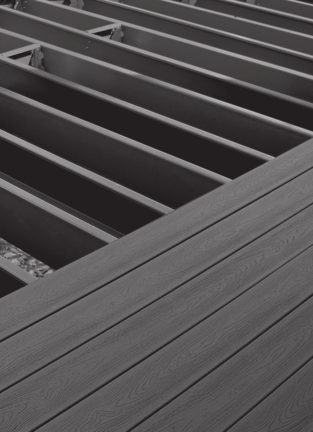
71 Maintenance warranty 7
72 TREX Elevations MAINTENANCE Corrosion is a naturally occurring phenomenon. However, with proper corrosion management, the life of Trex Elevations components can be extended well beyond the warranty period. Observation During construction, inspect all components for exposed steel, and cover the exposed area with Trex-approved touch-up paint in accordance with the Trex Product and Installation Guide. Covering exposed area with Trex-approved touch-up paint, such as Precision Color by Quest Industrial/Raabe Brown Textured, blends the blemishes into the same unique color of the components. First Maintenance First maintenance is defined as the physical inspection of components in search of corrosion. Atmospheric and environmental conditions can affect the longevity of Trex Elevations. Densities of air borne pollutants in certain atmospheres require adjustments in the maintenance and inspection schedules. Corrosion Management Sand any affected areas to twice the size of the corroded area with 80 grit sand paper. Reapply Trex-approved touch-up paint to the sanded area. Cleaning Deck Using cleaning recommendation per will not harm Trex Elevations. Be sure to rinse thoroughly on decking and framing. De-icing Use a non-saline based de-icing agent. Rinse off when first practical. Quest Industrial/Raabe is a registered trademark of Raabe Corporation. You should conduct first maintenance within 6 years (for residential) or 4 years (for commercial) after installation. If corrosion is identified, immediately begin corrosion management practices. Inspection Schedule After first maintenance, Trex Elevations components must be inspected for structural integrity every to 5 years (residential) or years (commercial). Integrity is inspected by tapping along the surface area of the components with a metal tool such as a screwdriver. If flaking of the exterior coat occurs or discrepancies of sound are heard, immediately begin corrosion management practices. maintenance 7

73 Warranty warranty 73
74 Trex ELEVATIONS Limited warranty Trex Company, Inc. ( Trex ) warrants to the original purchaser ( Purchaser ) that, for the period of time set forth in the following sentence, under normal use and service conditions, Trex Elevations steel deck framing components shall be free from material defects in workmanship and materials and will not become structurally unfit, which is defined as corrosion causing a perforation of the component. The term of such warranty shall be twenty-five (5) years from the date of original purchase for a residential application, and ten (0) years from the date of original purchase for a commercial application. If a defect occurs within the warranty period, Purchaser shall notify Trex in writing and, upon confirmation by an authorized Trex representative of the defect, Trex s sole responsibility shall be, at its option, to either replace the defective item or refund the portion of the purchase price paid by Purchaser for such defective item (not including the cost of its initial installation). For purposes of this warranty, a residential application shall refer to an installation of the Product on an individual residence, and a commercial application shall refer to any installation of the Product other than on an individual residence. Salt Water Applications: Trex Elevations may not be installed within 3,000 feet of any body of salt water due to increased risk of corrosion. Any such installation shall void this limited warranty. Other Water Applications: Trex Elevations may not be installed under the surface or within the splash zone of any body of fresh water due to increased risk of corrosion. Any such installation shall void this limited warranty. THIS LIMITED WARRANTY SHALL NOT COVER AND TREX SHALL NOT BE RESPONSIBLE FOR COSTS AND EXPENSES INCURRED WITH RESPECT TO THE REMOVAL OF DEFECTIVE TREX PRODUCTS OR THE INSTALLATION OF REPLACEMENT MATERIALS, INCLUDING BUT NOT LIMITED TO LABOR AND FREIGHT. With respect to a residential application, this warranty may be transferred one () time, within the five (5) year period beginning from the date of original purchase by the Purchaser, to a subsequent buyer of the property upon which the Trex products were originally installed. With respect to a commercial application, this warranty is freely transferable to subsequent buyers of the property upon which the Trex products were originally installed. To make a claim under this limited warranty, Purchaser, or the transferee, shall send to Trex, within the warranty period referred to above, a description of the claimed defect and proof of purchase, to the following address: Trex Company, Inc. Customer Relations 60 Exeter Drive Winchester, VA Trex does not warrant against and is not responsible for any condition attributable to: () defects caused by improper installation or decay caused by fasteners; () use of Trex products beyond normal use or service conditions, or in an application not recommended by Trex s guidelines and local building codes; (3) corrosion caused by factors other than environmental or atmospheric processes; (4) failure to strictly abide by Trex Elevations standard maintenance practices, as described below; (5) movement, distortion, collapse or settling of the ground; (6) any act of God (such as flooding, hurricane, earthquake, lightning, etc.); (7) improper handling, storage, abuse or neglect of Trex Elevations products by Purchaser, the transferee or third parties; or (8) ordinary wear and tear. No person or entity is authorized by Trex to make and Trex shall not be bound by any statement or representation as to the quality or performance of Trex products other than as contained in this warranty. This warranty may not be altered or amended except in a written instrument signed by Trex and Purchaser. warranty UNDER NO CIRCUMSTANCES WILL TREX BE LIABLE FOR SPECIAL, INCIDENTAL OR CONSEQUENTIAL DAMAGES, WHETHER SUCH DAMAGES ARE SOUGHT IN CONTRACT, IN TORT (INCLUDING BUT NOT LIMITED TO NEGLIGENCE AND STRICT LIABILITY) OR OTHERWISE, AND TREX S LIABILITY WITH RESPECT TO DEFECTIVE TREX ELEVATIONS PRODUCTS SHALL IN NO EVENT EXCEED THE REPLACEMENT OF SUCH PRODUCTS OR REFUND OF THE PURCHASE PRICE, AS DESCRIBED ABOVE. Some States or Provinces do not allow the exclusion or limitation of incidental or consequential damages, so the above limitation or exclusion may not apply to you. This warranty gives you specific legal rights, and you may also have other rights that vary from State to State or Province to Province. 74
75 Trex Elevations Maintenance Requirements:. Observation: During construction, inspect all components for exposed steel, and cover the exposed area with Trex approved touch up paint in accordance with the Trex Product and Installation Guide. (Trex does not warrant touch up paint due to application variability.) Covering exposed areas with Trex approved touch up paint blends the blemishes into the same unique color of the components.. First Maintenance: Defined as the physical inspection of components in search of corrosion. Atmospheric and environmental conditions can affect the longevity of Trex Elevations. Densities of air borne pollutants in certain atmospheres require adjustments in the maintenance and inspection schedules. You should conduct first maintenance within six (6) years after installation for a residential application and four (4) years after installation for a commercial application. If corrosion is identified, immediately begin corrosion management practices. 3. Inspection Schedule: After first maintenance, Trex Elevations components must be inspected for structural integrity every two () to five (5) years for a residential application and every two () years for a commercial application. Integrity is inspected by tapping along the surface area of the components with a metal tool such as a screwdriver. If flaking of the exterior coat occurs or discrepancies of sound are heard, immediately begin corrosion management practices. 4. Corrosion Management: Sand any affected areas to twice the size of the corroded area with 80 grit sand paper. Reapply Trex approved touch up paint to the sanded area. This warranty shall only be applicable and enforceable in the United States of America, Canada and Mexico. Copyright 03 Trex Company, Inc. warranty 75
76 NOTES warranty 76
77 NOTES warranty 77
78 78 NOTES

79 PRESSURE-TREATED LUMBER No warping, rotting or splitting Superior flatness & aesthetics Earth-friendly, recyclable material Termite proof Non-combustible fire rating Free of harmful chemicals

80 Steel joists and beams install just like wood beneath our Transcend decking. FIND US ON Visit trex.com or call -800-BUY-TREX 03 Trex Company, Inc. All rights reserved. Trex, the Trex logo, Trex Elevations, TrexTrim, Trex Deck Lighting and Trex Transcend are either federally registered trademarks, trademarks or trade dress of Trex Company, Inc., Winchester, Virginia. 083 XDLITINST03