Originally Issued: 08/31/2008 Revised: 10/05/2018 Valid Through: 08/31/2019
|
|
|
- Oswald Casey
- 5 years ago
- Views:
Transcription
1 EVALUATION SUBJECT: SIMPSON STRONG-TIE ANGLES, CLIPS, AND TIES REPORT HOLDER: Simpson Strong-Tie Company Inc West Las Positas Boulevard Pleasanton, California (800) CSI Division: 06 Wood, Plastics and Composites CSI Section: Wood, Plastic, and Composite Fastenings 1.0 SCOPE OF EVALUATION 1.1 Compliance to the following codes & regulations: 2015, 2012, 2009, and 2006 International Building Code (IBC) 2015, 2012, 2009, and 2006 International Residential Code (IRC) 2017 City of Los Angeles Building Code (LABC) attached Supplement 2017 City of Los Angeles Residential Code (LARC) attached Supplement 1.2 Evaluated in accordance with: IAPMO UES Evaluation Criteria for Joist Hangers and Miscellaneous Connectors (EC ) 1.3 Properties assessed: Structural 2.0 PRODUCT USE Simpson Strong-Tie structural angles, clips and ties are used as wood framing anchors and mechanical fastenings in accordance with Section of the 2015 IBC and of the 2012, 2009, and 2006 IBC. The products may be used in structures regulated under the IRC when an engineered design is submitted in accordance with Section R of the IRC. 3.0 PRODUCT DESCRIPTION 3.1 Product information A Series Angles: The A series angles transfer shear loads between wood members and are formed from No. 18 gage steel. Table 1 of this report provides model numbers, dimensions, fastener schedules, allowable loads, and installation details A34 and A35 Framing Angles: The A34 and A35 framing angles connect wood framing members and are fabricated from No.18 gage steel. The connectors have cutouts on each leg and a prong to aid in installation. The A35 angle has slots and bend lines to permit field adjustments of the legs for two- and three-way tied connections and shall be bent one-time only. Table 2 and Figure 2 of this report provide model numbers, dimensions, fastener schedules, allowable loads, and installation details FC Series Framing Clips: The FC series framing clips transfer shear loads between wood members and are formed from No. 16 gage steel. Table 3 and Figure 3 of this report provide model numbers, dimensions, fastener schedules, allowable loads, and installation details GA Series Gusset Angles: The GA series gusset angles connect wood framing members and are formed from No. 18 gage steel. Table 4 and Figure 4 of this report contain model numbers, dimensions, fastener schedules, allowable loads, and installation details H2A, H2.5T, H8, H10A-2, H10S, H14 and HGA10 Hurricane Ties: The hurricane ties connect wood rafters or trusses to wood wall plates or studs. The H2A, H2.5T, H8, H10A-2, H10S, and H14 are formed from No. 18 gage steel, and the HGA10 is formed from No. 14 gage steel. Table 5 and Figure 5 of this report contain model numbers, dimensions, fastener schedules, allowable loads, and installation details HH Series Header Hangers: The HH series header hangers transfer wind uplift and lateral loads between wood roof and wall members and are formed from No. 16 gage steel. Table 6 and Figure 6 of this report provide model numbers, dimensions, fastener schedules, allowable loads, and installation details L Series Reinforcing Angles: The L series reinforcing angles connect wood framing members and are formed from No. 16 gage steel. Table 7 and Figure 7 of this report describe model numbers, dimensions, fastener schedules, allowable loads, and installation details LCE4 Post Cap: The LCE4 post cap transfers uplift and lateral forces from a wood beam to a wood post and is formed from No. 20 gage steel. Table 8 and Figure 8 of this report describe model numbers, dimensions, fastener schedules, allowable loads, and installation details LS Series Skewable Angles: The LS series skewable angles transfer loads between wood framing members and are formed from No. 18 gage steel. The angles are designed to allow field skewing from 0 to 135 degrees and shall be bent one time only. Table 9 and Figure 9 of this report The product described in this Uniform Evaluation Service (UES) Report has been evaluated as an alternative material, design or method of construction in order to satisfy and comply with the intent of the provisions of the code, as noted in this report, and for at least equivalence to that prescribed in the code in quality, strength, effectiveness, fire resistance, durability and safely, as applicable, in accordance with IBC Section This report shall only be reproduced in its entirety. Copyright 2018 by International Association of Plumbing and Mechanical Officials. All rights reserved. Printed in the United States. Ph: IESRPT Fax: web: East Philadelphia Street, Ontario, California USA Page 1 of 19
2 contain model numbers, dimensions, fastener schedules, allowable loads, and installation details LTP4 and LTP5 Lateral Tie Plates: The LTP4 and LTP5 lateral tie plates transfer shear loads from the wood top plate to wood rim joist or blocking members and is formed from No. 20 gage steel. Table 10 and Figure 10 of this report provide model numbers, dimensions, fastener schedules, allowable loads, and installation details RBC and RBCP Roof Boundary Clips: The RBC/RBCP roof boundary clips transfer loads between the roof diaphragm perimeter blocking and wall top plates and are formed from No. 20 gage steel. The clips may be fieldbent to desired angle one time only. Table 11 and Figure 11 of this report contain model numbers, dimensions, fastener schedules, allowable loads, and installation details TJC Jack Truss Connectors: The TJC Jack Truss Connectors are field skewable connectors that transfer loads from jack trusses, joists, rafters and blocking members to supporting members, and are formed from No. 16 gage steel. Table 12 and Figure 12 of this report describe model numbers, dimensions, fastener schedules, allowable loads, and installation details Z Series Panel Stiffener Clips: The Z2 and Z4, Z44 panel stiffener clips are formed from No. 20 and No. 12 gage steel, respectively. The Z clips are used to support nominally 2-by-4 or 2-by-6 wood blocking between joists or trusses that provide solid backing for ceiling panel material. Table 13 and Figure 13 of this report provide model numbers, dimensions, fastener schedules, allowable loads, and installation details FWANZ Foundation Wall Angles: The FWANZ foundation wall angles are used to attach the foundation or basement walls to the floor system to resist out-of-plane loads imposed by soil pressure. Each angle fastens to the wood rim-board and wood mudsill with nails. The FWANZ is formed from No. 14 gage steel. Table 14 and Figure 14 of this report provide model numbers, dimensions, fastener schedule, allowable loads, and installation details. 3.2 Materials CORRESPONDING BASE CONNECTOR METAL THICKNESS STEEL GAGE (inches) No No No No No For SI: 1 inch = 25.4 mm Steel: The FWANZ, H2A, H2.5T, H8, H14, LCE4, Page 2 of 19 LTP5, RBC, and RBCP connectors described in this report are manufactured from galvanized steel complying with ASTM A653, Grade 40, SS designation with a minimum yield strength of 40,000 psi (227 MPa) and a minimum ultimate tensile strength of 55,000 psi (358 MPa). All other connectors described in this report are manufactured from galvanized steel complying with ASTM A653, Grade 33, SS designation with a minimum yield strength of 33,000 psi (227 MPa) and a minimum ultimate tensile strength of 45,000 psi (310 MPa). The connectors have a minimum G90 zinc coating designation complying with ASTM A653. Some models also are available with a G185 zinc coating designation in accordance with ASTM A653 (denoted by model numbers ending in the letter Z). Some models are available with a batch hot-dipped galvanized coating in accordance with ASTM A123, with a minimum specified coating weight of 2.0 ounces of zinc per square foot of surface area (600 g/m 2 ), total for both sides (denoted by model numbers ending with the letters HDG). Model numbers in this report do not list the Z or HDG ending, but the information shown applies. The holder of this report (Simpson Strong-Tie) or the lumber treater shall be contacted for recommendations on minimum corrosion resistance of steel connectors in contact with specific proprietary preservative-treated or fire-retardanttreated lumber Wood: Wood members with which the connectors are used shall be either sawn lumber or engineered lumber having a minimum specific gravity of 0.50 (minimum equivalent specific gravity of 0.50 for engineered lumber) and having a maximum moisture content of 19 percent (16 percent for engineered lumber), except as noted in Section 4.1 of this report. The thickness (depth) of the wood main member shall be equal to or greater than the length of the fasteners specified in the tables in this report, unless the reduced penetration effect on the load calculation per the applicable ANSI/AWC National Design Specification for Wood Construction and its Supplement (NDS) is taken into account, or as required by wood member design, whichever is greater Fasteners: Common nails shall comply with ASTM F1667 when used with connectors in this report and shall have the following minimum fastener dimensions and bending yield strengths (F yb): FASTENER SHANK DIAMETER (inches) FASTENER LENGTH (inches) Fyb (psi) 8d x 1½ ½ 100,000 8d ½ 100,000 10d x 1½ ½ 90,000 10d ,000 16d ½ 90,000 For SI: 1 inch = 25.4 mm, 1 psi = kpa.
3 Fasteners used in contact with fire-retardant-treated or preservative-treated lumber shall comply with Section of the 2015 IBC; Section of the 2012, 2009, or 2006 IBC; 2015, 2012 or 2009 IRC Section R317.3, or 2006 IRC Section R319.3, as applicable. The report holder or lumber treater shall be contacted for recommendations on minimum corrosion resistance and connection capacities of fasteners used with the specific proprietary preservative-treated or fire-retardant-treated lumber. SDS wood screw fasteners described in Tables 5 and 12 of this report shall be Simpson Strong-Tie SDS wood screws recognized in ICC-ES ESR DESIGN AND INSTALLATION 4.1 Design The tabulated connector loads shown in this report are for allowable stress design and include the load duration factor, C D, corresponding with the applicable loads in accordance with the ANSI/AWC National Design Specification for Wood Construction and its supplement (NDS). Further load duration increases are not permitted other than those shown. Tabulated allowable loads apply to products connected to wood used where sustained temperatures are 100 F (37.8 C) or less and under dry conditions. The allowable loads shall be adjusted by the wet service factor, C M, specified in the NDS for dowel-type fasteners, when products are installed to wood having a moisture content greater than 19 percent (16 percent for engineered wood products), or where wet service is expected. The allowable loads in this report shall be adjusted by the temperature factor, C t, specified in the NDS when connectors are installed in wood that will experience sustained exposure to temperatures exceeding 100 F (37.8 C). 4.2 Installation Installation of the connectors shown in this report shall be in accordance with the manufacturer s published installation instructions and this evaluation report. If there is a conflict between this report and the manufacturer s published installation instructions, the more restrictive prevails. 4.3 Special Inspection Periodic special inspection shall be conducted in accordance with 2015 IBC Sections and , 2012 IBC Section , 2009 IBC Section 1706, or 2006 IBC Section 1704, as applicable, when the product series are components within the main wind-force-resisting system of structures constructed in areas listed in 2015 IBC Section , 2012 IBC Section , 2009 IBC Section and Section for the 2006 IBC. Special inspection requirements do not apply to structures, or portions thereof, that qualify for exception under 2015 IBC Sections or , 2012 IBC Sections , , or , 2009 IBC Sections , , or and 2006 IBC Sections or Periodic special inspection shall be conducted in accordance with the applicable subsections of Sections and of the 2015 IBC, Section of the 2012 IBC and Section 1707 of the 2009 and 2006 IBC when the product series are components within the seismic-forceresisting system of structures constructed in Seismic Design Category C, D, E or F. Special inspection requirements do not apply to structures, or portions thereof, that qualify for exception under 2015 IBC Sections or , 2012 IBC Sections or , 2009 IBC Sections , or or 2006 IBC Sections or For installations under the IRC, special inspection is not normally required. However, for an engineered design where calculations are required to be signed by a registered design professional, periodic special inspection requirements and exemptions are as stated in Sections and of this report as applicable for installations under the IRC. 5.0 LIMITATIONS The Simpson Strong-Tie products described in this report are in compliance with, or are acceptable alternatives to what is specified in those codes listed in Section 1.0 of this report subject to the following conditions: 5.1 The connectors shall be manufactured, identified and installed in accordance with the manufacturer s published installation instructions and this report. A copy of the instructions shall be available at the jobsite continuously during installation. If there is a conflict between this report and the manufacturer s published installation instructions, the more restrictive prevails. 5.2 Where applicable, adjustment factors noted in Section 4.1 of this report and the applicable codes shall be considered. 5.3 Connected wood members and fasteners shall comply, respectively, with Sections and of this report. 5.4 Use of connectors with fire-retardant-treated or preservative-treated lumber shall be in accordance with Section of this report. Use of fasteners with fireretardant-treated or preservative-treated lumber shall be in accordance with Section of this report. 6.0 SUBSTANTIATING DATA Data in accordance with IAPMO UES Evaluation Criteria for the Testing and Analysis of Joist Hangers and Page 3 of 19
4 Miscellaneous Connectors (EC ), inclusive of tests and calculations. 7.0 IDENTIFICATION A label shall be affixed on at least one of the following: product, packaging, installation instructions or descriptive literature. The label shall include the company name or trademark, model number, and the IAPMO Uniform ES Mark of Conformity the name of the inspection agency (when applicable) and the Evaluation Report Number (ER- 112) to identify the products recognized in this report. A diestamp label may also substitute for the label. Either Mark of Conformity may be used as shown below: or IAPMO UES ER-112 Brian Gerber, P.E., S.E. Vice President, Technical Operations Uniform Evaluation Service Richard Beck, PE, CBO, MCP Vice President, Uniform Evaluation Service GP Russ Chaney CEO, The IAPMO Group For additional information about this evaluation report please visit or at info@uniform-es.org Page 4 of 19
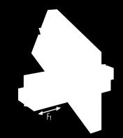
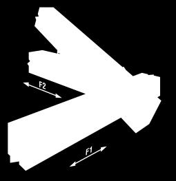
 L W 1 W 2 FASTENERS Supporting Member (Base) Supported Member (Post) ALLOWABLE LOADS 2,3,4,5 (lbs) F 1 where C D = F 2 where C D = 1.0 1.15 1.25 1.")

5 TABLE 1: ALLOWABLE LOADS FOR THE A ANGLES MODEL NO. ANGLE DIMENSIONS 1 (in) L W 1 W 2 FASTENERS Supporting Member (Base) Supported Member (Post) ALLOWABLE LOADS 2,3,4,5 (lbs) F 1 where C D = F 2 where C D = A / /2 2-10d x 1½ 2-10d x 1½ A / /2 4-10d x 1½ 4-10d x 1½ A / d 4-10d A /2 4 9 / /8 4-10d 4-10d Figure 1 of this report details definitions of angle dimension nomenclature (L, W1, W2) and allowable load directions (F1 and F2). 2. Tabulated allowable loads shall be selected based on duration of load as permitted by the applicable NDS edition. 3. F1 and F2 loads shall not be combined. 4. The F1 allowable loads are for one connector. When angles are installed on each side of wood member, the minimum member thickness shall be 3 inches. 5. The F2 allowable loads apply only when the connectors are used in pairs. 6. Allowable loads have been increased for wind or earthquake loading. No further increase is allowed. Figure 1 A21 and A23 Angles Page 5 of 19

 Joist Header/Plate OF LOAD 3 CD=1.0 CD=1.")


6 MODEL NO. TABLE 2: ALLOWABLE LOADS FOR THE A34 / A35 FRAMING ANGLES FASTENERS DIRECTION ALLOWABLE LOADS 1,2,4 (lbs) Joist Header/Plate OF LOAD 3 CD=1.0 CD=1.15 CD=1.25 CD=1.6 A34 4-8dx1½ 4-8dx1½ F dx1½ 4-8dx1½ F dx1½ 6-8dx1½ A dx1½ 6-8dx1½ C dx1½ 6-8dx1½ E A35 6-8dx1½ 6-8dx1½ A dx1½ 6-8dx1½ C dx1½ 6-8dx1½ D dx1½ 6-8dx1½ F dx1½ 6-8dx1½ F Tabulated allowable loads shall be selected based on duration of load as permitted by the applicable NDS edition. 2. Allowable loads are for one angle. When anchors are installed on each side of the joist, the minimum joist thickness is 3 inches. 3. Connectors are required on both sides of joist to achieve F2 loads in both directions. 4. Some illustrations below show connections that could cause cross-grain tension or bending of the wood during loading if not reinforced sufficiently. In this case, mechanical reinforcement should be considered. Figure 2 A34 and A35 Framing Angles Page 6 of 19
 (in) FASTENERS")


.")


7 MODEL NO. TABLE 3: ALLOWABLE LOADS FOR THE FC FRAMING CLIPS CONNECTOR WIDTH (W) (in) FASTENERS ALLOWABLE DOWNLOAD, F1 1,2 (lbs.) CD=1.0 CD=1.15 CD=1.25 FC4 3 9 / d FC6 5 1 / d 1,005 1,140 1, Tabulated allowable loads shall be selected based on duration of load as permitted by the applicable NDS edition. 2. Minimum thickness of the supporting member (post) shall be 2 1 /2 inches to achieve the tabulated load value (similar to Figure 6 of this report). FC Connector Dimensions Typical FC Connector Installation MODEL NO. ANGLE LENGTH (L) (inches) Figure 3- FC Framing Clips TABLE 4: ALLOWABLE LOADS FOR GA GUSSET ANGLES FASTENERS ALLOWABLE LOADS 1 (lbs) F 1 where C D = F 2 where C D = GA1 2 3 / d x 1 ½ GA2 3 1 / d x 1 ½ Tabulated allowable loads shall be selected based on duration of load as permitted by the applicable NDS edition. 2. Allowable loads have been increased using the tabulated value of CD for wind or earthquake loading. No further increase is allowed. 3. Connectors are required on both sides to achieve F2 loads in both directions. GA1 Typical GA Installation Figure 4 GA Gusset Angles Page 7 of 19
8 MODEL NO. TABLE 5: ALLOWABLE LOADS FOR H HURRICANE TIES ALLOWABLE LOADS FASTENERS 1,2,3,5,6 (lbs) Uplift 3 Lateral CD=1.6 To Rafter To Plates To Studs CD=1.6 F1 4 F2 H2A 5-8d x 1½ 2-8d x 1½ 5-8d x 1½ H2.5T 5-8d 5-8d H8 5 10d x 1 ½ 5 10d x 1 ½ H10A d x d x 3-1, H10S 8-8d x 1½ 8-8d x 1½ 8-8d 910 7,8, , H d x 1½ d - 1, d x 1½ d - 1, HGA10 4 SDS 1/4 x 1½ 4 SDS 1/4 x , SI: 1 inch = 25.4 mm, 1 lbs = 4.45 N 1. Allowable loads are for one anchor. A minimum rafter thickness of 2½ inches shall be used when framing anchors are installed on each side of the rafter and on the same side of the plate. Hurricane ties do not replace solid blocking. When installing on plated trusses (on the side opposite the truss plate) the ties shall not be fastened through the truss plate from behind. This may force the truss plate off of the truss and compromise truss performance. 2. Allowable simultaneous loads in more than one direction on a single connector shall be evaluated as follows: Design Uplift/Allowable Uplift + Design Lateral Parallel to Plate/Allowable Lateral Parallel to Plate + Design Lateral Perpendicular to Plate/Allowable Lateral Perpendicular to Plate < 1.0. The number of terms considered in the equation is dependent on the designer s method of calculating wind forces and the utilization of the connector in the structural system. 3. The loads have been increased for wind or earthquake loading using the tabulated value of CD with no further increase is allowed. Allowable loads shall be adjusted when other load durations govern. 4. Allowable loads in the F1 direction are not intended to replace diaphragm boundary members or prevent cross-grain bending of the truss or rafter members. 5. When cross-grain bending or cross-grain tension is present in the members, mechanical reinforcement of the wood members to resist such loads shall be considered. 6. Hurricane Ties are shown installed on the outside of the wall for clarity. Installation on the inside of the wall is acceptable. For a Continuous Load Path against uplift loads, connections in the same area (i.e. truss to plate connector and plate to stud connector) shall be on same side of the wall. 7. Allowable uplift load for the H2.5T and H10S with 8dX1½ fasteners is 420 lbs and 465 lbs, respectively. 8. H10S nails to plates are optional for uplift loads but required for lateral loads. 9. For H10S, the stud may be offset 1 inch maximum from center of rafter for reduced uplift and F1 load capacities of 890 lbs and 535 lbs, respectively. 10. HGA10 F2 value is for load acting toward the connector. For load away from the connector, F3 = 815 lbs. Page 8 of 19


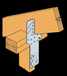


9 H2A H2.5T H8 H10A-2 H2A Typical Installation H2.5T Typical Installation H8 Typical Installation H10A-2 Typical Installation H10S HGA10 H H10S Typical Installation HGA10 Typical Installation H14 Typical Top Plate Installation H14 Typical Beam Installation Figure 5 H Hurricane Ties Page 9 of 19


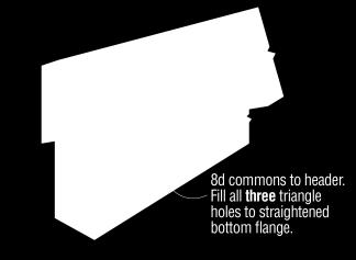
10 TABLE 6: ALLOWABLE LOADS FOR THE HH HEADER HANGERS MODEL NO. HANGER DIMENSIONS 1 (in) MIN. POST FASTENERS SIZE W H Stud Header ALLOWABLE LOADS 2 (lbs) F1 where CD = 4 F2 F3 F where CD = x 7-10dx1 1 /2 4-10dx1 1 / , HH4 3 1 / /16 Dbl 2x 7-16dx2 1 /2 4-16dx2 1 /2 1,005 1,140 1, x 9-16d 4-16d 1,295 1,470 1, x 10-10dx1 1 /2 6-10dx1 1 /2 1,215 1,375 1,480 1, HH6 5 1 /2 5 1 /8 Dbl 2x 10-16dx2 1 /2 6-16dx2 1 /2 1,440 1,630 1,760 1,045 1,605 3x 12-16d 6-16d 1,725 1,955 2, ,045 1, Figure 6 of this report describes definitions of dimension nomenclature (W and H). 2. Tabulated allowable loads shall be selected based on duration of load as permitted by the applicable NDS edition. 3. Allowable loads have been increased using the tabulated value of CD for wind or earthquake loading. No further increase is allowed. 4. Duration of load increase shall not exceed HH4 Hanger Dimensions Typical HH Installation Allowable Load Directions Figure 6 HH Header Hangers Page 10 of 19
 FASTENERS 5 ALLOWABLE LOADS 1,3,4 (lbs) F1 where CD = F2 where CD = (inches) 1.0 1.15 1.25 1.")


11 TABLE 7: ALLOWABLE LOADS FOR THE L REINFORCING ANGLES MODEL NO. ANGLE LENGTH (L) FASTENERS 5 ALLOWABLE LOADS 1,3,4 (lbs) F1 where CD = F2 where CD = (inches) L d x 1 ½ L d x 1 ½ L d x 1 ½ L d x 1 ½ Tabulated allowable loads shall be selected based on duration of load as permitted by the applicable NDS edition. 2. Allowable loads have been increased for wind or earthquake loading. No further increase is allowed. 3. Minimum member thickness shall be 1¾ inches to achieve the tabulated allowable load values. 4. Connectors are required on both sides to achieve F2 loads in both directions. 5. The L angle's wider leg shall be nailed into the joist to ensure tabulated loads and allow correct nailing. L Angle Typical L50 Installation and Allowable Load Directions Figure 7 L Reinforcing Angles Page 11 of 19


12 TABLE 8: ALLOWABLE LOADS FOR LCE4 POST CAP FASTENERS ALLOWABLE LOADS 1,2 (lbs) MODEL NO. Uplift 3 Lateral Beam Post CD=1.60 CD=1.60 LCE d 10-16d 1,665 1,230 LCE4 (Mitered Corner) 14-16d 10-16d SI: 1 inch = 25.4 mm, 1 lbs = 4.45 N 1. The loads have been increased using the tabulated value of CD for wind or earthquake loading, with no further increase allowed. Allowable loads shall be adjusted when other load durations govern. 2. Loads apply only when used in pairs. Loads in table above are for each connector. 3. Uplift loads do not apply to splice conditions. LCE4 LCE4 (Mitered Corner) Figure 8 LCE4 Post Cap Page 12 of 19
 TABLE 9: ALLOWABLE LOADS FOR LS SKEWABLE ANGLES Carried Member FASTENERS")


13 MODEL NO. L (inches) TABLE 9: ALLOWABLE LOADS FOR LS SKEWABLE ANGLES Carried Member FASTENERS Carrying Member ALLOWABLE LOADS 1,2,3 (lbs) CD=1.0 CD=1.15 CD=1.25 CD=1.6 LS30 LS50 LS70 LS90 3 ⅜ 4 ⅞ 6 ⅜ 7 ⅞ 3-10d x 1½ 3-10d x 1½ d 3-10d d x 1½ 4-10d x 1½ d 4-10d d x 1½ 5-10d x 1½ d 5-10d d x 1½ 6-10d x 1½ d 6-10d , Tabulated allowable load capacities shall be selected based on duration of load as permitted by the applicable NDS edition. 2. Figure 9 of this report indicates load directions. 3. Joist shall be constrained against rotation (for example, with solid blocking) when using a single LS per connection. LS U.S. Patent 4,230,416 LS Installed LS Bend Angles Figure 9 LS Skewable Angles Page 13 of 19

 CD=1.")


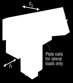
14 TABLE 10: ALLOWABLE LOADS FOR LTP4 AND LTP5 LATERAL TIE PLATES MODEL NO. LTP4 CONNECTOR CONFIGURATION FASTENERS Rim Board Plates ALLOWABLE LATERAL LOADS 1,3 (lbs) CD=1.6 G 6-8d x 1 ½ 6-8d x 1 ½ 625 H 6-8d x 1 ½ 6-8d x 1 ½ 525 LTP5 2 G 6-8d x 1 ½ 6-8d x 1 ½ 565 H 6-8d x 1 ½ 6-8d x 1 ½ The loads have been increased using the tabulated value of CD for wind or earthquake loading with no further increase allowed. Allowable loads shall be adjusted when other load durations govern. 2. The LTP5 may be installed over wood structural panel sheathing no greater than inch thick. 3. Some illustrations show connections that may cause cross-grain tension or bending of the wood during loading if not reinforced sufficiently. In this case, mechanical reinforcement should be considered. LTP5 LTP5 Typical Installations LTP4 LTP4 Typical Installations Figure 10 LTP4 and LTP5 Lateral Tie Plates Page 14 of 19


15 TABLE 11: ALLOWABLE LOADS FOR RBC/RBCP ROOF BOUNDARY CLIPS MODEL NO. RBC CONNECTION TYPE BEND ANGLE 4,5 Inside 45 to 90 Outside FASTENERS Plate Blocking ALLOWABLE LATERAL LOADS 1,2,3 (lbs) CD= to dx1 ½ 6-10dx1 ½ to The loads have been increased using the tabulated value of CD for wind or earthquake loading with no further increase allowed. Allowable loads shall be adjusted when other load durations govern. 2. Allowable loads are for one clip attached to blocking minimum 1½ inch thick. 3. RBCP replaces blocking fasteners with prongs. All load values are identical. Bend holes shall be aligned along lower edge of block as shown in Figure 11 of this report. All prongs in the RBCP shall be pressed (not hammered) into the block such that there is no more than a 1/32 inch gap between the face of the block and the bottom surface of the RBCP. RBCP prongs shall be installed in clear wood (no knots, etc.). 4. RBC/RBCP is shipped flat. Bending angle is measured from initial flat orientation. For inside installation, the bend angle = 90 - roof slope. For outside installation, the bend angle = roof slope. 5. RBCP bend holes shall be aligned along lower edge of block as shown in Figure 11 of this report. RBC U.S. Patents 7,293,390 7,549,262 RBC Inside Installation (RBCP Similar) RBC Outside Installation RBCP RBCP Outside Installation Figure 11 RBC and RBCP Roof Boundary Clips Page 15 of 19
 TJC37 TJC57 Carrying Member Carried Member 0 Skew 1 to 60 Skew 61 to 67.")


16 TABLE 12: ALLOWABLE LOADS FOR TJC TRUSS JACK CONNECTOR MODEL NO. FASTENERS ALLOWABLE LOADS 1,2,3,4 Where CD=1.0; CD=1.15; CD=1.25; CD=1.6 (lbs.) TJC37 TJC57 Carrying Member Carried Member 0 Skew 1 to 60 Skew 61 to 67.5 Skew 4-8dx1 ½ 4-8dx1 ½ dx1 ½ 6-8dx1 ½ dx1 ½ 12-8dx1 ½ SD SD9112 1, No load duration increase allowed. 2. Allowable loads are for vertical direction (uplift or download). 3. TJC37 and TJC57 require single-ply carried members with minimum 2x4 and 2x6 chord members, respectively. 4. Back-to-back installation on a single-ply girder/hip member is outside the scope of this report. To reduce the potential for splitting, the TJC shall be installed with a minimum 3/16 inch edge distance on the chord members. TJC Bend Angles TJC Typical Installation TJC37 TJC57 Figure 12 TJC Truss Jack Connector Page 16 of 19
 Z2 2 5 /16 1 1 /2 1 3 /8 1 3 /8 2-10d x 1 1 /2 2-10d x 1 1 /2 420 Z4 1 1 /2 3 1 /2 2 1 /8 1 3 /4 1-16d 1-16d 420 Z44 2 1 /2 3 1 /2 2 1 3 /8 2-16d 2-16d 775 1.")

17 MODEL NO. TABLE 13: ALLOWABLE LOADS FOR Z PANEL STIFFENER CLIPS CLIP DIMENSIONS 1 (in) FASTENERS W H B TF Top Seat ALLOWABLE DOWNLOAD 2,3 Where CD=1.0 CD=1.15 CD=1.25 CD=1.6 (lbs.) Z2 2 5 / /2 1 3 /8 1 3 /8 2-10d x 1 1 /2 2-10d x 1 1 /2 420 Z4 1 1 /2 3 1 /2 2 1 /8 1 3 /4 1-16d 1-16d 420 Z /2 3 1 / /8 2-16d 2-16d Figure 13 of this report provides definitions of clip dimension nomenclature (W, H, B, TF). 2. No load duration increase permitted. 3. Compression perpendicular-to-grain capacity for the joists bearing on the clips shall be verified in accordance with the applicable NDS edition and shall not exceed the allowable loads noted in the table. Z Typical Z Clip Installation Figure 13 Z Panel Stiffener Clips Page 17 of 19
 10d x 1½ (5) 10d x 1½ 1⅛\" OSB 815 815 815 1¾\" I-Joist 940 1,045 1,070 1¼\" LSL 940 1,045 1,105 2x DF/SP 940 1,045 1,390 FWANZ 1¾\" LVL 940 1,045 1,245 1\"")


18 TABLE 14: ALLOWABLE LOADS FOR FWANZ FOUNDATION WALL ANGLES Model No. Sill Plate Fastener Sill Plate Rim Board Rim Board Material Allowable F2 Load CD = 0.90 CD = 1.00 CD = " OSB x4, 3x4, 2-2x4, 4x4 (8) 10d x 1½ (5) 10d x 1½ 1⅛" OSB ¾" I-Joist 940 1,045 1,070 1¼" LSL 940 1,045 1,105 2x DF/SP 940 1,045 1,390 FWANZ 1¾" LVL 940 1,045 1,245 1" OSB x6, 3x6, 2-2x6, 4x6 (11) 10d x 1½ (5) 10d x 1½ 1⅛" OSB ¾" I-Joist ¼" LSL 1,025 1,025 1,025 2x DF/SP 1,295 1,440 1,445 1¾" LVL 1,295 1,385 1, Tabulated allowable loads shall be selected based on duration of load as permitted by the applicable NDS edition. 2. FWANZ lateral F1 load is equal to 260 lbs. No further increase in load permitted. 3. For simultaneous F1 and F2 loads, the connector shall be evaluated as follows: Design Lateral Parallel to Plate/Allowable Lateral Parallel to Plate + Design Lateral Perpendicular to Plate/Allowable Lateral Perpendicular to Plate 1.0. The number of terms in the equation is dependent on the utilization of the connector in the structural system. 4. For joist/blocking spacing up to 16 inches on center FWANZ shall be centered between joists/blocking. For joist/blocking spacing greater than 16 inches on center but not exceeding 48 inches on center. The FWANZ shall be located within 4 inches of the adjacent joist/blocking. 5. Splice joint not permitted on rim board in same bay as FWANZ unless blocking is placed on both sides of the splice joint. 6. When floor joists are parallel to the rimboard, the structural design professional shall ensure proper load transfer from rimboard into the diaphragm. 7. When I-joist rim material is used, backer blocks shall be used and installed according to the I-Joist manufacturer's instructions. FWANZ Typical Installation and Allowable Load Direction Figure 14 FWANZ Foundation Wall Angles Page 18 of 19
19 CITY OF LOS ANGELES SUPPLEMENT SIMPSON STRONG-TIE ANGLES, CLIPS, AND TIES REPORT HOLDER: Simpson Strong-Tie Company Inc West Las Positas Boulevard Pleasanton, California (800) Calculations verifying compliance with the Simpson Strong-Tie structural angles, clips, and ties shall be submitted to the plan check engineer at the time of permit application. The calculations shall be prepared by a Civil or Structural Engineer registered in the State of California. For additional information about this evaluation report please visit or us at info@uniform-es.org CSI Division: 06 Wood, Plastics and Composites CSI Section: Wood, Plastic, and Composite Fastenings 1.0 RECOGNITION Simpson Strong-Tie structural angles, clips, and ties described in ER-112 and this supplemental report have been evaluated for use as wood framing anchors and mechanical fastenings. Simpson Strong-Tie structural angles, clips, and ties have been evaluated for structural performance properties, subject to the requirements in ER-112 and this supplemental report. Simpson Strong-Tie structural angles, clips and ties were evaluated for compliance with the following codes and regulations: 2017 City of Los Angeles Building Code (LABC) 2017 City of Los Angeles Residential Code (LARC) 2.0 LIMITATIONS Use of the Simpson Strong-Tie structural angles, clips, and ties recognized in this supplement are subject to the following limitations in addition to the limitations shown in the master ER-112: 2.1 Simpson Strong-Tie structural angles, clips, and ties shall be manufactured, identified and installed in accordance with ER-112 and the manufacturer s published installation instructions. A copy of the installation instructions shall be available at the job site continuously during installation. If there is a conflict between this report and the manufacturer s published installation instructions, the more restrictive prevails. Page 19 of 19