Safety Concerns with New
|
|
|
- Ashlie Heath
- 5 years ago
- Views:
Transcription
1 Safety Concerns with New PV Polymeric Materials Crystal Vanderpan Underwriters Laboratories Inc. October 17, 2010 Copyright Underwriters Laboratories Inc. All rights reserved. No portion of this material may be reprinted in any form without the express written permission of Underwriters Laboratories Inc. or as otherwise provided in writing.
2 Crystal Vanderpan Principal Engineer for PV Materials and Printed Circuit Technologies Joined UL in 1995 Technical rep on UL STPs for Rigid and Flex PWB Standards Subcommittee chairman ASTM D09.07 Electrical and Electronic Insulating Materials Active in IEC TC82, WG2 PV Modules and Materials B.S. Chemical Engineer/Materials Science, UC Davis p/2
3 Getting New PV Materials to Market What this session will cover Changing PV Market Safety Risks Performance vs Safety Evaluations PV Material Standards Work PV Materials Pre-selection Process p/3
4 PV Growth in US Cumulative US Grid-tied PV Installations Data Source: Interstate Renewable Energy Council Review 2009 p/4
5 PV Module Landscape is Changing g PV modules produced between 1990 and 2005 Share similar constructions, materials, and manufacturing process Traditional PV module recipe Developed with many years of research and testing Good track record p/5
6 Past and Future PV Performance Past performance can t predict the future New PV module configurations and applications New manufacturers with little PV module experience New manufacturing processes New construction techniques p/6
7 New Construction Techniques for PV New PV materials Thermoplastics, encapsulants and adhesives with low softening / melt temps Conductive adhesives to replace solder Polymeric mounting systems p/7
8 Thermoplastic Material Concerns Transition away from crosslinked EVA More thermoplastic encapsulants and mounting materials in the PV construction ti Thermoplastics flow or creep over time when exposed to high operating temperatures Some new materials have melt temperatures less than 100C p/8


9 PV Module Temperature Testing Worst case module temperatures are not addressed and can be well above 90C due to High ambients High irradiance Shading conditions Temperature tests are normalized to 40C Chamber cycling is done at 90C max p/9
10 PV Polymeric Material Creep or Flow Any movement can create problems! Risk of shock, fire or mechanical hazards Electrical connections Short or open circuits it Displacement of electrical conductors or components Loss of contact pressure Mounting Delamination Loss of mechanical integrity Falling modules or falling glass p/10
11 PV Evaluation Challenge! Existing evaluation programs are not sufficient i Do not address all safety concerns as demonstrated t d by increased product testing ti failures New generation of PV modules New components New materials p/11


12 Why Safety Testing? 8 years operation in Arizona Passed original qualification tests p/12
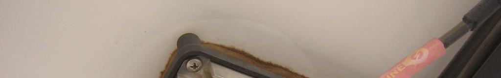


13 Backsheet Delamination p/13
14 p/14
15 p/15


16 Hazard-Based Engineering g Approach Analyze the installation Location and intended use Attachment systems, wiring systems, hazards Analyze the product Materials, construction, hazards p/16
17 Hazard-Based Engineering g Approach Utilize existing standards & knowledge Standards d may exist for similar il products / situations ti Code requirements may exist Test to provide confidence Use UL and/or IEC for PV modules Use other standards to address incidental hazards p/17
18 Who is UL? Underwriters Laboratories Inc (UL) is an independent, not-for-profit safety testing and certification organization Founded in 1894, UL has earned a reputation as a global leader in product safety standards development, testing and certification Today UL founded AIMCAL founded IEC IEC IEC UL 94 UL 746A UL 1703 UL 5703 p/18
19 Certification and Product Development Cycle Performance Certification IEC or One time evaluation, no Follow Up test If no Follow Up testing: Modules, components and materials may vary and invalidate performance certification Pre-design Design Prototype Production Distribution Field Products Safety Consulting Certification IEC or UL 1703 Prelim Investigation Certification Manufacture Follow-up Inspection and Testing Product failure Field Reports p/19
20 IEC PV Module Safety Scope and Objective Describes the fundamental construction ti requirements for photovoltaic (PV) modules To provide safe electrical and mechanical operation during their expected lifetime Specific topics assess the prevention of electrical shock, fire hazards, and personal injury due to mechanical and environmental stresses p/20
21 UL 1703 Safety Standard for PV Modules Evaluate electrical shock hazards Product and application Evaluate fire resistance & propagation hazards Product and application Verify evaluation through testing Provide subsequent Follow-Up inspection of manufacturing locations p/21
22 UL 5703 PV Backsheet Materials Outline of Investigation Scope Evaluation of PV materials including backsheet and encapsulant materials Long term temperature rating evaluations UL746A Short term property characterization Frontsheet and conductive adhesive requirements to be added Provide subsequent Follow-Up inspection of manufacturing locations p/22
23 Applications Enclosure Support of Live Parts Outer Enclosure Barrier / Liner Junction Boxes Thermal Index p/23
24 Material Property Requirements Short Term (depends on operational category) Encloses live parts Direct support of live parts Outer surface for the module Internal Barrier (in lieu of spacing requirements) UV / Water Exposure Long Term (all polymeric materials must have): Rating of Tmax + 20ºC, where Tmax is the max measured temperature during the Temperature test If material is backsheet / frontsheet, shall be min 90ºC p/24
25 Short Term Material Tests Comparative Tracking Index (CTI) determine spacing requirements with addition of wet contaminant Dielectric Strength (DS) establish insulation resistance baseline High Current Arc Ignition (HAI) simulate loose connections and broken leads Hot Wire Ignition (HWI) determine ignition properties when adjacent to or supporting an insulated or uninsulated wire Volume Resistivity (VR) determine if material is an insulator or a semi-conductive material p/25
26 Relative Thermal Index (RTI) A temperature assigned to the dielectric material Does not unacceptably degrade the material Electrical and Mechanical properties Determined by a benchmark comparison of temperature, time, and critical property degradation after long-term thermal aging p/26
27 Harmonization of IEC and UL Standards Goal to minimize national differences IEC Amendment Revisions i include Standardize PV material characterization testst Module level tests to address creep, flow, displacement and delamination failures New outlines for PV Connectors, Cables and J-Boxes p/27
28 International Information Transfer IEC PV Plastics Project Team UL IEC p/28
29 IEC PV Material Characterization Project Team (TC82, WG2) Scope Develop PV material property characterization requirements Hazard Based Analysis Used to determine material characterization tests 88 International members Module, adhesive, backsheet, and encapsulant mfrs, industry experts, certification bodies, and national labs p/29
30 IEC PV Material Task Groups Adhesives and Conductive Adhesives Backsheets and Frontsheets Edge Sealants and Potting Materials Encapsulants Partial Discharge Weathering/accelerated aging p/30
31 IEC PV Material Meeting Schedule Material Project Team Meet twice a year with TC82 WG2 Next meeting May 2011 Shanghai, China Task groups Meet in between WG2 meetings via teleconference with Internet meeting (webmeeting) and/or face to face meetings p/31
32 IEC PV Material Project Team Short and Long Term Goals Work related to IEC safety, design, and performance standards IEC 61730, IEC 61215, IEC Characterization of safety and performance Review and prioritize test lists based on safety and performance Create retest variation guidelines Compliance criteria based on design and application Preselection guidelines for modules p/32
33 Hazard Failure Mechanism Test Test Method Electric Shock Flammability Mechanical Electric strength dielectric breakdown due to degradation of insulating material Dielectric Strength IEC 60243, IEC (thermal aging) CTI IEC Voltage tracking voltage causing a permanent electrically conductive carbon path after application of wet contaminants. Material electrically conductive Volume Resistivity IEC Insulation thickness consistency Partial discharge IEC Mechanical protection from tearing Tensile Strength, ISO 527-3, Tear Resistance, ASTM D1004, Cut Test IEC Mechanical protection from punctures due to installation tools Puncture Properties ASTM D7192 Mechanical support of junction box due to Tensile Creep ISO 899 movement or stretching of backsheet Superstrate / Glass movement/creep Creep/flow test, D6382 Substrate / Encapsulant movement from J-box Dynamic Mechanical and cable weight Analysis (DMA) Interfacial Delamination/adhesion Bond strength,?? Common failures include crazing (micro scale) Peel strength, Intralayer SAE Automotive or that grow to cracking and mechanical failures. adhesion IEC SEM or TEM optical microscope to view ( ) Water ingress from delamination Water Absorption ISO 62 Additional fuel for the fire Flammability test, IEC , Radiant Heat ISO 5657 Ignitability (Cone Calorimeter test) Insulated or uninsulated wire attaining red heat HWI or Glow Wire IEC during a fault causing possible ignition Loose connections and broken leads in the HAI IEC vicinity of the polymer material causing arcing Mechanical failure due to degradation of Tensile Strength and ISO 527-3, insulating material Tensile Elongation IEC (thermal aging) Thermal stress due to material expansion Thermal Expansion ISO (CTE) Adhesion to glass and backsheet Bond strength,?? Peel strength SAE Automotive or IEC ( ) Inter-layer adhesion of backsheet Bond strength,?? Intra-layer adhesion SAE Automotive or IEC ( ) Surface treatment, chemical, corona treatment Surface finish rating?? scale for machined metals? p/33
34 Potential Solutions to Assembly Challenges Pre-selection of materials Select alternate materials with higher temperature ratings for assembly p/34
35 Pre-selection The process of assessing and choosing materials for electrical products. p/35
36 Advantages of Pre-selection Aides in material selection during the design stage Compare and evaluate performance levels Eliminate testing each material in specific part configurations Faster qualification of alternate materials Pre-selection successfully used as a material performance specification in product standards for decades Faster time to market p/36
37 Summary Enables users to locate suitable materials for higher temp applications Pre-selection programs eliminate the need to test each material in each specific part configuration Faster qualification of alternate materials Confidence that the materials continue to meet requirements (type testing and on-going verification) Faster time to market p/37
38 Thank You for your attention and future participation! Crystal Vanderpan Underwriters Laboratories Inc. Copyright Underwriters Laboratories Inc. All rights reserved. No portion of this material may be reprinted in any form without the express written permission of Underwriters Laboratories Inc. or as otherwise provided in writing.