MECHANICAL SUPPORTS, DEVICES AND ISOLATORS FOR THE CONTROL, LIMITATION AND DAMPING OF DYNAMIC LOADS IN PIPE NETWORKS, EQUIPMENT AND BUILDINGS
|
|
|
- Brittney Fitzgerald
- 5 years ago
- Views:
Transcription
1 RAAN SITON MECHANICAL SUPPORTS, DEVICES AND ISOLATORS FOR THE CONTROL, LIMITATION AND DAMPING OF DYNAMIC LOADS IN PIPE NETWORKS, EQUIPMENT AND BUILDINGS Contact persons: ADRIAN PANAIT - GENERAL DIRECTOR P.O.B.5204-MG-4, TEL/FAX +40-(0) , panaita@router.citon.ro PROJECT MANAGER Ph.D. VIOREL SERBAN serbanv@router.citon.ro Tel Tel Fax: 40-(0)
2 RAAN SITON CONTENTS OF THE DOCUMENTATION PACKAGE (I) MECHANICAL SUPPORTS, DEVICES AND ISOLATORS FOR THE CONTROL, LIMITATION AND DAMPING OF DYNAMIC LOADS IN PIPE NETWORKS, EQUIPMENT AND BUILDINGS No. of pages 4 (II) MECHANICAL SUPPORTS, DEVICES FOR PIPE NETWORKS 10 (III) MECHANICAL ISOLATORS FOR EQUIPMENT 8 (IV) MECHANICAL DEVICES AND ISOLATORS FOR BUILDINGS 7
3 RAAN SITON (I) MECHANICAL SUPPORTS, DEVICES AND ISOLATORS FOR THE CONTROL, LIMITATION AND DAMPING OF DYNAMIC LOADS IN PIPE NETWORKS, EQUIPMENT AND BUILDINGS General overview 1. SITON developed new types of mechanical and hydraulic devices for the control, limitation and damping of dynamic loads like shocks, vibrations and seismic movements upon buildings, equipment and pipe networks. 2. The mechanical devices applied so far with great results in conventional and nuclear industry (see Appendix 1), can be directly applied (without any special research) in nuclear and conventional power plants. 3. Technical Data Sheets of the mechanical devices developed by SITON are presented in the attached chapters: 1) Pipes, 2) Equipment and 3) Buildings. 4. In order to apply these devices in practice, inside any nuclear power plants (NPP), the following steps must be followed: 4.1. The design engineer must select the device type closest to the ones presented in the technical data sheets; 4.2. To perform seismic qualification analyses for the pipe network, equipment or buildings with the new devices; 4.3. To establish the best device parameters in order to obtain a qualification solution with a large safety margin; 4.4. SITON should analyze the requirements of the design engineer and confirm the type of the selected device; 4.5. Making a prototype of the specific domains and performing experimental tests to determine the characteristics and limitations of the specific device; 4.6. Approval of the devices for use in NPPs. NOTE: SITON may participate during steps 4.1, 4.2, 4.3 and Mechanical isolation devices can be applied with high efficiency in the isolation of equipment, platforms for mounted equipment, buildings or assembly of buildings (in which case all seismic qualification matters are solved by default). 6. Up to this date, a hydraulic device was developed as a prototype. Its application for NPP requires a broader approval process. The new hydraulic devices are not recommended for very big loads; their reliability and safety is lower than that of the mechanical devices. 1
4 RAAN SITON Appendix 1 APPLICATION AND CHARACTERISTICS The new technology developed by SITON has been applied by now in classic and nuclear objectives as follows: In 2003, the isolation of vibrations, shocks and seismic actions of a forging hammer located in IUS Brasov-Romania and having the weight of 360 KN which, as per the initial foundation solution, the shocks generated by the hemmer blow were transferred to the near-by buildings (300 m and 800 m distance) and were resulting in the vibration of the building floors by a speed up to 52 mm/sec exceeding by 3.5 times the allowable limit of 15 mm/sec. After having installed SERB isolation devices, the value of the building floor vibration speed was reduced down to 6.75 mm/sec; Also in 2003, the isolation against shocks, vibrations and seismic actions of pressurized air inlet and outlet pipes to the forging hammer. By the installation of the isolation devices the volume compensator on these pipes with an average service-life of 30 days were eliminated and the costs related to the maintenance and repairs were reduced; In 2005 a similar work with the one in 2003 for another forging hammers. The adopted solution was more performing meaning that the values of the building floor vibration speed was reduced to mm/sec from 52mm/sec. The isolation rate experimentally determined is 89%; Between the strengthening, extension and rehabilitation of an old reinforced concrete framework building in order to withstand violent earthquakes with a 0.29g acceleration on 2 orthogonal directions in horizontal plane. Strengthening was done by inserting a small number of panels braced by SERB type telescopic devices symmetrically arranged as to the building symmetry plane. SERB device are controlling, limiting and damping the relative interstory displacements of the building. The columns (pillars) and beams of the building have not been strengthened, except those pertaining to the braced panels which have been lined with metal profiles; In 2006, installation of a SERB type of support on the pipe 1056 located in Drobeta-Turnu Severin Factory-Romania. After the installation, the amplitude of the pipe vibrations was reduced 6 times; In 2007, the isolation of the electric and I&C panels associated to the H2S compensators in GS3 section in ROMAG PROD against shocks and vibrations and seismic movements by the use of SERB type sliding supports. After the installation of the seismic isolation devices in the cabinets, the serial components inside the cabinet could also be installed but without verifying the behavior of the cabinet for an earthquake because the seismic acceleration transferred to the cabinet by isolating is under 0,01 0,02 g; In 2008, seismic qualification of COLD-BOX columns for the radioactive tritium separation located in the Cryogenic Research Institute (ICSI) in Ramnicu Valcea, Romania. The seismic 2
5 RAAN SITON qualification consisted in the installation of 4 SERB supports on each column for to control, limit and damp the swinging movement of the columns during an earthquake; In 2009, the isolation of the electric and I&C panels associated to the H2S compensators in GS4 section ROMAG PROD against shocks and vibrations and seismic movements by the use of SERB type rolling supports. The acceleration transferred to the cabinet is under 0.01g. 3
6 RAAN SITON (II) MECHANICAL SUPPORTS AND DEVICES FOR PIPE NETWORKS Contact persons: ADRIAN PANAIT - GENERAL DIRECTOR P.O.B.5204-MG-4, TEL/FAX +40-(0) , panaita@router.citon.ro PROJECT MANAGER Ph.D. VIOREL SERBAN serbanv@router.citon.ro Tel Tel Fax: 40-(0)
7 PIPES GENERAL OVERVIEW Elastic supports with damping for pipes SERB-Pi-Fx-Fy-n type The pipe networks are spatial elastic systems, usually installed in several buildings with different stiffness characteristics. During operation, the piping networks are subject to permanent loads of their own weight and transported fluid and quasi-static loads due to variations of temperature and dynamic actions generated by shock, vibration and seismic movements. The high temperature variations to which the ducts of a thermal power plant are subjected to during operation, produce large expansions which generate forces in case the thermal expansion displacements are blocked (by accident or by design) by clamping brackets. The flow of fluids (water, steam, gas) through the pipe network can generate inertial forces that can excite in resonance the structural system of pipes resulting in high amplification. During earthquakes that affect the objectives, inertial loading is manifested upon the pipes, loading which is proportional both with the seismic acceleration of pipes and the seismic displacement of connecting points (SEISMIC ANCHOR MOVEMENTS). The requirements imposed to the pipe supports to overtake the loads are usually, contradictory, such as: for their own weight, the supports must be rigid (immobile) and in order to take over the thermal expansion, the supports must be flexible or have some degrees of freedom. Depending on the safety mode in case of dynamic loads (shocks, vibrations or earthquakes) the supports must be so made (more rigid or more flexible) so that they should not produce resonance phenomena with high built-up of energy in oscillation cycles. To reduce the effects of dynamic actions on pipeline it is recommended that all supports have a high capacity of energy dissipation (damping). Generally by the existing supports cannot meet all these contradictory requirements and usually, they meet one or two requirements (own weight, own weight and temperature or earthquake, etc.). The new SERB supports are designed and made so to fully satisfy the conflicting requirements imposed to pipe networks. By using these supports, the balance of forces established between piping and supports for all groups of loading, is at a level lower than with the classic supports, leading to a lower level of effort and to a less significant amplitude variation. For this reason, the safety level of pipe networks is higher and the resistance to wear-and-tear is increasing. In order to reduce the seismic stress on pipelines, the current solution is to use hydraulic dampers, which in terms of dynamic behavior really produce seizing. These supports allow thermal expansion with low reaction force and block the relative movement between pipes and buildings. For this reason, all the seismic action (the inertial one given by the acceleration and the one with included movement given by the seismic anchor movement) transferred to the pipe network. The solution we suggest is the use of supports with controlled elasticity and high damping on certain degrees of freedom that allow the taking over of its own weight and the displacements of thermal expansion; the transfer of the seismic action is partially cut off from the support structure to the pipe and the eagen seismic movement of the pipe network is reduced. Stiffness and damping of these supports can be achieved in a large range of values so that the anchoring points for practically inert pipes up to practically free can be achieved. The stiffness and damping of these supports are based on the use of multiple packs of elastic blades connected in series and/or parallel between central and peripheral deforming parts of preset geometry. 1
8 PIPES ATTACHEMENT AND SELECTION OF SUPPORTS Elastic supports with damping for pipes SERB-Pi-Fx-Fy-n type Attaching the supports to the pipe network and to the host structure can be done by bolting or welding, directly or by means of specialized elements. The movement on certain degrees of freedom with constant reaction force of friction type or with nonlinear elastic reaction force is, thus achieved, usually inside the support. When selecting pipe supports the following analysis should be performed: Thermal expansion calculation of a pipe network segment between two stiff points, (rigid), without intermediate supports. Establishment of pipe support points on vertical direction for permanent load support also meeting practical minimal distance between the supports. Static behavior analysis of the pipeline with supports in the preset points which need to have a vertical stiffness equivalent to the vertical stiffness of the pipeline segment between the nearby supports and the establishment of loads reaction force associated with these supports. Selection of the supports for each point that allows movements from thermal expansion and the taking over of permanent load of about 20 to 50% higher than the permanent load resulting from the calculation for the same defection. Updating of thermal expansion and permanent load calculations by adjusting the characteristics for supports in terms of stiffness and reaction force on thermal displacements. Analysis of Seismic behavior analysis of the pipeline with the analyzed supports, with an average absorption capacity. Seismic anchor movement analysis of the pipeline to determine the efforts in the pipeline and the displacements and loads on the supports. If values are higher than expected, the absorption capacity of the supports is increased and/or additional supports are introduced. For the purchasing the supports the followings need to be indicated: - preliminary support type; - permanent load; - maximum movements on degrees of freedom related to the pipeline axis; - the reaction force on degrees of freedom indicating the area around the equilibrium position for which the reaction force is practically constant; - the section of limiting the displacements with nonlinear elastic reaction force; - maximum damping capacity. The above procedure for the support selection is ensuring that the balance of forces between the pipeline and supports is set at minimum values (including the stresses in the pipeline), and the shifts due to thermal expansion can occur with pre-established reaction forces that also may ensure the taking over and damping of dynamic loads in any position of the pipes. The stresses from the seismic movement the support anchoring points have minimal effects on the pipeline because this seismic movement is partly or totally taken over inside the supports. The manufacturer will determine the type of support that covers best the designer requirements and will indicate the recommended support that satisfies the requirements of the designer. Figures P1 presents several possible ways of anchoring the SERB type supports on pipes. 2


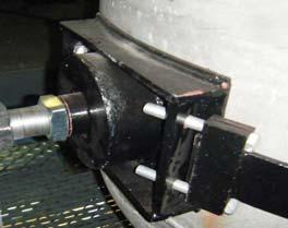
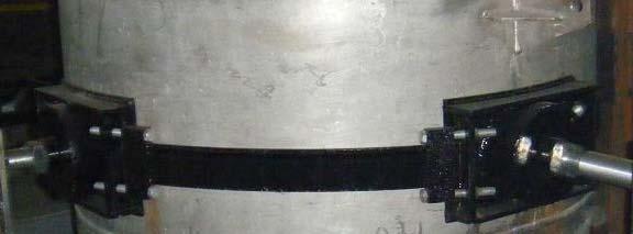
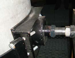
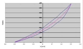

9 Fig. P1. Grip ways for SERB type pipe supports- anchoring solution Strength - distortion hysteresis characteristics of SERB supports, may be of the following shapes (Fig. P2): Fig. P2. Hysteresis characteristics of strength deformation for SERB type supports 3
 [KN] x 2) [mm] Fy 1) [KN] y 2) [mm] L 3) [mm] D 3) [mm] a 3) [mm] m 5) [kg] SERB-P1-10-3-3 <10 ±10 <3 ±5 120")
 normal values of axial and normal load (can be reached also for higher values); 2) - the maximum value of elastic for x and displacement produced by quasi-steady force for y; out")

 direction to the axial force, the support can take dynamic loads, generally, with values below 0.")
10 PIPES - TECHNICAL DATA SHEET No. P1 1. Name: Elastic support with damping for pipes SERB-P1-Fx-Fy-n type SERB-P1-Fx-Fy-n Fx 1) [KN] x 2) [mm] Fy 1) [KN] y 2) [mm] L 3) [mm] D 3) [mm] a 3) [mm] m 5) [kg] SERB-P <10 ±10 <3 ± SERB-P ± ± SERB-P ± ± SERB-P ± ± ) normal values of axial and normal load (can be reached also for higher values); 2) - the maximum value of elastic for x and displacement produced by quasi-steady force for y; out of range the support behaves rigidly for larger loads and returns to elastic behavior within the interval; 3) - dimensions are between the given limits of usually supports; 4) mass is as a rough guide, is very dependent on the clamping elements; n - the maximum number of sandwich structures working in series or in parallel. 3. Loads and operation: the support can elastically over take over permanent and /or dynamic forces with damping, on axial direction (x). On the normal (y) direction to the axial force, the support can take dynamic loads, generally, with values below 0.3 from axial loading, in any direction, which it damps, (the reaction force is constant, with slight increase in the maximum deflection). Axial movements are elastic non-linear. The axial force deformation characteristic is of hysteretic type with no shock limitation of movements. 4. Damping: expressed as a ratio between energy dissipation per cycle of oscillation / elastic energy developed in oscillation cycle. Values are between 15% and 60%, on axial direction, depending on pretension of supports. On a normal direction to the axial direction practically there is a constant damping force with a value ranging between 0.1 and 0.3 of the axial loading. 5. Fastening: fastening to the pipeline or the host structure is made through a mobile shaft which is fixed to the pipe with a pre-tightened clamp and to the support structure fastening is made either with a dummy pin / rigid shaft, or through a plate welded on the support body. 6. Performance: The support is not affected by: variations in temperature and humidity, radiation field, aging, potential blocking. No maintenance required during life span. 4
 [KN] x 2) [mm] Fy 1) [KN] y 2) [mm] L 3) [mm] D 3) [mm] s 3) [mm] m 4) [kg] SERB-P2-10-3-3 <10 ±5 <3 ±5 200 300")
 - normal values of axial load and normal (can be reached also for higher values); 2) - the maximum value of elastic deformation for x and displacement produced by quasi-steady")

11 PIPES- TECHNICAL DATA SHEET No. P2 1. Name: Elastic support with damping for pipes SERB-P2-Fx-Fy-n type SERB-P2-Fx-Fy-n Fx 1) [KN] x 2) [mm] Fy 1) [KN] y 2) [mm] L 3) [mm] D 3) [mm] s 3) [mm] m 4) [kg] SERB-P <10 ±5 <3 ± SERB-P ± ± SERB-P ± ± SERB-P ± ± ) - normal values of axial load and normal (can be reached also for higher values); 2) - the maximum value of elastic deformation for x and displacement produced by quasi-steady force for y; out of range the support behaves rigidly for larger loads and returns to elastic behavior within the interval; 3) - dimensions are between the given limits of normal supports; 4) mass is as a rough guide, is very dependent on the clamping elements; n - the maximum number of sandwich structures working in series or in parallel. 3. Loads and operation: the support can elastically take over permanent and /or dynamic forces (Fx) with damping, on axial direction (x). On the normal direction to the axial force Fx (y), the support can takeover dynamic loads, generally, with values below 0.3 of axial load, in any direction, which it damps, (the reaction force is constant, with slight increase in the maximum displacement). Axial movements are elastic non-linear, and the normal ones can be imposed within the desired limits for axial movements. The axial force deformation characteristic is of hysteretic type with no shock limitation of movements. 4. Damping: expressed as a ratio between energy dissipation per cycle of oscillation / elastic energy occurred in oscillation cycle. Values are between 15% and 60%, on axial direction, depending on stressing of supports. 5. Fastening: fastening to the pipeline is made by pre-tightening a number of 1, 2, 3 or 4 supports by some belts, and to the host structure fastening is usually made by some bolt nuts on a plate attached to the host structure. The supports can be pre-stressed between pipe and anchoring plate. 6. Performance: The support is not affected by: variations in temperature and humidity, radiation field, aging, potential blocking. No maintenance required during life span. 5
 [KN] x 2) [mm] Fy 1) [KN] y 2) [mm] L 3) [mm] B 3) [mm] H 3) [mm] m 4) [kg] SERB-P3-50-15-2 <50 ±5 5 15 ±100")
 - normal values of axial and normal loads (can be reached also for higher values); 2) - the maximum value of elastic deformation for x and displacement")
 mass is as a rough guide, is very dependent on the clamping elements; n - the maximum number of sandwich structures working in series or in parallel. 3.")
12 PIPES - TECHNICAL DATA SHEET No. P3 1. Name: Elastic support with damping for pipes SERB-P3-Fx-Fy-n type SERB-P3-Fx-Fy-n Fx 1) [KN] x 2) [mm] Fy 1) [KN] y 2) [mm] L 3) [mm] B 3) [mm] H 3) [mm] m 4) [kg] SERB-P <50 ± ± SERB-P ± ± SERB-P ± ± SERB-P ± ± ) - normal values of axial and normal loads (can be reached also for higher values); 2) - the maximum value of elastic deformation for x and displacement produced by quasi-steady force for y; out of range the support behaves rigidly for larger loads and returns to elastic behavior within the interval; 3) - dimensions are between the given limits of normal supports; 4) mass is as a rough guide, is very dependent on the clamping elements; n - the maximum number of sandwich structures working in series or in parallel. 3. Loads and operation: the support can elastically take over permanent and /or dynamic forces with damping, on axial direction (x). On the normal direction to the axial force Fx (y), the support can take over dynamic loads generally, with values between 0.1 and 0.3 (or higher). Of the axial load, in any direction, which it damps, (the reaction force is constant, with slight increase in the maximum movement). Axial movements are elastic non-linear, and the normal ones to axial movements can be imposed within the desired limits. The axial force deformation characteristic is of hysteretic type with the no shock limitation of movements. 4. Damping: expressed as a ratio between energy dissipation per cycle of oscillation / elastic energy developed in oscillation cycle. Values are between 20% and 80%, depending on the prestressing of supports. 5. Fastening: fastening to the pipeline is usually made with 2 straps and to the support structure by any desired means welding, bolts, and joints. 6. Performance: The support is not affected by: variations in temperature and humidity, radiation field, aging, potential blocking. No maintenance required during life span. 6
 [KN] x 2) [mm] Fy 1) [KN] y 2) [mm] L 3) [mm] D 3) [mm] a 3) [mm] m 4) [kg] SERB-P4-100-30-4 <100 ±15 <30 ±1")
 - normal values of axial and normal loads (can be reached also for higher values); 2) - the maximum amount of elastic deformation for x and displacement produced")
13 PIPES - TECHNICAL DATA SHEET No. P4 1. Name: Elastic support with damping for pipes SERB-P4-Fx-Fy-n type SERB-P4-Fx-Fy-n Fx 1) [KN] x 2) [mm] Fy 1) [KN] y 2) [mm] L 3) [mm] D 3) [mm] a 3) [mm] m 4) [kg] SERB-P <100 ±15 <30 ± SERB-P ± ± SERB-P ± ± SERB-P ± ± ) - normal values of axial and normal loads (can be reached also for higher values); 2) - the maximum amount of elastic deformation for x and displacement produced by quasi-steady force for y; out of range the support behaves rigidly for larger loads and returns to elastic behavior within the interval; 3) - dimensions are between the given limits of normal supports; 4) mass is as a rough guide, is very dependent on the clamping elements; n - the maximum number of sandwich structures working in series or in parallel. 3. Loads and operation: the support can elastically takeover permanent and/or dynamic forces with damping, on axial direction (x). Normal loads at the axial force do not block the functioning of the support for values under 0,4 of the axial force. Axial movements are nonlinear elastic, and the normal ones to the axis of the support are very low. The axial force deflection/deformation characteristic is of hysteretic type with the no shock limitation of movements. 4. Damping: expressed as a ratio between energy dissipation per cycle of oscillation / elastic energy developed in an oscillation cycle. Values are between 20% and 80%, depending on the pre-stressing of supports. 5. Fastening: fastening to the pipeline or to the support structure is made by any desired means welding, bolts, and joints. 6. Performance: The support is not affected by: variations in temperature and humidity, radiation field, aging, potential blocking. No maintenance required during life span. 7
 [KN] x 2) [mm] Fy 1) [KN] y 2) [mm] H 3) [mm] D 3) [mm] m 4) [kg] SERB-P5-100-30-3 <100 <±15 <30 <±5 120 200")
 - normal values of axial and normal loads (can be reached also for higher values); 2) - the maximum amount of elastic deformation for x and displacement produced by quasi-steady")

14 PIPES - TECHNICAL DATA SHEET No. P5 1. Name: Elastic support with damping for pipes SERB-P5-Fx-Fy-n type SERB-P5-Fx-Fy-n Fx 1) [KN] x 2) [mm] Fy 1) [KN] y 2) [mm] H 3) [mm] D 3) [mm] m 4) [kg] SERB-P <100 <±15 <30 <± SERB-P <±20 <150 <± SERB-P <±20 <500 <± SERB-P <±20 <1000 <± ) - normal values of axial and normal loads (can be reached also for higher values); 2) - the maximum amount of elastic deformation for x and displacement produced by quasi-steady force for y; out of range the support behaves rigidly for larger loads and returns to elastic behavior within the interval; 3) - dimensions are between the given limits of normal supports; 4) mass is as a rough guide, is very dependent on the clamping elements; n - the maximum number of sandwich structures working in series or in parallel. 3. Loads and operation: the support can elastically takeover permanent and /or dynamic forces with damping, on axial direction (x). Normal loads at the axial force do not block the functioning of the support for values under 0.4 of the axial force, on any direction, which it damps, (the reaction force is constant, with a slight increase at maximum displacements). Axial displacements are non-linear elastic, and the normal ones can be imposed within the desired limits for axial movements. The axial force deformation characteristic is of hysteretic type with the no shock limitation of displacements. 4. Damping: expressed as a ratio between energy dissipation per cycle of oscillation / elastic energy occurred in an oscillation cycle. Values are between 20% and 80%, depending on prestressing of supports. 5. Fastening: fastening to the pipeline is usually made with 1 or 2 straps collars, fixed on the mobile head of the support and attachment to the support structure is made by any desired means welding, bolts, joints. 6. Performance: The support is not affected by: variations in temperature and humidity, radiation field, aging, potential blocking. No maintenance required during life span. 8
 [KN] x 2) [mm] Fy 1) [KN] y 2) [mm] L 3) [mm] H 3) [mm] a 3) [mm] m 4) [kg] SERB-P6-500-200 <500 ±20 <200 0 500")
 - normal values of axial and normal loads (can be reached also for higher values); 2) - the maximum amount of elastic deformation for x and/or;")
15 PIPES - TECHNICAL DATA SHEET No. P6 1. Name: Elastic support with damping for pipes SERB-P6-Fx-Fy-n type SERB-P6-Fx-Fy Fx 1) [KN] x 2) [mm] Fy 1) [KN] y 2) [mm] L 3) [mm] H 3) [mm] a 3) [mm] m 4) [kg] SERB-P <500 ±20 < SERB-P ±30 < SERB-P ±50 < SERB-P ±60 < ) - normal values of axial and normal loads (can be reached also for higher values); 2) - the maximum amount of elastic deformation for x and/or; displacement produced by quasi-steady force for y; out of range the support behaves rigidly for larger loads and returns to elastic behavior within the interval; 3) - dimensions are between the given limits of normal supports; 4) mass is as a rough guide, is very dependent on the clamping elements. 3. Loads and operation: the support can elastically take over permanent and/or dynamic forces Fx with damping, on axial direction (x). Normal loads at the axial force (y) do not block the functioning of the support for values under 0,4 of the axial force. Axial movements are nonlinear elastic and the normal displacements to the axial movements may be imposed in the desired limits. The axial force deformation characteristic is of hysteretic type with no shock limitation of movements. It is recommended to be used in overtaking the thermal expansions and damping the dynamic loads. 4. Damping: expressed as a ratio between energy dissipation per cycle of oscillation / elastic energy developed in an oscillation cycle. Values are between 40% and 95%, depending on prestressing supports. The force deformation diagram hysteresis can be done in any shape for the level of reaction force (damping) and also for the level of movement which can be of any level with integral or partial consumption of mechanic work on return. 5. Fastening: fastening to the pipeline or to the support structure is done through the fix and mobile clamp or by any desired means welding, bolts, and joints. 6. Performance: The support is not affected by: variations in temperature and humidity, radiation field, aging, potential blocking. No maintenance required during life span. 9
16 RAAN SITON (III) MECHANICAL ISOLATORS FOR EQUIPMENT Contact persons: ADRIAN PANAIT - GENERAL DIRECTOR P.O.B.5204-MG-4, TEL/FAX +40-(0) , panaita@router.citon.ro PROJECT MANAGER Ph.D. VIOREL SERBAN serbanv@router.citon.ro Tel Tel Fax: 40-(0)
17 EQUIPMENT GENERAL OVERVIEW SERB-Ei-Fz-axy- xy type equipment isolators Equipment such as electrical and automation cabinets, process computers, motor-pump assemblies, rotating equipment, electrical transformers, control panels are subject to dynamic actions such as shocks, vibrations and seismic movements throughout their lifetime. Dynamic actions (excitement) may be generated by the equipment and in such cases the environment may be affected or such dynamic actions may come from the environment and affect the operation of the equipment. Removal of the negative effects of dynamic actions on equipment and environment is achieved by isolating them from the foundation. In this case, a special attention should be given to the technological connections of the equipment (cables, pipes, and tubing) with the rest of the system. These connections should be so made that isolated equipment should not transfer (or over take) shocks, vibrations or seismic movements from the environment. Also, the coaxial settings and flatness of the equipment or its components is need to be provided within the limits prescribed by the supplier and isolating conditions. At the same time, the proposed isolating system must take over the permanent weight of the equipment over which three-dimensional dynamic loads overlap, loads which have to be taken over with minimum movement and which are diminished in a reduced number of oscillation cycles. Depending on the share of dynamic actions generated by the equipment functioning towards the dynamic actions generated by earthquakes, the isolation solutions differ. At the same time, one must consider the self - weight of the equipment, maximum movement on freedom degrees and anchoring solution. For the equipment where during operation vibrations or shocks are prevailing, SERB-E2-Fzaxy- xy, SERB-E3-Fz-axy- xy, SERB-E4-Fz-axy- xy type isolators are recommended. These isolators partially cut-off the transfer of a seismic action (or any other external excitation) from the foundation to the equipment and they absorb their movement, reducing the energy built-up in the oscillating system (equipment isolators),and also reducing the stress in the equipment and foundation anchoring. For the equipment where during operation seismic actions are prevailing (or any external excitation with dominant movement in horizontal plane), SERB-E1-Fz-axy- xy, SERB-E5-Fz-axy- xy, SERB-E6-Fz-axy- xy type isolators are recommended. These insulators practically cut to zero the seismic action in any direction on a horizontal plane. On a vertical direction, these insulators are rigid and take over almost entirely the dynamic vertical action. In case a total isolation on a vertical and horizontal direction is desired, the two isolator types can be combined to result in a higher isolator. In this case the total isolation of the equipment is ensured but problems may occur within technological connections with the rest of the system, which are now more severe and they must be properly solved. Furthermore, bending problems may occur to the equipment during earthquakes and might disrupt their operation. Compared to conventional solutions used until now, the proposed solution has the advantage that the rigidity of isolators is geometrically nonlinear type and is not affected by overloading. Furthermore, isolators can be made for any desired stiffness and any damping capacity without having overstressed components inside. 1
 [KN] axy 2) [g] xy 3) [mm] L 4) [mm] l 4) [mm] H 4) [mm] m 5) [kg] SERB-E1-1000-0,008-150 <1000 <0,008 <±150 1000 1500 800 1000 60")
 normal values of vertical load (can be obtained also for higher values); 2) maximum value of the acceleration transmitted to the isolated cabinet on x")
 the mass is indicative. 3. Loads and operation: the isolator can take over permanent vertical loads which it isolates for dynamic horizontal actions.")

18 EQUIPMENT - TEHNICAL DATA SHEET No. E1 1. Name: Cabinet isolators SERB-E1-Fz-axy- xy SERB-E1-Fz-axy- xy Fz 1) [KN] axy 2) [g] xy 3) [mm] L 4) [mm] l 4) [mm] H 4) [mm] m 5) [kg] SERB-E , <1000 <0,008 <± SERB-E , <2000 <0,008 <± SERB-E , <1000 <0,01 <± SERB-E , <2000 <0,01 <± ) normal values of vertical load (can be obtained also for higher values); 2) maximum value of the acceleration transmitted to the isolated cabinet on x and y directions; 3) maximum value of relative movements on x and y directions admitted by the isolator with elastic limitations; 4) the dimensions are between the limits given for the normal isolators; 5) the mass is indicative. 3. Loads and operation: the isolator can take over permanent vertical loads which it isolates for dynamic horizontal actions. On demand, vertical isolation can also be performed. In this case the height of the isolator increases three times and its mass five times. On a horizontal direction, the isolator cuts off the transfer of dynamic action at values under axy for any seismic action, if the relative horizontal movements are under xy. Higher relative movements can also be ensured for larger sized isolator in plan. 4. Fastening : fastening of the isolator to the cabinet is made by bolting to the cabinet pedestal and by welding or bolts to the host structure. 5. Performance: the isolator is not affected by: temperature and moisture variations, radiations field, aging, potential blocking. No maintenance required during its life span. 2
 [KN] z 2) [mm] xy 3) [mm] D 4) [mm] H 4) [mm] m 5) [kg] SERB-E2-50-7-2 <50 <±7 <±2 100 140 15 40 1 5")
; 2) maximum value of elastic movement on vertical; 3) maximum value of movement in horizontal plane; 4) dimensions are between the limits given for the normal")

19 EQUIPMENT - TEHNICAL DATA SHEET No. E2 1. Name: Low and medium equipment isolators SERB-E2-Fz- z- xy SERB-E2-Fz- z- xy Fz 1) [KN] z 2) [mm] xy 3) [mm] D 4) [mm] H 4) [mm] m 5) [kg] SERB-E <50 <±7 <± SERB-E <100 <±10 <± SERB-E <300 <±10 <± SERB-E <600 <±10 <± ) normal values of vertical load (can be obtained also for higher values); 2) maximum value of elastic movement on vertical; 3) maximum value of movement in horizontal plane; 4) dimensions are between the limits given for the normal isolators; 5) the mass is indicative. 3. Loads and operation: the isolators can take over permanent vertical loads which it isolates for dynamic horizontal and vertical actions. Tuning for the horizontal position the equipment is made by pre-tightening the package lower isolators equipment leg plate upper isolators. On a horizontal direction, the isolators damp loads. Relative higher movements can be ensured if the stability requirements allow it. If the equipment registers high movement during operation from thermal expansion, on a certain direction, the isolators can be rectangular, with different movement on x and y directions. The vertical movement must be correlated with the requirement to avoid the resonance area of the excitation equipment (dynamic action). 4. Fastening: fastening of the equipment with this type of isolators, is made by installing an isolator on each grip anchor of the equipment, under the plate leg of the equipment and one on the leg plate of the equipment; The assembly is pre-tightened with bolts. 5. Performance: the isolator is not affected by: temperature and moisture variations, radiations field, aging, potential blocking. No maintenance required during its life span. 3
 [KN] z 2) [mm] xy 3) [mm] D 4) [mm] L 4) [mm] H 4) [mm] m 5) [kg] SERB-E3-100-10-3 <100 <±10 <±3 200 300 300 400")
 normal values of vertical load (can be obtained also for higher values); 2) maximum value of elastic movement on vertical; 3) maximum value of movement in horizontal plane; 4) dimensions")

. 4.")
20 EQUIPMENT - TEHNICAL DATA SHEET No. E3 1. Name: Medium and heavy equipment isolators SERB-E3-Fz- z- xy SERB-E3-Fz- z- xy Fz 1) [KN] z 2) [mm] xy 3) [mm] D 4) [mm] L 4) [mm] H 4) [mm] m 5) [kg] SERB-E <100 <±10 <± SERB-E <500 <±10 <± SERB-E <1000 <±10 <± SERB-E <2000 <±10 <± ) normal values of vertical load (can be obtained also for higher values); 2) maximum value of elastic movement on vertical; 3) maximum value of movement in horizontal plane; 4) dimensions are between the limits given for the normal isolators; 5) the mass is indicative. 3. Loads and operation: the isolators can take over permanent vertical loads which it isolates for dynamic horizontal and vertical actions. On a horizontal direction, the isolators over take and damp loads. Relative higher movements can be ensured if the stability requirements allow it. The vertical movement must be correlated with the requirement to avoid the resonance area of the excitation equipment (dynamic action). 4. Fastening: fastening of the equipment with this type of isolators is made by simply placing the equipment on isolators and blocking the lateral movements by stoppers. Fastening holes can be pre-drilled in the support plate through which the isolators are bolted on the equipment plate leg. Insulators are recommended for the equipment subject to shocks and vibrations. 5. Performance: the isolator is not affected by: temperature and moisture variations, radiations field, aging, potential blocking. No maintenance required during its life span. 4
 [KN] z 2) [mm] xy 3) [mm] D 4) [mm] L 4) [mm] H 4) [mm] m 5) [kg] SERB-E4-500-10-3 <500 <±10 <±3 180 260 400 600 200 300 140")
 normal values of vertical load (can be manufacture also for higher values); 2) maximum value of elastic movement on vertical; 3) maximum value of movement in horizontal plane; 4)")

. 4.")
21 EQUIPMENT - TEHNICAL DATA SHEET No. E4 1. Name: Heavy equipment isolators SERB-E3-Fz- z- xy SERB-E4-Fz- z- xy Fz 1) [KN] z 2) [mm] xy 3) [mm] D 4) [mm] L 4) [mm] H 4) [mm] m 5) [kg] SERB-E <500 <±10 <± SERB-E <1000 <±10 <± SERB-E <2000 <±10 <± SERB-E <4000 <±10 <± ) normal values of vertical load (can be manufacture also for higher values); 2) maximum value of elastic movement on vertical; 3) maximum value of movement in horizontal plane; 4) dimensions are between the limits given for the normal isolators; 5) the mass is indicative. 3. Loads and operation: the isolator can take over permanent vertical loads which it isolates for dynamic horizontal and vertical actions. On a horizontal direction, the isolator damps loads. Relative higher movements can be ensured if the stability requirements allow it. The vertical movement must be correlated with the requirement to avoid the resonance area of the excitation equipment (dynamic action). 4. Fastening: fastening of the equipment with this type of insulator is made by simply placing the equipment on insulators and blocking the lateral displacements by stoppers. Fastening holes can be pre-drilled in the support plate through which the isolators are fixed on the equipment plate leg. Isolators are recommended for the equipment subject to shocks and vibrations. 5. Performance: the isolator is not affected by: temperature and moisture variations, radiations field, aging, potential blocking. No maintenance required during its life span. 5
22 EQUIPMENT - TEHNICAL DATA SHEET No. E5 1. Name: Friction isolators for medium and heavy equipment SERB-E5-Fz-axy- xy SERB-E5-Fz-axy- xy Fz 1) [KN] axy 2) [g] xy 3) [mm] L 4) [mm] H 4) [mm] m 5) [kg] SERB-E , <3000 <0,007 <± <410 <2000 SERB-E , <5000 <0,007 <± <500 <3500 SERB-E , <7000 <0,007 <± <600 <6700 1) normal values of vertical load (can be obtained also for higher values); 2) maximum value of the acceleration transmitted to the isolators equipment on x and y directions; 3) maximum value of relative movements on x and y directions admitted by the isolator with non-linear elastic limitations; 4) the dimensions are between the limits given for the normal isolators; 5) the mass is indicative. 3. Loads and operation: the isolator can take over permanent vertical loads which it isolates for dynamic horizontal actions (earthquakes). On demand, vertical isolation can also be performed. In this case the height of the isolator increases two times and its mass two times. On a horizontal direction, the isolator cuts off the transfer of the dynamic action at values under axy for any seismic action, if the relative horizontal movements are under xy. 4. Damping: expressed as a ratio between energy dissipation per cycle of oscillation / elastic energy occurred in the oscillation cycle. Values are between 3% and 15% for movements in the horizontal plane. They can be also made with a higher damping capacity but this is not recommended because the isolation degree is reduced and higher accelerations are transferred to the isolated equipment with a proper reduction of relative movements on a horizontal plane. These are recommended for equipment which are not subject to shocks or vibrations during operation and have no rigid connections with the rest of the system in which they are integrated, but are installed on seismic sites. In case the seismic loads and shock and vibrations are important, the vertical isolation is also recommended. 5. Fasteninig: fastening of the isolator to the equipment and foundation is made by bolting. 6. Performance: the isolator is not affected by: temperature and moisture variations, radiations field, aging (safety and stability elements) and blocking hazard. No substitution is necessary throughout the lifespan of the equipment. The elements that determine the rigidity on a horizontal plane 6
23 (vibration period of the equipment and the return to its initial position) can be modified (after the installation) without affecting the operation of the isolator or the stability of the equipment. EQUIPMENT - TEHNICAL DATA SHEET No. E6 1. Name: Medium and heavy equipment isolators with friction and sliding SERB-E6-Fz-axy- xy SERB-E6-Fz-axy- xy Fz 1) [KN] axy 2) [g] xy 3) [mm] L 4) [mm] H 4) [mm] m 5) [kg] SERB-E , <6000 <0,013 <± <325 <1400 SERB-E , <9000 <0,013 <± <500 <3000 SERB-E , <12000 <0,013 <± <600 <6000 1) normal values of vertical load (can be obtained also for higher values); 2) maximum value of the acceleration transmitted to the isolated equipment on x and y directions; 3) maximum value of relative movements on x and y directions admitted by the isolator with non-linear elastic limitations; 4) the dimensions are between the limits given for the normal isolators; 5) the mass is indicative. 3. Loads and operation: the insulator can take over permanent vertical loads which it isolates for dynamic horizontal actions (earthquakes). On demand, vertical isolation can also be performed. In this case the height of the isolator increases two times and its mass two times. On a horizontal direction, the isolator cuts off the transfer of dynamic action at values under axy for any seismic action, if the relative horizontal movements are under xy. 4. Damping: expressed as a ratio between energy dissipation per cycle of oscillation / elastic energy occurred in the oscillation cycle. Values are between 7% and 20% for the movements on horizontal plane. They can be also made with a higher damping capacity but it is not recommended because the isolation degree is reduced and higher accelerations are transferred to the isolated equipment, with a proper reduction of relative movements on a horizontal plane. These are recommended for equipment which are not subject to shocks or vibrations during operation and have no rigid connections with the rest of the system in which they are integrated, but are installed on seismic sites. In case the seismic loads and shock and vibrations are important, the vertical isolation is also recommended. 5. Fastening: fastening of the isolator to the equipment and foundation is made by bolting. 6. Performance: the insulator is not affected by: temperature and moisture variations, radiations field, aging (safety and stability elements) and blocking hazard. No change is necessary throughout the lifespan of the equipment. The elements that determine the rigidity on a 7
24 horizontal plane (vibrating time of the equipment and the return to its initial position) can be modified (after the installation) without affecting the operation of the isolator or the stability of the equipment. 8
25 RAAN SITON (IV) MECHANICAL DEVICES AND ISOLATORS FOR BUILDINGS Contact persons: ADRIAN PANAIT - GENERAL DIRECTOR P.O.B.5204-MG-4, TEL/FAX +40-(0) , panaita@router.citon.ro PROJECT MANAGER Ph.D. VIOREL SERBAN serbanv@router.citon.ro Tel Tel Fax: 40-(0)
26 BUILDINGS GENERAL OVERVIEW SERB-Bi-Fx-Fyz telescopic device for passive energy scattering and SERB-Bi-Fz-axy- xy building isolators with rolingane friction Buildings are generally big sized structures, subjected to high static and dynamic loads during their life. Among the dynamic loads (wind, explosions, earthquakes), earthquakes can have a devastating damaging effect. This is possible both due to the direct dynamic action on the building (the seismic acceleration) which has high values and to the fact that the building foundation ground assembly make-up an oscillating system which, in many cases, accumulates kinetic and potential energy from the ground repeated seismic movement, which leads to the seismic response amplification in accelerations (in horizontal plane) a few times higher than the direct seismic action. The innovative methods for protecting the buildings from the seismic actions are connected either to the dissipation of a higher seismic energy transferred to the building by fitting mechanical devices to the building structure, in order to allow also the control of floor relative movements, or to a cut off in the seismic action transfer from the ground to the building in any direction in horizontal plane by isolating them (not recommended on vertical direction, for common building isolation as the self-weight loads produce differential distortions of the vertical isolators with the resistance elements overstress because of the differential distortion of the supports). SERB devices developed by SITON can be used for the following solutions to reduce dynamic (seismic) loads on buildings: 1. The passive dissipation of kinetic and potential energy of a building and the control of their relative movement (and between the segments of the adjoining buildings). In this case, in the resistance elements of the building (pillars, beams) there are no local damages known as plastic hinges. The dissipation of the energy built-up in the building is ensured by the telescopic devices fitted in certain bracing panels, preferably symmetrical, in the lower part of the building. (Fig. B1). Fig. B1. SERB telescopic devices installation in the centrical and excentrical braces and around nodes. In order to avoid the collision between the segments of the adjoining buildings, it is recommended to fit in such horizontal devices between the segments. 1


27 The connection between the devices and the structure can be made by welding or bolting, and does not require hinge joints, as the devices are not affected by coaxial misalignments of the fastening points and by the overtaking of some normal forces at the device axis or moments. The devices can actually be manufactured for any value of the dynamic loads and for any distortion, but it is recommended that their distortion should limit the floor relative movement to values that do not generate local damage of the building structure. The devices can also be used to strengthen the existent buildings, in which case the absorption of the axial loads from the bracing using the telescopic devices is ensured through the metallic lining of the nodes, columns and beams of the braced panel, provided that the structure is a reinforced concrete structure. If there is a metallic structure, the connection of the devices to the braced panel is usually made through metallic gussets welded to the beams and columns. 2. Seismic isolation of buildings Cutting off the transfer of the seismic action from the foundation ground to the building may be made at any level, dividing the building in two parts: - Infrastructure embedded in the ground - Isolated superstructure The infrastructure embedded in the ground may include: a slab type foundation, the foundation and basement or foundation, the basement and the ground floor, depending on the type of building and its functions. SERB type isolators have a low height and they are fastened on the infrastructure and suprastructure by threaded bolts in the parts embedded in their structure (Fig. B2). Fig. B2. Example of isolation devices installation between infrastructure and superstructure SERB type isolators do not require maintenance over the whole lifespan of the objective and show a major advantage as their rigidity on horizontal direction can be adjusted or completely modified after fitting the supports in the building without affecting the building stability and safety, anytime during the lifespan of the building. The damping capacity of the isolator can be realized in a relatively wide range. A good isolation involves a small damping capacity because the seismic action is transferred to the superstructure also by the damping force. A relatively large damping reduces the relative movement between infrastructure and superstructure. If an important limitation of this 2
 [KN] x 2) [mm] Fyz 1) [KN] yz 2) [mm] L 3) [mm] D 3) [mm] a 3) [mm] m 4) [kg] SERB-B1-600-120-4")
; 2) maximum value of elastic deforming with damping on x and y directions, outside the range the device is behaving rigidly for larger")

28 displacement is desired, the SERB-B2-Fx-Fyz telescopic devices can be mounted between the infrastructure and the superstructure in parallel with the isolators. BUILDINGS - TECHNICAL DATA SHEET No. B1 1. Name: Telescopic device for passive energy dissipation - SERB-B1-Fx-Fyz-n SERB-B1-Fx-Fyz-n Fx 1) [KN] x 2) [mm] Fyz 1) [KN] yz 2) [mm] L 3) [mm] D 3) [mm] a 3) [mm] m 4) [kg] SERB-B <600 <±20 <120 <± SERB-B <1000 <±20 <200 <± SERB-B <2000 <±25 <400 <± ) normal load values (can be manufactured also for higher values); 2) maximum value of elastic deforming with damping on x and y directions, outside the range the device is behaving rigidly for larger loads and returns to elastic behavior inside the range; 3) - the dimensions are comprised within the given limits for normal devices; 4) the mass is indicative; n maximum number of sandwich structures. 3. Loads and operation: The device controls the relative interstory level distortion of building by the installation in centrically, eccentrically braces or around nodes in panels symmetrically distributed in a building. The device can elastically overtake with damping, the axial forces (x). Normal loads (y) do not block the functioning of the device for values below 0.2 of the axial force. The axial force distortion characteristic is of hysteresis type, with no shock limitation of deflections. 4. Damping: Expressed as a ratio between energy dissipation per cycle of oscillation / elastic energy developed in the oscillation cycle. Values between 20% and 80%, depending on pre-stressing the devices. 5. Fastening: The device fastening on braces can be done as per any desired form welding, bolting, and jointing. 6. Performance: The device is not affected by: temperature and moisture variations, radiations field, aging, potential blocking. No maintenance required during life span. 3
 [KN] x 2) [mm] Fyz 1) [KN] yz 2) [mm] L 3) [mm] H 3) [mm] a 3) [mm] m 4) [kg] SERB-B2-1000-200 <1000 <±30")
; 2) maximum value of elastic deforming with damping on x and y (on y there are no movement recommended) directions, outside the range the")

29 BUILDINGS - TECHNICAL DATA SHEET No. B2 1. Name: Telescopic device for passive energy dissipation - SERB-B2-Fx-Fyz SERB-B2-Fx-Fyz Fx 1) [KN] x 2) [mm] Fyz 1) [KN] yz 2) [mm] L 3) [mm] H 3) [mm] a 3) [mm] m 4) [kg] SERB-B <1000 <±30 <200 <± SERB-B <4000 <±40 <800 <± SERB-B <6000 <±60 <1200 <± ) normal load values (can be manufactured also for higher values); 2) maximum value of elastic deforming with damping on x and y (on y there are no movement recommended) directions, outside the range the device is behaving rigidly for larger loads and returns to elastic behavior inside the range; 3) - the dimensions are comprised within the given limits for normal devices; 4) the mass is indicative. 3. Loads and operation: The device controls the relative interstory displacements of buildings by their installation in centrical, excentrical braces or around nodes in panels symmetrically distributed in a building. The device can elastically overtake with damping the axial forces x. Normal loads (y) do not block the functioning of the device for values below 0.2 of the axial force. The axial force distortion characteristic is of hysteresis type, with no shock limitation of deflections. 4. Damping: Expressed as a ratio between energy dissipation per cycle of oscillation / elastic energy developed in the oscillation cycle. Values between 60% and 100%, depending on prestressing the devices. 5. Fastening: The device fastening on the braces can be done in any desired form welding, bolting and jointing. 6. Performance: The device is not affected by: temperature and moisture variations, radiations field, aging, potential blocking. No maintenance required during life span. 4
 [KN] axy 2) [g] xy 3) [mm] L 4) [mm] H 4) [mm] m 5) [kg] SERB-B3-3000-0,007-300 <3000 <0,007 <±300 1000")
30 BUILDINGS- TECHNICAL DATA SHEET No. B3 1. Name: Building isolators with rolling friction - SERB-B3-Fz-axy- xy SERB-B3-Fz-axy- xy Fz 1) [KN] axy 2) [g] xy 3) [mm] L 4) [mm] H 4) [mm] m 5) [kg] SERB-B , <3000 <0,007 <± <410 <2000 SERB-B , <5000 <0,007 <± <500 <3500 SERB-B , <7000 <0,007 <± <600 <6500 1) - normal vertical load values (can be obtained also for higher values); 2) maximum value of the acceleration transmitted to the isolated building on x and y directions; 3) maximum values of the relative movement on x and y directions admitted by the isolator with non-linear elastic limitations; 4) the dimensions are comprised within the given limits for normal isolators; 5) - the mass is indicative. 3. Loads and operation: The isolator can takeover permanent vertical loads that it isolates for dynamic horizontal actions. On demand, the isolation can be performed also on a vertical direction. In this case, the height of the isolator is increased by approx 2 times and its mass 2 times. On a horizontal direction, the isolator cuts off the transfer of the dynamic action to values under axy for any seismic action if relative horizontal movements are under xy. 4. Damping: Expressed as a ratio between energy dissipation per cycle of oscillation / elastic energy developed in the oscillation cycle. Values are between 3% and 15% on the horizontal movement. They can be also made with a higher damping capacity but it is not recommended because the isolation degree is reduced and higher accelerations are transferred to the isolated superstructure with a proper reduction of relative movements in a horizontal plane. In case an increase of damping is needed, the isolators can be installed parallel to the SERB-B2-Fx-Fyz devices connected between the isolated superstructure and foundation. 5. Fastening: The isolator fastening on the superstructure and embedded infrastructure is made by bolting. 6. Performance: The isolators are not affected by: temperature and moisture variations, radiation field, aging (safety and stability elements), potential blocking. No maintenance required during life span. The elements that determine the rigidity on a horizontal plane (vibration time of superstructure and its return to its initial position) can be modified (after the installation) without affecting the operation of the isolator or the stability of the building. 5
 [KN] axy 2) [g] xy 3) [mm] L 4) [mm] H 4) [mm] m 5) [kg] SERB-B4-6000-0,013-300 <6000 <0,013 <±300 1000 <325")
; 2) maximum value of the acceleration transmitted to the isolated building on x and y directions; 3) maximum values of the relative movement on x and y directions admitted by the isolators")
31 BUILDINGS- TECHNICAL DATA SHEET No. B4 1. Name: Building isolators with sliding friction SERB-B4-Fz-axy- xy SERB-B4-Fz-axy- xy Fz 1) [KN] axy 2) [g] xy 3) [mm] L 4) [mm] H 4) [mm] m 5) [kg] SERB-B , <6000 <0,013 <± <325 <1400 SERB-B , <9000 <0,013 <± <500 <3000 SERB-B , <12000 <0,013 <± <600 <6000 1) - normal vertical load values (can be obtained also for higher values); 2) maximum value of the acceleration transmitted to the isolated building on x and y directions; 3) maximum values of the relative movement on x and y directions admitted by the isolators with non-linear elastic limitations; 4) the dimensions are comprised within the given limits for normal isolators; 5) - the mass is indicative. 3. Loads and operation: The isolator can take over permanent vertical loads that it isolates for dynamic horizontal actions. On demand, the isolation can be also performed on a vertical direction. In this case, the height of the insulator is increased by approx 2 times and its mass 2 times. On a horizontal direction, the isolator cuts off the transfer of the dynamic actions for values under axy, for any seismic action, if relative horizontal movements are under xy. 4. Damping: Expressed as a ratio between energy dissipation per cycle of oscillation / elastic energy developed in the oscillation cycle. Values are between 7% and 20% for the horizontal movement plane. They can be also made with a higher damping capacity but it is not recommended because the isolation degree is reduced and higher accelerations are transferred to the isolated superstructure with a proper reduction of relative movements on a horizontal plane. In case an increase of damping is needed, the isolators can be installed parallel to the SERB-B2- Fx-Fyz devices connected between the isolated superstructure and the foundation. 5. Fastening: The isolator fastening on the superstructure and embedded infrastructure is made by bolting. 6. Performance: The device is not affected by: temperature and moisture variations, radiations field, aging (safety and stability elements) and potential blocking. No maintenance required during life span. The elements determining the rigidity on a horizontal plane (vibration time of superstructure and the return to its initial position) can be modified (after the installation) without affecting its operation of the isolator or the stability of the building. 6