. -, I AD-A * Final Report DTIC I DESIGN, FABRICATION, AND TESTING OF A COMPOSITE HULL FOR A TRACKED AMPHIBIOUS VEHICLE
|
|
|
- Evangeline Dorsey
- 5 years ago
- Views:
Transcription
1 AD-A FMC Report No DESGN, FABRCATON, AND TESTNG OF A COMPOSTE HULL FOR A TRACKED AMPHBOUS VEHCLE * Final Report DTC i VOLUME - TECHNCAL F FEB * H ssue Date: Aug 1, 1988 Period Covered: Jan 5, Feb 29, * Prepared Under Contract No. N C-0024 for m David Taylor Research Center FMC, Advanced Systems Center, 881 Martin Ave, Santa Clara, CA , *..!c1',,j;

2 E.~CArCflNO HS~u /.,--.,..zi,,/ REPORT DOCUMENTATON PAGE!a REPORT SECUPrY CLssCArON 'b RESTRCTVE MARKNGS UNCLASSFED Za SECURTY CLASSFCATON AUTHORTY 3 OSTRBUrONAVALABLTY OF REPORT 2b DECLASSFCATiONDOWNGRAONG SCHEDULE APPROVED FOR PUBLC RELEASE: DSTRBUTON UNLMTED 4 PERFORMNG ORGANZArON REPORT NUMBER(S) 5. MONTORNG ORGANZATON REPORT NUMBER(S) FMC-4686 DTRC - SSD - CR a NAME OF PERFORMNG ORGANZATON 6b OFFCE SYMBOL 7a. NAME OF MONTORNG ORGANZATON FMC Corporation (if applicable) DAVD TAYLOR RESEARCH CENTER Advanced Systems Center Ac. ADDRESS (City, State, and ZPCode) 7b ADDRESS (City, State, and ZP Code) 1105 Coleman Ave., P.O. Box 1201 Code 1240 San Jose, CA Bethesda, MD Sa. NAME OF FUNDNGSPONSORNG Bb. OFFCE SYMBOL 9. PROCUREMENT NSTRUMENT DENTFCATON NUMBER ORGANZATON (if applicable). DAVD TAYLOR RESEARCH CENTER N C-0024 Bc ADDRESS(City, State, and ZPCode) 10 SOURCE OF FUNDNG NUMBERS 1 1 TirLE (nclude Security Classification) PROGRAM PROJECT TASK WORK UNT ELEMENT NO NO NO. ACCESSON NO N CF43455 DN DESGN, FABRCATON, TESTNG OF COMPOSTE HULL FOR A TRACKED AMPHBOUS VEHCLE 12 PERSO 'AL AUTHOR(S) A. L. Foote 13a TYPE OF REPORT 13b. TME COVERED 14. DATE OF REPORT (Year, Month, Day) s. PAGE COUNT Final FROM 1/84 TO 2/ , January '6 SUPPLEMENTARY NOTATON 17 COSAT CODES 18. SUBJECT TERMS (Continue on reverse if necessary and identify by block number) FELD GROUP SUB-GROUP Composite Hulls, Composites, Armored-Tracked Vehicles 19 ABSTRACT (Continue on reverse if necessary and identify by block number) Lightweight composite hulls are needed for possible use on future amphibian vehicles. This contract provides for the design, fabrication, and testing of a composite hull vehicle. The activity reported herein includes documentation of the vehicle design; and design and fabrication of fifteen test panels of the proposed sidewall construction. This report also describes vehicle fabrication and compares weight and cost relative to a similar, aluminumhulled vehicle. The report recommends materials improvements, gives selection criteria, and documents materials testing. Also included is a finite element analysis providing structural evaluation on the effects of given vehicle loads and tile attachment stresses, along with a vehicle repairability study. The fabrication, inspection and testing activities are summarized along with the testing results at U. S. Marine Corps Amphibious Vehicle Test Branch, Camp Pendleton, California. 20 OiSPRi9UrjON/AVALABLTY OF ABSTRACT 21 ABSTRACT SECURTY CLASSFCATON "UNCLASSFED/UNLfMTEO 0 SAME A SRT 0Or USERS UNCLASSFED 22a 'JAME OF RESPONSBLE indvdual 22b TELEPHONE (nclude AreaCode) 22c. OFFCE SYMBOL Richard Swanek (301) FORM 1473, 84 MAR 83 APR edition may be used until exnausted,f( laty ('AssFi'ATON OF THrs PArF
3 FMC Report No DESGN, FABRCATON, AND TESTNG OF A COMPOSTE HULL * FOR A TRACKED AMPHBOUS VEHCLE Final Report VOLUME - TECHNCAL 1 ssue Date: Aug 1, 1988 Period Covered: Jan 5, Feb 29, 1988 Prepared Under Contract No. N C-0024 for David Taylor Research Center A.L/FOOTE, PROJECT MANAGER APPROVED BY AL- - D.E. WEERTH, MANAGER ADVANCE STRUCTURES & MATERALS APPROVED BY tk d-) 3 FMC, Advanced Systems Center, 881 Martin Ave, Santa Clara, CA 95052
4 3 U U Composite Hull for Tracked Amphibious Vehicle Accessou For NTS 'y~.r 3 11 * UMYTY
5 U VOLUME -- TECHNCAL REPORT Table Of Contents DD Form i SPhoto... ii Table of Contents... List of Figures... List of Tables... ix Executive Summary... x 3 Abstract... xi 1.0 NTRODUCTON PRELMNARY NVESTGATONS MATERALS PROPERTES MATERALS MPROVEMENT FABRCATON METHODS STUDY CERAMC TLE SZNG AND FASTENNG STUDY STRUCTURAL ANALYSS REPARABLTY STUDY MATERALS SAMPLES VERFCATON DESGN CONCEPT DEVELOPMENT Contract-Directed Design Requirements Approach Tradeoff Evaluation... 8 iii Selected Concept MATERALS Resin Selection Core Material Selection Material Properties iii vi
6 13.3 DESGN AND ANALYSS Aluminum Structure Design Composite Structure Design Analyses Weight and Center of Gravity HULL FABRCATON FABRCATON SEQUENCE RESN DEVELOPMENT PRELMNARY TESTS Cure Shrinkage Trials Core Materials Tool Surfaces Box Frame Fitup S4.3.5 Release Methods Vacuum Tests LAYUP AND CURE OPERATONS Upper Hull Lower Hull Layup NSPECTON HULL TESTNG AND ANALYSS TESTNG *5.2 ANALYSS VEHCLE ASSEMBLY TRMMNG UPPER HULL REBONDNG HULL ASSEMBLY HOLE REPARS ROOF BEAM TLE MACHNNG FOR SUSPENSON COMPONENTS NTEGRATON OF GOVERNMENT FURNSHED EQUPMENT (GFE) iv
7 *7.0 VEHCLE TESTNG Ten-Hour Operational Tests Design Verification Tests Weight and Center of Gravity Tests Safety Tests Vibration Tests J,%-6 nterior Noise Tests Hull Rigidity Tests... o Field Evaluations o..._ First Field Evaluation... _ Second Field Evaluation... o... _...o ESTMATED COSTS FOR DEVELOPMENT AND PRODUCTON Development Costs o... o Production Costs... o SUMMARY... o.... o CONCLUSONS o... o General..._ g9.2 Specific Conclusions... o RECOMMENDATONS... _ Appendices A Materials B Preliminary nvestigations C Hull Loads 5D FEA E Weight Study F Materials Tests G Hull nspection 3H Vehicle Tests v
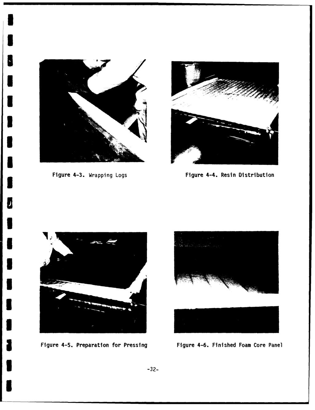
8 U LST OF FGURES 12-1 Mechanically Assisted Deposition of Broadgoods Composite Hull Aluminum Structure Baseline Armor System Selected Concept Nose Assembly Box Frame Assemblies with Transverse Beam Aft Assembly Engine and Driver's Bulkheads U3-9 Typical Splice Pattern Upper Hull sometric and Cross Section Upper Hull/Lower Hull Joint Upper Hull Tolerances Cross Section of Wrapped Foam Core "Log" Aft Assembly Joint Lower Hull Section Fabrication Sequence Lower Hull Test Mold Wapping Logs Resin Distribution Preparation for Pressing Finished Foam Core Panel nside of Upper Hull Tool Upper Hull, Outer Skin Ready for Cure Foam Core nstallation Lower Hull Mold Starting nner Skin Layup Preparation of Corners Placement of Floor Foam Box Frame Fitup Completion of Bondline Cure Preparation of Bagging and Cure vi
9 1 5-1 Joint Doubler Extension Racking Stresses Predicted for Modified Joint Design Upper Hull Ready for Trimming Trimming Operation Trimmed Section Trimmed S etion Trimmed Upper Hull Lower Hull nner Skin Trimmed Suspension Mounting Areas Upper Hull Skin Repair U 6-9 njection of Adhesive Nose Assembly Attachment Trunion Mounted Hull Tile Cure Preparations Completed Composite Hull Completed Vehicle Sensor Locations Vibration Frequencies Noise Comparison Hull Rigidity Tests Floor Surface Survived in Good Shape Sponson Surface--Has Worn Off Of Paint But Shows No Exposed Fibers Trimmed Edge of Cargo Hatch Opening--No Visible Deterioration Roof Beam--Bond Show No Degradation Torsion Bar Access Hole--Shows Rusted Steel Components Front Left Lifting Lug--Bolt Torques Show No Measurable Compressive Creep in 18 Months Mounting Hardware on Roof--Shows Signs of Hard Use But Remains Solidly Mounted Right Rear Tile Area--Aluminum Shows Heavy Gouging From Captive Rocks. Urethane Coating is Scraped Off But No Peeling Tendency is Evident v vii
10 Track Area--Excellent Abrasion Resistance From Urethane Coating on Tiles...71 U U U viii
11 LST OF TABLES 3-1 Criteria for Resin Selection...11l 3-2 Normalized Test Data Relative ndices Weighted ndices Materials Summary Vinylester Prepreg Resin Material Weight and Center of Gravity Hull Weight Estimate Vinylester Gel and Cure Data Vacuum Test Results nspection Summary, Upper Hull nspection Summary, Lower Hull Torsion Test Deflection U8-1 Estimated Cost for Manufacturing Process Development Estimated Unit Production Cost of Composite Hulls Labor and Material Break-own Basis of Composite Materials Estimate i
12 EXECUTVE SUMMARY This document is FMC's final report on the first program to successfully demonstrate the technical feasibility of using fiberglass-reinforced plastic (FRP) composite materials in the construction of a combat vehicle hull. FMC's Advanced Systems Center, San Jose, CA performed the work for the David Taylor Research Center (r-rc) under Contract N C The Contracting Officers Technical Representative (COTR) for this contract is Mr. Richard Swanek. The FMC project manager is Mr. A. L. Foote. Program results provided strong support for anticipated advantages of significant weight reduction, improved ballistic protection and lower life cycle costs through use of the composite materials. These advantages are expected to establish a solid foundation for work pioneered by DTRC in developing a high waterspeed technology demonstrator. The M113A1 personnel carrier was selected for this demonstrator to minimize new design problems and to provide efficient logistics support throughout the testing phase. Accordingly, the design should not be expected to demonstrate the weight savings potential for composite materials when used in a custom design based on its unique features. The vehicle has successfully completed endurance testing a+ the Amphibious Vehicle Test Branch, Camp Pendleton, California. The test program included over 740 hours and over 10,000 miles of rigorous driving.!! 3 Throughout the test period, no preventative maintenance was required for the composite structure, tile or abrasion coating. There were no tiles lost or loosened during the test period and the abrasion coating provided to protect against track slap performed very well. The vehicle showed significantly reduced noise levels in the driver's compartment and crew area during tests at FMC. This amounted to up to 10 db in some cases, and averaged 4.3 dba in the crew area and 3.0 dba in the driver area. x x
13 ABSTRACT Lightweight composite hulls are needed for possible use on future amphibian vehicles. This contract required the design, fabrication, and testing of a composite hull vehicle. The activity reported herein includes documentation of the vehicle design, and design and fabrication of fifteen test panels of the proposed sidewall construction. This report describes vehicle fabrication and compares weight and cost relative to a similar, aluminum-hulled vehicle. The report recommends materials improvements, gives selection criteria, and documents materials testing. Also included is a finite element analysis providing structural evaluation on the effects of given vehicle loads and tile attachment stresses, and a vehicle repairability study. Fabrication, inspection and testing activities are summarized, along with results of testing performed at the U.S. Marine Corps Amphibious Vehicle Test Branch, Camp Pendleton, California. 3 This work supports both the feasibility and use of composite hulls for tracked amphibious vehicles and recommends the continued development of composite hulled amphibian vehicles. xi
14 1.0 NTRODUCTON This report covers activity under Phase and of Contract N C-0024, "Design, Fabrication, Testing of Composite Hull for Tracked Amphibious Vehicle." FMC successfully completed this effort with subcontract support from Owens Corning Fiberglas under a cost plus fixed fee contract for David Taylor Research Center (DTRC), Bethesda, Maryland. The program includes design and fabrication of the FMC composite hull M113, a precursor waterspeed to a high amphibian vehicle technology demonstrator in the Marine Corps Surface Mobility Program (SURFMOB). The SURFMOB program is directed toward developing the technology necessary to demonstrate a practical, high waterspeed (20 mph or greater), amphibian vehicle system. Overall objectives of the SURFMOB program include the following (in order of priority): High waterspeed Reduced component weight mproved armor protection and survivability * mproved offensive capability and land mobility 5 mproved affordability, reliability and maintainability The SURFMOB program demonstrated fabrication and full-scale vehicle testing of component hardware. One pivotal subtask for this program was to demonstrate the hardware feasibility of a compnsite hull. The contract demonstrated tie feasibility of using lightweight reinforced-plastic (RP) hulls on future amphibious vehicles. * Contract line items for this contract include: gcln Design of one RP hull 0001 * Design O001AA * Test panels O001AB Fabrication, testing of one RP hull 0002 Final design, development and fabrication experiments 0002AA * Fabrication and outfitting O002AB Test panels O002AC Services to support government testing O002AD Work tasks subcontracted to Owens Corning Fiberglas included: * Mold design and fabrication * Hull layup 1 Materials studies, tests and miscellaneous support -1-
15 3 2.0 PRELMNARY NVESTGATONS Concurrent with Phase design activity, FMC conducted preliminary investigations in seven areas related to composite material selection and improvement: Materials properties determination Materials improvement Fabrication methods study Ceramic tile sizing and fastening study Structural analysis Repairability study * Materials samples verification 3The goal of these studies was to provide the necessary foundation for successfully demonstrating composite materials in the demanding environments of an amphibious combat vehicle. n each case, the studies focused on composites that would be useful for hull structures, as opposed to components or other combat vehicle applications. The specified hull material was a fiberglass-reinforced plastic (FRP) made from E-glass woven roving, weighing 24 oz/sq yd, with a resin matrix selected by FMC. Composite thicknesses were specified to be 0.75 inch in the sidewalls, 1.25 inch in the roof and 1.00 inch in the floor. Vertical surfaces were to be covered with high-purity (94% A ), 0.5-inch thick alumina tiles. 2.1 MATERALS PROPERTES STUDY The materials properties study documented physical properties of the structural composite for the design and fabrication phases of the program. Preliminary design properties were identified early in Phase. At that time, fabrication techniques had not been specifically identified; consequently, these preliminary design properties have been replaced with actual design properties which are listed in Section 4.5. Catalog data sheets, describing the nonmetallic structured materials used in the hull are contained in 3 Appendix A. 2.2 MATERALS MPROVEMENT STUDY 3 The goal of the materials improvement study was to upgrade and/or verify candidate materials in the following areas: m Noncombustibility Resistance to decontamination agents Resistance to water absorption : Resistance to environmental factors Resistance to chemicals * Resistance to thermal effects * Resistance to abrasion Repairability Only the most severe of these conditions were chosen for verification testing. Appendix B-1 summarizes the results of the Phase materials improvement study. -2-
16 3 2.3 FABRCATON METHODS STUDY We initiated a study to select the most appropriate method for manufacturing 1,000 composite hulls over a 3-year period. This study addressed the following topics: * Mechanical deposition of preimpregnated broadgoods (bulk fabrics with particular cured resin applied) * Single-part tape winding * Double-part tape winding 1 Special processes associated with a spaceframe design approach The study also addressed the selection of equipment to cure composite structures and the effect of various cure cycles. t described the recommended fabrication process and provided a production cost estimate and production schedule. As a result of this investigation, mechanical deposition of broadgoods, as shown conceptually in Figure 2-1, was selected to fabricate the production hulls. V 3 Figure 2-1. Mechanically-Assisted Deposition of Broadgoods 1 This mechanically-assisted deposition process delivers preimpregnated broadgoods to the mold surface. A ceiling gantry supports the material delivery -3-
17 1 head which moves with three degrees of freedom. This process offered three 3 manufacturing advantages: 0 Precombining resin and reinforcement materials results in a more easily handled, consistent material for deposition. * Applying broadgoods improves the deposition rate which exceeds other automated processes such as filament winding or tape laying. * Easily starting and stopping the process removes many obstacles encountered in tape winding. Some manual operations during material deposition are considered unavoidable, chiefly as a result of hull shape complexity, the nature of the hull wall construction and the limited production quantities. Results of the fabrication methods study are included in Appendix B CERAMC TLE SZNG AND FASTENNG STUDY Short-term goals of this study were: nvestigating the feasibility of attaching very hard, high-modulus ceramic tiles to a relatively low-modulus, composite substrate, dentifying an adhesive for tile mounting to obtain an optimum ballistic performance of the combined tile/composite system 3 This study's scope was limited because a rigorous optimization of tile size and fastening methods would require extensive operations research and ballistic testing, both of which were beyond contract requirements. To minimize effects of modulus mismatch without using a thick elastomeric potting adhesive, which might introduce questionable ballistic effects, a tile dimension of reverse 2 inches x 2 inches was selected. Although not as efficient ballistically as larger tiles, this size tile provides better multihit protection and will work successfully with a much wider range of adhesives than larger tiles will on a low-modulus substrate. Because most of the above considerations were not quantified during this study, we recommend conducting a more complete tile size optimization study in the future. 2.5 STRUCTURAL ANALYSS 3 FMC performed finite element analyses (FEA) on the reinforced plastic hull for all load cases. The analyses included in-plane stress and strain, out-ofplane bending, normal deflections and curvatures, stress resultants and stress from thermal expansion mismatch. A detailed description of the FEA model is included in Section Appendix C summarizes the design loads. meet these load requirements. m -4- Appendix D contains design FEA to
18 3 2.6 REPARABLTY STUDY A repairability study verified the availability of suitable repair techniques for the selected design concept and materials. A copy of this study is included in Appendix B MATERALS SAMPLES VERFCATON n accordance with contract requirements, FMC submitted 15 test panels of the preferred design structure (with tiles attached) for government testing. Three different protective coatings were applied: e Coating 1 (5 panels) -- Carbomastic 15, high-build aluminum epoxy matrix * Coating 2 (5 panels) -- Carboglass 1678, flake glass polyester * Coating 3 (5 panels) -- Kevlar 9.6 oz/sq yd cloth/epoxy No reports on test results of these panels have been received. U -5-

19 3.0 DESGN Two primary objeccives of this contract were: Develop and demonstrate the technical feasibility of composite materials in hull construction * Quantify possible weight and cost savings The design developed for a composite hulled vehicle, shown in Figure 3-1, demonstrates the feasibility of composite materials for use in amphibious 3 tracked vehicles.,-'n BQuantifying possible weight savings was implied rather than demonstrated because of M113 design constraints and because improved ballistic performance was implicit in the design baseline. These requirements allowed very little design flexibility which could be directed toward weight savings. A preliminary weight study which shows potential areas for future weight savings is included in Appendix E. Similarly, cost savings realized from substituting advanced materials in a "metal" vehicle design were also implied but not demonstrated. Actual weight and cost savings from composites can be better quantified when a vehicle hull is designed from the ground up to take maximum advantage of composite materials. 3 Our design approach with this "materials demonstrator" vehicle was to aggressively pursue the use of fiber-reinforced plastic (FRP), but keep design margins conservative enough to ensure survival of this first-of-a-kind vehicle through a rigorous, long-term test program. Consequently, minimizing weight and cost on this specific design was not a direct objective. * -6- Figure 3-1. Composite Hull
20 3.1 CONCEPT DEVELOPMENT Although first-article costs and weight reduction were not primary considerations, we directed our overall design towards meeting mission requirements by using practical, economical production methods. This design goal ensured that successful completion of field testing would result in both qualifying selected design features, and verifying materials and fabrication processes. Our preliminary investigation selected mechanically-assisted deposition of broadgoods as the targeted production technique. This proven method provides high production rates, as well as design and layup flexibility. Other techniques, including automated winding methods and/or pultrusion of sections or stiffener struts for hulls, could also provide very low-cost production in a wide range of production quantities. 1 However, these methods would be much more design restrictive. To produce the 1,000 units contemplated in this contract, we determined the most appropriate plan was to develop a production capability that could be backed up by an essentially manual layup process using preimpregnated composite materials. The technique envisioned would emphasize mechanization of material delivery and layup rather than automation. m Contract-Directed Design Requirements Design requirements imposed by the contract included the use of M113A1 components as government furnished equipment (GFE) and selected dimensional and material baselines. These requirements included the following: 3 * Configuration and envelope: Same as M113A1 vehicle * Fiberglass reinforcement: E-glass 5 Ballistic tiles: 0.5-inch-thick alumina (94% A ) m Baseline FRP thicknesses: 1.25 inch (top); 0.75 inch (sides) * Floor structure thickness: Dependent on material selection (1.125 inch, aluminum; 1.0 inch, composite) n addition to these specific design requirements, the contract also identified the hull loads. n some cases, FMC increased the specified design loads to better ensure survivability throughout the field test program. Among the increased design loads were the impact loads on the drive sprocket and some inertia loads. All loads are summarized and illustrated in Appendix C, with FMC additions clearly indicated. / Krolewski, Susan, Gutowski, Timothy, Effect of the Automation of Advanced Composite Fabrication Process on Part Cost, SAMPLE Volume 18, N. 1, October 1986, pp
21 Approach in accordance with the overall design approach to "aggressively pursue the use of FRP," FMC set guidelines for assigning materials to various hull structures. These guidelines specified that the aluminum structure in the hull should be retained only for reaction of high point loads and/or structural continuity. As a result, the following aluminum assemblies were retained in the new vehicle design: * Nose assembly a Boxframe assemblies and connecting transverse beam 0 Aft plate assembly * Engine and driver's bulkheads Together, these structures amounted to one-third of the overall weight of the composite hull. Figure 3-2 illustrates the aluminum structure. Other metal components were either installed as GFE (e.g., rear ramp, hatches) or presented minimal weight impact (incidental brackets and inserts). n future designs, many of these metallic assemblies and components may be replaced by composites, depending on functionality, cost and repairability. Assembly Engine Bulkhead Transverse Beam Drivers Bulkhead Nose Assembly Box Frame Assemblies Figure 3-2. Aluminum Structure Tradeoff Evaluation The basic approach in our tradeoff evaluation included replacing aluminum with FRP on the floor, sides, roof and left glacis plate of the vehicle. t required several design tradeoffs based on less than complete performance data, particularly in the ballistic area. Three of these tradeoffs are discussed in the following paragraphs. -
22 Side Panel Design Tradeoff. The design tradeoff for the side panel can best be described by referring to the baseline armor system specified in the contract and illustrated in Figure 3-3. This illustration shows the application of ceramic tiles to the outer surface of the composite material. The purpose of these tiles is to shatter the armor piercing rounds before they reach the more resilient composite. The bond design criteria for optimum ballistic performance of the tile-to-frp attachment is not yet completely defined. Experimental data 2 prepared for the Advanced Research Projects Agency (ARPA) indicated that ceramic tile is most effective when the substrate provides a certain minimum stiffness. Once the rounds are shattered, the fiberglass composite works most effectively to capture fragments by delamination and panel deflection. The ability to provide a "rigid" support for the tiles--coupled with more flexible (i.e., higher deflection) characteristics during composite penetration--should be an objective for future development work. Alumina Tile (AL ) 94% Pure Bonding (Potting) Material 5FRP Hull Structure (and Tile Substrate) L 5 Single Hit Versus Multiple Hit Tradeoff. Another ballistic tradeoff is ceramic tile size to defeat single and multiple hits. Tiles of decreasing cross-sectional area from approximately 6 inches suffer a relatively rapid decrease in ballistic efficiency for the expected threat projectiles. On the other hand, multiple hit performance of plates incorporating large tiles is considerably degraded compared to the same plate with smaller tiles. Thus, single and multiple hit performance of a ceramic tile cannot be independently optimized. Figure 3-3. Baseline Armor System Tile Versus Composite Modulus Tradeoff. Coupled with ballistic optimization compromises, inherent structural problems of elastic modulus mismatch exist between the tile and composite materials. The modulus for the alumina tile was 41x10 6 psi, whereas that of a typical FRP panel was 3x10 6 psi. Accommodating this modulus mismatch requires a compliant mounting between the two materials to absorb any strain differential. The proper compliance can be 2/ Wilkens, Mark L., "Third Progress Report of Light Armor Program," UCRL-50460, July 9,
23 * obtained by a combination of low modulus bonding material and increased thickness of the bonding material. However, as postulated above, too soft a tile support can degrade tile performance ballistically. m Selected Concept Early in the tradeoff review, FMC decided to use sandwich core construction on the demonstration vehicle. FMC selected this construction to ensure adequate panel stiffness. This solution minimizes the operating problems for major structures and components attached to the hull and reduces the stiffness mismatch between ceramic tiles and composite panels. Figure 3-4 shows a cross section of the selected concept. compsiterigidity m Ceramic Tile Foam Core Sandwich Construction for High Strength and Stiffness and Light Weight Typical Hatch Closeout (avoids exposed core material) Aluminum Channel Upper Hull Upper to Lower Hull Joint Thick Sandwich Solid Floor Section to Aluminum Box Provide Torsional Frame Assembly to the Hull (Box BoweaHu) Lower Hull Figure 3-4. Selected Concept The sidewall sandwich construction provided approximately 19 times the flexural rigidity of the same FRP thickness of solid laminate design. The foam-filled subfloor space provided additional torsional resistance to the vehicle sponson cross area used section. a solid To composite conserve construction. interior space, the small panels in the 3.2 MATERALS Resin Selection A two-step approach was used to select the resin: Step 1: Select resin systems having process parameters (e.g., pot life, toxicology) that were consistent with the manufacturing parameters (e.g., layup schedule, cure time). -10-
24 m o Step 2: Conduct a detailed cost-performance tradeoff using four resin systems selected in Step 1. Step 1: Resin System Selection. We considered many resin systems during the initial screening, including polyesters, vinylesters, epoxy resins, and phenolics. Early on, it became apparent that the key limiting factor was processability. The thick section of the M113 walls renders the use of resins, which cure with high exotherms or evolve volatiles, as highly impractical. Other considerations were toxicology and availability of materials in the U.S. in production quantities. Additional considerations were functional requirements for materials improvement dictated by the RFP and collected from vehicle operating parameters (i.e., coolants, fuel, lubrication, environmental). m Candidate resin systems were selected for more detailed cost/performance tradeoffs. From this analysis, we chose the following resin systems for more detailed comparison: * Owens-Corning Fiberglas (OCF) polyester E701 f OCF flexibilized polyester E737 * Dow vinylester Derakane Shell epoxy Epon 828 All systems were reinforced with 70% by weight OC24-54-P-475T, 5 X 4, 24-oz, E-glass woven roving. Step 2: Cost-Performance Tradeoff. The second step in the resin selection process was a detailed examination of performance requirements. A series of performance tests were conducted to identify material properties, which were then assigned the weighting factors shown in Table 3-1. Table 3-1. Criteria for Resin Selection PERFORMANCE CR1 ERA WEGHT FACTOR Tensile Strength RT/190 F 3/3 Tensile Modulus RT/190 F 3/3 Tensile Elongation RT/190 0 F 3/3 Apparent Horizontal Shear Strength 6/5 RT/190 F Bearing Strength 5 Shear Modulus, Fraction (i90f 6 Retention, DMA Rheomtry RT NBC Waahdown Resistance STB/18 HR 6 RT2 3 0S2/24 SR F 3 3 Cost (2/Pound) ii -11-
25 m m Following this, we fabricated composite test panels using each of the four resin systems and tested the parameters established in Table 3-1. Table 3-2 shows the averages for each of the four systems (all values normalized for 70% by weight glass). Table 3-2. Normalized Test Data SHORT STB WASHDOWN TENSLE TENSLE TENSLE BEAN BARNG DNA RHEOMETRY RESSTANCE COST TOTAL MOD4JLUS STRENGTH ELONGATON SHEAR STRENGTH SHEAR MODULUS FLEXURAL STRENGTH FRACTON WEGHTED (MS) (KS) () (SK) (KS) FRACTON RETENTON FRACTON RETENTON (COST/) NDCES R.T. igoof R.T. 190F R.T. 190OF R.T 190OF R.T 190OF/r.T 16 HR/R.T. COMPOSTE* [WTHOUT COST] mndc PROPERTY ES $1.00!SCALNG FAC TOR [1 1FC)10 51 [411 E POLYESTER POLYESTER VNYtL ESTER j EXPOXY Next, we selected a value for each parameter to represent an "ideal" laminate. Then, a series of relative indices (Table 3-3) was obtained by dividing the values of the various measured properties in Table 3-2 by the corresponding ideal property index. Table 3-3. Relative ndices TENSLE TENSLE TENSLE SHORT BEAN BARNG A RHEONETRY STB RESSTANCE WASHOWN COST TOTAL MOULUS STREGTH ELONGATONE SO STRENGTH SHEAR MOULUS FLEXURAL STRENGTH FRACTON WEGHTED (NS) (KS) (Z) (SK) (KS) FRACTON RETENTON FRACTON RETENTON (COST/#) NDCES m ARBTRARY JT FR.T. 1ROF R.T F R.T 190OF R.T 190OF/R.T 16 HR/R.T. COMPOSTE* [WTHOUT COST] PROPERTY $1.00 NDCES SCALNG FACTOR _ [41] (FC) E-701 POLYESTER POLYESTER VNYL UXPOXY i
26 To establish the relative performance of the four systems, the relative indices from Table 3-3 were multiplied by the appropriate weighting factors in Table 3-1. The resulting weighted indices are shown in Table 3-4. When these indices were added together, the resulting sum'gave the overall performance ranking for each system. Table 3-4. Weighted ndices SHORT STB WASHDOWN TENSLE TENSLE TENSLE BEAN BARNG DNA RHEOMETRY RESSTANCE COST TOTAL MODULUS STRENGTH ELONGATON SHEAR STRENGTH SHEAR MOOULUS FLEXURAL STRENGTH FRACTON WEGHTED (T ) (KS) () (SK) (KS) FRACTON RETENTON FRACTON RETENTON (COST/#) NDCES R.T.PER OOF4 R.T. 190OF R.T. 1g0OF R.T 190OF R.T 190OF/R.T 16 HR/R.T. COMPOSTE- [WTHOUT COST] ~ARBTRARY PROPERTY $1.00 NDCES SCAL114G CFACTOR (411 E-701 POLYESTER [37.97] [35.33] y o48.81 [39.51] ESTER EX XY [37.97] n practice, epoxy preprog will be used as the raw material. The cost of prepreg is -$6.00/lb. This modifies the weighted cost fraction to 1.7 rather than 7.3. This change should not modify weighted performance (37.97] but does modify total cost weight indices to UAll four resin systems ranked very closely to each other and to the ideal laminate in overall score. For this fabrication study, FMC selected Derakane as the best of the four resin systems. However, due to widespread acceptance of epoxy resins for structural composites, we proceeded into the Phase fabrication study with two resin selections, Derakane and an epoxy system. To test the merits of the two resins, FMC used the epoxy prepreg on the lower hull and the Derakane on the upper hull. This approach is discussed further in Section Core Material Selection n sandwich structures, the primary function of a core material is to separate the facings and carry shear and compressive loads through the sandwich thickness. deally, the core should be a rigid, lightweight material capable of delivering uniformly predictable properties in whatever environmental conditions the vehicle performs. Four candidate materials were considered for -13-
27 core construction: reinforced plastic, honeycomb, wood and foam. These materials were evaluated on the basis of the following performance requirements: Shear strength * Compressive strength Maximum service temperature Moisture resistance Flammability Additional nonperformance-related availability, processability factors and density. were The also considered, results of this tradeoff such as cost, study are summarized below. Reinforced Plastic. We identified and evaluated specialized geometries of reinforced plastic, such as nested tetrahedrons, that could be vacuum-formed or compression-molded. At present, the performance of these geometries is not well documented because the concepts are still in the developmental stage Honeycomb. Honeycomb construction was rejected because it retains water. When a honeycomb laminate is damaged ballistically, water can enter the core and reside in the honeycomb cells for long periods, degrading the structure. The high costs of honeycomb construction also make it less attractive than other core materials. Wood. End-grain balsawood is widely used to build boat hulls. Select grades of this material proved an excellent core material candidate due to its ease of use, good durability, high compressive strength, high modulus and overall shear strength. Accordingly, a section of balsa core was included in the prototype hull and evaluated for long-term moisture resistance, face-to-core bond integrity and susceptibility to biodegradation. i Foam. Several foam materials in the density range of interest were evaluated, including ABS, cellulose acetates, epoxies, phenolics, polycarbonates, polyurethanes, polyvinylchlorides and polyimides. Only polyimide foams had sufficient strength at high temperatures. Accordingly, the foam selected for the composite hull core was a polymethacrylimide (Rohacell 110). This closedcell, high-strength structural foam is a superior thermoplastic that offers excellent performance at high temperatures. This noncombustibility material is resistant to chemicals and moisture, has a reasonably good low burning ratio and is readily available. ts weight-to-volume ratio was also good (6.9 lb/ft 3 ). Appendix A-5 gives the physical properties and performance characteristics of the selected foam material.
28 Material Properties Key materials chosen for fabricating the composite hull are summarized in 3 Table 3-5. Table 3-5. Materials Summary m Appendix Material Function Location Material Type Section Composite Resin Upper hull Derakane 411 VE A-1 Matrix Prepreg m Composite Upper and 24 oz WR E-glass A-2 Reinforcement lower hulls Fiberglass 1 Composite Resin Lower hull DGEBA*/Dicy**Epoxy A-3 Matrix Prepreg m Tile Armor Sides 94% d A A-4 * Core Material Sides, Top, Floor Polymethacrylic- A-5 3 imide rigid foam m * Core Material Front (Upper Balsa Wood A-9 Glacis) 0 Abrasion Wear Sponsons Polyurethane rubber A-1O Surfaces 1 Adhesive As designated Urethane Prepolymer A-11 in text 3 Film Adhesive As designated Modified Epoxy A-12 in text. Diglycidyl Ether of Bisphenol - A ** Dicyandiamide m i _15-
29 Materials of the vinylester prepreg resin (Al) developed for this application are shown in Table 3-6. Table 3-6. Vinylester Prepreg Resin Material 3OUTER SKN Materials Parts By Weight NNER SKN Dow Vinylester FMC Xyrex 4.0 Nyacol APE Mini Fibers Short Stuff 1.5 Eastman Hydroquinone Lucidol Benzoyl Peroxide 0.23 T-Butyl Perbenzoate 2.31 i Materials Parts By Weight Dow Vinylester FMC Xyrex Anzon Antimony Trioxide Mini Fibers Short Stuff 1.5 Eastman Hydroquinone Lucidol Benzoyl Peroxide 0.23 T-Butyl Perbenzoate DESGN AND ANALYSS Aluminum Structure Design Aluminum structural assemblies were retained in the vehicle design to react high point loads or to provide structural continuity. The retained aluminum structures consisted of the following: * Nose assembly : Boxframe assemblies and transverse beam 0 Aft plate assembly Engine and driver bulkheads Nose Assembly. This welded assembly (Figure 3-5) supports and helps align the drive train and engine, and also serves as the mounting for the drive sprockets. The primary structural element in the nose assembly is the m lower glacis plate which has a thickness of 1.5 inches S
30 , Fiur 3-5 Nos Assmbl Figure 3-5. Nose Assembly The nose assembly is connected to the upper and lower hull assemblies by bolted lap joints and butt joints and weighs 873 lb Box Frame Assemblies. The box frame assemblies with an interconnecting transverse beam for engine support are shown in Figure 3-6. These assemblies connect to the nose and aft plate assemblies. They provide a rigid support for all roadwheel mounts and most of the suspension system components. The frames are fabricated from open sections of extruded aluminum, welded together longitudinally into a closed, box-shaped beam. Vertical and horizontal extensions from the box shape distribute loads to the composite sidewall and floor laminates. The outer beam surface (1.25 inches thick) provides ample depth for the large inserts on the roadwheel mounts. To ensure a good bonding surface for contact with the composite material, these assemblies were anodized with hot phosphoric acid and painted with epoxy primer. The weight of the completed box assemblies (over 450 lb each) could be significantly reduced with additional design time. a Figure 3-6. Box Frame Assemblies with Transverse Beam -17-
31 Aft Plate Assembly. The aft plate assembly (Figure 3-7), consisting of a 1.5-inch-thick aluminum plate with welded support bars, supports the aft edge of the composite skins. A heavy, triple-clevis hinge supports the rear ramp. Both the ramp and aft plate should be investigated for possible replacement with FRP material. The aft plate assembly, without ramp, weighs approximately 590 lb. Figure 3-7. Aft Assembly ' Bulkheads. The engine and driver's bulkheads (Figure 3-8) separate the crew and engine compartments. These load-bearing structures, collectively weighing 33.6 lb, are considered viable candidates for replacement with composite bulkheads, but the weight payoff is obviously limited. 0 0 l0 Figure Engine and Driver's Bulkheads

32 3.3.2 Composite Structure Design The composite structure consists of an upper and a lower hull assembly fabricated separately to facilitate the layup, and to permit easy mold release from tooling with no undercuts and minimal draft angles. We considered various designs during the preliminary design phase. The primary candidates included a single laminate semi-monocoque shell and a foam sandwich. To generate more complete field performance data, we used both these structural configurations for constructing the composite hull. A foam sandwich with 1-1/2 inches of high temperature polyimide foam was used in the roof and side panel sections, providing these areas with a panel stiffness approaching that of aluminum. For the floor section, a 6-inch foam slab with cutouts for torsion bars and bilge pumps was used. To accommodate inside equipment dimensional requirements over the sponson area, solid laminate composite construction was used at these locations. For the hull's fabrication, we used E-glass, woven roving preimpregnated with a vinylester for the upper hull and an epoxy resin for the lower hull. Broadgood plies of this preimpregnated (prepreg) material were laid up orthogonally to the vehicle axis with butt joints at the edges of each ply. To avoid localized weakening, successive layers used staggered splices for the total hull construction. A typical staggered splice pattern is illustrated in Figure nch Overlap 3 Mi. Between Plies Butt Plies at LSplices -Max. Gap nch Figure 3-9. Typical Splice Pattern Upper Hull Design. The upper hull is essentially a canopy characterized by large flat sides and a broad roof (Figure 3-10). Ceramic tiles are bonded to the exterior of the sides and cutout areas are provided in the roof for hatches, vents and radio equipment. Since the upper hull is subjected to lower, distributed stress levels, it features a ballistically driven design of a relatively constant cross section. The sidewall skins are 0.38 inch thick with a 1.5-inch foam core between them. A ballistic cap provides added composite thickness of 0.88 inch in the roof for protection against fragments. This ballistic cap is continued around the roof edge to butt with the top edge of the ceramic tiles on the sidewall. A composite roof beam replaces the aluminum roof beam in the original M113A1 design
33 -- Ballistic Cap 3 Composite Roof ' Beam 3 Figure Upper Hull sometric and Cross Section The upper hull/lower hull joint is a 900 butt configuration with bolted and bonded epoxy prepreg doublers extending from approximately 6 inches above the joint to the bottom of the lower hull sidewall (Figure 3-11). A 1.5-inch aluminum U channel is used to terminate the upper hull foam core and provide a structure for bolting. The accurate placement of the U channel in the upper hull is vital to the fitup of the upper to lower hull joint assembly. Theplacement vertically was referenced to the mold line of the inner surface of the outer skin roof (Figure 3-12). The tolerance on this dimension is The separation of the upper hull sidewalls is toleranced at inchei due to the more difficult layup control problems involved and the inherent flexibility of the separation dimension during assembly. S0 FOAM-_, COMPOSTE DOUBLER ALUMNUM CHANNEL Figure Upper Hull/Lower Hull Joint -20-
34 _0.030 ± 0.25 Figure Upper Hull Tolerances The foam core consists of 1.5 inch x 1.9 inch "logs" of high strength, polymethacrylicimide (PM) foam, wrapped with vinylester resin impregnated fiberglass (Figure 3-13). The purpose of the wrapped logs is to restrict any progressive tensile or shear failure within the core material. To provide an improved bond strength between the foam anid the fiberglass, all surfaces of the foam were modified by "needle rolling." This procedure uses a roller with tapered needles, 4mm long and 0.6mm wide at the base to increase the effective surface area and the resin penetration during the bonding operation. The spacing of the needle pattern in the foam was 0.2 inch x 0.2 inch. m FOAM "LOGS, RESN MPREGNATED 1.5-in. X 1.9-in. FBERGLASS FABRC Figure Cross Section of Wrapped Foam Core "Log" 3 To evaluate an alternative core material, we substituted an end grain balsa core for the polyimide foam core in the upper glacis plate in front of the driver's position. This core material features more than a fivefold increase in compressive strength (2400 psi versus 427 psi) compared to the foam material; but it is 67% heavier than the foam (11.5 lb/ft 3 versus 6.9 lb/ft 3 ). -21-
35 Closeouts were used in the sandwich construction design to efficiently 5 transfer loads to adjacent structures and to protect the core material from exposure. A typical closeout and associated joint for the upper hull is shown in Figure AOHESYE/SPALANT. COMPOSTE AM AFT ASSEMBLY, Figure Aft Assembly Joint Lower Hull Design. The composite lower hull section is shown in Figure The assembly consists of a combination of sandwich and semimonocoque construction. The same fiberglass fabric is used on upper and lower hulls but the lower hull uses an epoxy resin matrix. The sandwich construction is maintained in the lower sidewall area in the same proportions as the upper sidewall area. The sponson is designed as a solid composite laminate to preserve the necessary internal space for mounting the personnel heater. 3Figure Lower Hull Section Lower hull thicknesses include: 1 Outer skin inch thick in the sidewall and.75 inch thick in the floor area 0 nner skin--.38 inch thick in the sidewall and.25 inch thick in the floor area * Foam core in the sidewalls is the same as the upper hull. Floor foam is 6.5 inch thick. t is adhesive bonded between the box frame assemblies and -22-
36 3 the inner and outer floor surfaces to form a rigid structure to provide added torsional rigidity to the vehicle cross section Analyses Stress Analysis 3 The composite sandwich hull structure is designed to sustain design limit loads without yielding in the metallic components and without failing when subjected to ultimate loads. The ultimate loads are defined as the limit loads multiplied by a safety factor (SF). For the composite components, a safety factor of 2 is used; for all metallic parts, a safety factor of 1.5 is used. The maximum stresses (f) are compared to the material allowable properties (F). The equation for a positive margin of safety (MS) for all component stresses is given below: MS= 3 F -1 SF x f Where MS = Positive margin of safety SF = Safety factor f = Maximum stresses F = Material allowable properties The generalized hull stresses were calculated for the load conditions in Section 2.3 using an ANSYS finite element program. Stresses in the fiberglass face sheets and foam core were calculated as mutually perpendicular in-planestresses (Sx and S ) and n-plane-shear stresses (Sxy) using ANSYS composite shell elements. Sresses in the aluminum components were calculated as equivalent von Mises stresses. Appendix D-1 summarizes the maximum stresses and deflections in both the composite and metallic components. This appendix includes all load requirements specified in the Statement of Work (SOW) and includes selected increased load cases (4 and 11) and one added load case (13), based on FMC field and test experience. n some cases, the loads are bounded by other specified load cases and, therefore, are not separately listed Tile Analysis. As shown in Appendix D-1, the outer skin stress is 3250 psi for all 23 load cases calculated. Maximum stress in areas covered y tile is 3000 psi. Additional stress occurs from thermal expansion effects due to the large difference between thermal expansion coefficients fiberglass/expoxy between prepeg (FG/EP) and alumina tile materials. For Appendix calculations, D-1 the tile layer is assumed to have zero stiffness. 3 Results of the tile thermal analysis are shown in Appendix D-2. Results from Cases C and D include effects of an imposed outer skin stress from Appendix D-1 results. Cases E and F include effects of severe bending of the outer hull's FG/EP sandwich plate (see Appendix D-3 for rotations and deflections). Case F, a limiting case, includes effects of both an imposed -23-
37 stress and bending deflection. All cases include additional stresses from large thermal expansion effects. Since the tile layer stiffness modifies the outer skin stress states listed in Appendix A (for which zero tile layer stiffness was assumed), the local stresses will change in the vicinity of the tile (FG/EP layer interfaces); these stresses are shown in Appendix B. Results indicate that even for the most severe case (Case F), which bounds all other cases, all FG/EP stresses are less than the ultimate strength of approximately 40 ksi. Case F represents a worst-case, extreme condition. The remaining, more typical cases predict large safety margins. Because, in practice, the tiles are enshrouded in an epoxy matrix of low stiffness, the actual epoxy and FG/EP surface stress will be somewhat lower than those predicted by the finite element (FE) model (which assumes no epoxy layer between tile and outer FG/EP skin). n assessing the temperature imposed on the FE model, the uniform temperature is to be added to the delta T temperature for the total temperature. For example, Case F temperature is = F Hull Analysis. All load cases specified in the SOW were input to the M113C FE model to obtain stress and deflection information. However, some loads were augmented to reflect more conservative estimates based on FMC design practice and field experience with the M113 vehicle. For example, a load case in the SOW defined a 42,000 lbf horizontal and 28,000 lbf 300 to the horizontal delivered simultaneously to the front been replaced sprocket. This loading by Cases 6 and has 7. The new loads, which are much larger than previous load levels, led to a front-end design with a built-in safety factor of at least two times over the prior load level specifications. A further example involves Cases 2, 3 and 4. Previously, 3g was applied to all concentrated and distributed masses on the hull. Concentrated masses (i.e., engine, transmission, transfer case) were loaded at their respective CG locations. Those loads were replaced by log down, 5g side and 8g fore-aft static loads which bound the dynamic accelerations. Design to these higher static loads led to a structure with a margin to withstand dynamically-induced force levels. Such force levels can occur, for example, when the vehicle track and suspension system hits a field obstacle while the vehicle is travelling at high speed. All twelve load cases specified in the SOW are bounded by the seven load cases defined below. The structural design of the composite M113 is based on the stress and deflection results obtained from the following seven load cases: CASE ,000 lbf up on the right-and side (RHS) front sprocket 3 CASE 2--10g down loading U CASE 3--5g side loading CASE 4--8g fore-aft loading CASE 5--50,000 lbf up on the first roadwheel m -24-
38 U CASE ,000 lbf horizontal (longitudinal) on the front sprocket CASE ,000 lbf up on the left-hand side (LHS) front sprocket These cases represent the seven "worst case" loads. Results for the FE runs are given in Appendix D-3. Rotations, deflections, forces, moments and stresses obtained at the sponson joint are summarized in Appendix D-3, page D-65. The quantity ROTX denotes the maximum in-plane rotation of the right-angle joint under load; Ty/TX denotes the maximum ratio of lateral to longitudinal maximum force on the joint, Sy is the maximum lateral deflection of the vertical side panel relative to the joint edge; Mx is the maximum moment about the joint longitudinal (X-direction) edge and S v is the maximum sponson (0.75 inch) outer lamina normal stress in the Y-direction. Shear stress (Sxy) and X-direction normal stress are also shown as are stresses within the foam core sandwich plate. (See Appendix D-3, page D-66 for the coordinate system.) Appendix 0-4 details the methodology used to design the sponson joint. The two-dimensional sponson joint geometry that was fabricated is shown in Appendix D-5, page Note that the monolithic horizontal sponson plate design is evaluated using the worst-load case joint rotation (Case 1, 100,000 lbf upload on the front sprocket). A rotation is computed from FE analysis for the total M113C model (Appendices D-3 and D-6). Twodimensional FE models of the joint are loaded with a force (or deflection) applied at point A (page 0-157) to produce that rotation. The internal joint stresses are then computed and structural modifications were incorporated to reduce stresses to acceptable levels. This was done by the addition of doubler plies (a and b, page D-155) of fiberglass/epoxy prepreg (FG/EP) to the outside and inside corners of the sponson Joint. Additional load cases were run that use the maximum loads, moments and/or displacements obtained from Appendix D-3, with corresponding boundary conditions to insure that the joint rotation load case bounds all other stresses computed for all other load cases. Additional stress and deflection FE calculation results are reported in Appendix D-3 for the two-dimensional joint using different types of limiting boundary constraints. The FE results indicate that the joint is structurally adequate. Loads used to produce the joint rotation are therefore sufficient to bound all other loads obtained from alz remaining load cases. Appendix D-4 provides further details of calculations performed to obtain moment distributions on the joint for the worst load case. These values are used in the analyses described n Appendix D-3. A joint section approximately 18 inches wide was fabricated for test purposes and subjected to the following tests: * Load-deflection runs in both up and down directions * Fatigue tests Design ultimate load 0 Strain-to-failure -25-
39 m m * Above tests are described in Appendix D-7. Test runs were made for the double sandwich joint configuration (Appendix D-7, page 0-184) while computations were made for both the double sandwich and horizontal monolithic FG/EP plate m joint configurations. A comparison of S shear stress indicates maximum stresses in the range of psi for both designs (Appendix D-4 versus Appendix D-5). Although test results were only obtained for the sandwich plate joint, the similarity of maximum stress values for both design (which are well below design maximums under the severest load conditions) implies an adequate margin of safety for 3 the monolithic plate joint design. To further verify the composite hull design and associated joint design, a series of load tests were performed on the as-built hull. These tests are summarized in Appendix 0-8. Two tests were executed: Test was a center top plate vertical load with four vehicle corner points resting on blocks; Test simulated a racking test for which a load was applied to the left rear top plate corner while the vehicle rested on blocks on the left front and right rear corners. The right front corner was vertically restrained from movement. Application of loads up to 5,000 lbf indicates small stress values for strain gages 2, 3, 5 and 6 located in the proximity of the joint (with a monolithic FG/EP horizontal sponson plate). Since the joint test stresses are well below design stress allowables for the full hull test, adequacy of the original joint design is demonstrated. Load tests further indicate (Appendix 0-7) that no failures occurred in any categories previously listed for worst-case loadings of the joint test specimen. The full hull test that si-mulated this loading further produced (extrapolated) stresses generally in the range of 3 computed results. Tests have been conducted on the FMC test track to examine the stress maximums on the M113C hull under dynamic loading conditions. The vehicle was driven over various obstacles in the lightly loaded and combat-loaded configurations. Strains were measured at key locations on the hull. These tests are described in Appendix H-i. An analysis of the stresses measured is contained in m Appendix D-9. The great majority of stress results obtained from tests are within FE predictions given in Appendix D-1. The only deviation occurs for a strain gage reading located in the proximity of the forward joint. n this case, measured stresses are higher than predicted but well below the ultimate strength of the FG/EP plates by a factor of at least 4. The explanation lies in the fact that local joint stress effects (i.e. bolt clamping stresses, adhesive bond stresses, drilled holes) alter the local stress beyond what the 3 FE model is capable of predicting, unless many elements are added in the joint region Weight and Center of Gravity (CG) The predicted and delivered hull weights and CGs are shown in Table 3-8. This table also shows the comparable values for an aluminum hulled vehicle. Results indicate that a reasonably good agreement between predicted and asdelivered values was achieved and that the overall comparison with the -26-
40 aluminum hulled M113 was adequate. Weight measurements used to define the asdelivered conditions did not include a driver. The driver's weight was calculated as 240 lb and added to the measured weight of 20,260 lb to arrive at the listed weight value. CG values were not adjusted for the driver's weight. Table 3-8. Weight and Center of Gravity Predicted Composite Vehicle Aluminum Composite Properties Vehicle Properties Vehicle Properties (as delivered) 3 Weight, lightly loaded (with 20,785 lb 20,500 lb 21,965 lb driver and fuel) Center of Gravity x (station line) y (buttline) z (waterline) During the fabrication and assembly process, various components of the composite hull were weighed to verify overall predictions of weight and CG: To define the actual weight of the completed hull as accurately as possible, we constructed Table 3-9 from a combination of known and estimated component weights. The aluminum hull, welded and machined, weighs 6646 lb. ~COMPOSTE Table 3-9. Hull Weight Estimate (FRP) CORE ALUMNUM TLE MSC. TOTAL NOSE 783(W) 783(W) AFT PLATE 590(W) 590(W) UPPER HULL 1774(E) 129(E) 67(E) 30(E) 2000(W) BULKHEADS 39(E) LOWER HULL 1220(E) 213(E) 997(E) 20(E) 2450(W) JONT DOUBLER 388(E) 388(E) ARMOR 30(E) 855(E) 885(E) ROOF BEAM 43(E) O(E) 53(E) MSC. MATERALS 1OO(E) 1OO(E) Weight in pounds, (E) - Estimated,(W) - Weighed 1-27-
41 * 4.0 HULL FABRCATON 4.1 FABRCATON SEQUENCE The aggressive design approach, including sandwich construction over most of the hull and integration of major aluminum structures with the lower hull layup, posed significant challenges to the fabrication effort. These design challenges were complicated by the development of a new resin system for the upper hull and schedule commitments that precluded the normal practice of making a full-scale test part from each of the molds prior to layup of the deliverable sections. To make the first try successful, we recognized that close coordination between the design and fabrication activities was required and a carefully planned fabrication and assembly sequence was mandatory. The fabrication sequence for the upper and lower hull sections is shown in Figure 4-. The following paragraphs describe the fabrication process. Upper Hull. First, the upper hull outer skin was laid up and cured on a male mold, producing a part shown in Figure 4-1a. Then, this outer skin was inverted and placed in a support fixture to permit the application of foam (Figure 4-1b) and the inner skin (Figure 4-1c). This sequence was selected to provide the most efficient layup of the outer skin which constitutes the bulk of the upper hull material. The inner skin is much thinner and more readily formed into the closeout patterns required around the foam panels. Lower Hull. The lower hull section was more critical in tolerance and more complex in configuration. The layup was completed on a male mold for the entire section. First, the inner skin was applied and partially cured (Figure 4-1e). Next, the foam was applied (Figure 4-1g). The outer skin was applied as shown in Figure 4-1h (the scuff plate application was postponed until later in the assembly process to permit interim machining access to the outer skin). After machining the upper and lower hull sections, the nose and aft plate assemblies were fitted and the hull assembly was completed (Figure 4-lj). 4.2 RESN DEVELOPMENT We used a vinylester resin, fire-retarded prepreg on the upper hull. t was supplied in roll form between parting films and had a reduced styrene monomer content to control the degree of tack which allowed placement and debulking in the required orientation. The resulting material did require storage under cooled conditions, and in this sense it was similar to an epoxy prepreg. Table 4-1 shows the 260OF gel and cure information for the two vinylester prepreg materials that were used in the upper hull. 3 Table 4-1. Vinylester Gel and Cure Data Lot No Mfg Date oF 150-Peak Peak Temperature /23/85 3:75 min 4:42 min F /28/85 3:06 min 4:05 min F -28-

42 U Upper Hull Fabrication Sequence Lower Hull Fabrication Sequence...- S~. V -. 't~' /.**~1...OOo ~...,~:,/ ~ - ~~&o4~ 0...~....,~0. -,. CCO~.. " A 0 ~ 4..CO **'.*94,... A., 1'09..CO. -. S.0~ C o.0 A.C~..0~A,.,.. 0 C'..~. C22'A40AA~.44~C0:., C'? / CC" C..oO...,.. 4; A.S ~C. - ~ o/.~ -~.# U-A ~.o.,~,40. -, - ''",~ ~C~.?7 4.~ ~'vr SA ".4".0,. 05..~. ;.00C~..0.,.\ ~. Figure 4-1. Sequence
43 3 The lower hull material was an off-the-shelf epoxy prepreg designed specifically for use in structural laminates and sandwich panels. Both prepreg systems required development of processing methods to achieve the required mechanical properties. Multiple debulkings, more normal in high performance thin skin moldings, were initially considered. Test moldings were made with debulking accomplished at various ply increments and with various temperature/flow conditions under vacuum. No significant differences were noted in thickness control. Molding trials of the ballistic cap were conducted on the upper hull mold. Mold release methods worked well. Final cure shrinkage offset was mpasured as 3 A similar series of test moldings were conducted with the epoxy prepreg selected for the lower hull. As shown in Figure 4-2, a steel U-shaped test mold was used. Allowances for the integration of the foam slab were developed in trials using segments of the fabricated foam and proposed bonding methods and materials. -0 -mu i Figure 4-2. Lower Hull Test Mold 3
44 5 4.3 PRELMNARY TESTS Cure Shrinkage Trials The design required the joining of the upper and lower units at the horizontal sponson. Trials on the articulated steel mold using a single skin fabrication provided useful data since compaction and cure techniques were used simulating the full lower hull fabrication. nitial trials demonstrated the cure shrinkage resulting from a 900 mold angle of approximately 20 and adjustments were made accordingly. Further trials with foam in the final double skin configuration provided required data to determine the proper shrinkage allowance Core Materials The selected foam material (Appendix A-5) could be machined to close tolerances and would stand considerable production manipulation without damage. However, the development of suitable bonding techniques through the shear webs to the vinylester and epoxy skins was required. To accomplish this, the foam core, supplied n 1.9-inch thick sheets, was cut into 1.5-inch strips or "logs." A technique was developed which formed resin-wetted glass fabric (Figure 4-3) around the logs. Materials used are described in Appendices A-5 through A-8. The encapsulated logs were stacked on an aluminum caul plate, rolled to distribute resin (Figure 4-4), covered with another caul plate (Figure 4-5) and press molded to cure and form the slab (Figure 4-6). Release of the slab was accomplished by use of a peel ply (Appendix A-18). Thus, no organic waxes or mold releases were used to interfere with subsequent bonding. After fabrication and cure, these slabs were easily machined to provide the required core geometry. *hull Tool Surfaces We anticipated foam bonding to cured skins would be a problem. A high-viscosity, vinylester laminating resin (Appendix A-13) was formulated for use on the upper hull. This resin proved adequate for the horizontal (roof) surface bonding but still lacked viscosity required for vertical surface application. A thermosetting urethane was found to be adequate for application to vertical surfaces. This adhesive was also used on the lower to provide added gap filling capability. We performed most trials on tooling surfaces used in the final part. The lower hull used steel mold surfaces and presented no special problems except for maintenance of vacuum with the articulating surfaces. nitial trials were performed on a steel test mold which could be articulated into the upper or lower hull cross-section shape. The difficulty of maintaining vacuum in an articulating mold was recognized early in the trial period, and techniques of welding all fastenings and using alternative hinging 5methods were developed
45 * -32-
46 The upper hull mold was fabricated from an assembly of box panels made of particle board. Particle board surfaces provided adequate dimensional stability as determined by oven testing at F. A surfacing and release method was established which allowed an additional part to be made if necessary. The same box panels were used during the prepreg trials to evaluate release methods and vacuum tightness of the mold. This consideration was of great importance as the cure shrinkage characteristics of the laminate and core systems had to be predicted exactly accurate on the first try. These mold release methods and vacuum control were then successfully tested full scale (in two dimensions) on the rear portion of the mold Box Frame Fitup The hull design required that the box frame be installed at a fixed distance from the joint line of the upper to lower hull. The tooling established this distance via the metal molding surface of the horizontal sponson and the tool fixturing which held the frame. An early fitup trial was made to ensure tolerances could be maintained as the box frame assemblies were clamped in placed Release Methods Trials were conducted to determine the most suitable method to ensure uniform coverage of the mold surface with release agents and easy release of the final molded part. A mold sealer in combination with five coats of FreeKote 44, a sprayable fluorocarbon release, was compared with the wax/pva system in a dual molding test. These trials used 4- and 16-ply layups of the vinylester and epoxy prepregs. The wax/pva method proved satisfactory, was easier to apply, 3 and was selected for use on the lower hull tooling. The release procedure for the upper hull was of special concern since the tooling surface would be vulnerable to penetration by the resin, and attempted release under those conditions could damage the mold. Additional parts would be difficult to obtain if this occurred. Trials on the upper mold focused on securing a protective surface smooth enough to aid in release and durable enough to allow mechanical wedging if required. Multiple coats of surfacing epoxy resin were applied. An overspray of alcohol was used to ensure an epoxy resin flow prior to cure. Additional coats of PVA were used as the primary release medium. A peel ply was also used during the upper hull layup. Lifting pads were recessed into the top surface of the mold. These were accessed during demolding operations. This combination of techniques worked well Vacuum Tests * Two epoxy test panels of 16 plies each were fabricated and cured at different vacuum levels to evaluate the effect of reduced cure pressure on part thickness and performance. Performance was measured by short beam shear (SBS) -33-
47 tests (ASTM D 2344) with span to thickness ratios of 3:1 and 4:1. Five samples were run for each test condition. The mean thickness was determined from the average of 25 measurements. Results are summarized in Table 4-2. Table 4-2. Vacuum Test Results PANEL NO CURE MEAN VACUUM SHEAR PROPERTES THCKNESS SBS 3:1 SBS 4:1 (in Hg) (psi) (psi) (in) ,400 7, ,600 6, m Test results determined that a cure vacuum of 15 inch Hg would easily provide adequate shear strength and thickness control in case vacuum was partially 3 lost during the cure cycle. 4.4 LAYUP AND CURE OPERATONS Upper Hull m The upper hull is a U-shaped part with one end open to receive the aft plate assembly. The front is closed to form the upper left glacis surface. Several hatch areas in the roof provided materials sampling locations. Additional run-out areas around the perimeter of the part provided a similar function. Aluminum channels, 153 inches long x 1.5 inch wide, were incorporated into the layup to provide a strong joint with the lower hull. These channels had to be located accurately in vertical and horizontal planes for effective mating with the lower hull. Thus, reference points on the hull upper exterior skin had to be established, and the sidewall cure shrinkage had to be known and accommodated. n addition, the exterior of the upper hull required that a reasonably smooth surface be achieved in molding so that would the be ceramic bonded plates effectively. A male mold system made from particle board with steel and wood framing inside was developed (Figure 4-7). On this mold, dimension scribe lines and locating points were cut into the surface for transfer to the molded part. The part was laid up on the mold, and removed and inverted into a fixture which would allow positional control of the part and access for subsequent molding. Thus, the outer skin became the mold for foam core placement and ply placement of the inner skin. * -34-
48 m Figure 4-7. nside of Upper Hull Tool Outer Skin. The following sequence of steps were followed in the m m m l layup of the upper hull outer skin: - Fill joints with a high temperature polyester filler paste (Appendix A-17). - Apply three coats of room temperature cure epoxy (Appendix A-27). The first two coats were sanded and a minimum of 10 hours between coats was used as the cure period. Apply three coats of mold release (Appendix A-25), allowing a minimum of one hour per coat for solvent release. 0Apply vacuum tape (Appendix A-21) to the mold perimeter for double bagging. Apply four coats of polyvinyl alcohol as a spray. m Apply a coat of the degassed resin formulation (Appendix A-1). ts purpose was to secure the peel ply (next step) in place and reduce the entrapped air between the mold and laminations. m Apply peel ply (Appendix A-18) to surface and smooth out; overlap 1 inch. m Apply thermocouples to lower side edges, rear upper edge, and upper left glacis. m _35-

49 * Apply 16 layers of the 24-inch wide vinylester prepreg (Appendix A-i) was applied. Each prepreg piece is applied transversely, 900 to the major axis of the vehicle. The prepreg abutts edge to edge and each ply is offset 3 inches. * Apply 21 plies of V.E. Prepreg (Appendix A-) to the full length of the top vehicle surface to form the ballistic cap was carried over to the sidewalls. t was then trimmed with the ultrasonic knife prior to bagging to accommodate the ceramic tiles. * Place a separator film of porous Teflon-coated glass fabric (Appendix A-22) over the prepreg surface. This was followed by 4 plies of a glass fabric bleeder material (Appendix A-29) with thermocouples installed between plies one and two. Eight thermocouples were applied to four locations to ensure 3 sensor reliability. 0 Use a perforated release film (Appendix A-24) to assist in release of the forming cauls. These included precast silicone rubber radius pads and the 3 perforated composition board used to improve flatness. * nstall vacuum ports and complete vacuum checks. n nstall a second breather felt (Appendix A-19) of nonwoven polyester and the second set of vacuum ports for the outer bag. Application of the outer bag and a final vacuum check completed the preparations. * Roll the mold assembly into the oven and jack into a level position. Figure 4-8 shows outer skin of the upper hull, ready for cure. Figure 4-8. Outer Skin of the Upper Hull Ready for Cure 1-36-
50 ll Outer Skin Cure. The outer skin cure cycle started at 150OF was and ramped to 275 F in steps at F per minute until all thermocouples in the part reached No dwell at temperature was required due to the large thermal inertia of the part and mold system. m m m U Demolding Operations. After cool down to room temperature, the mold was rolled out of the oven and placed under a portable gentry crane for demolding operations. Lifting plates had been installed in the mold, flush with its surface. These plates were located in areas of the part which would be removed in subsequent processing operations. The lifting pads were reached by drilling through the molding. Lifting eyes were then attached. After removal of bagging material and caul forms, the laminate was wedged along its lower edges and rear surfaces. Upward force on the lifting eyes released the part. The part was rotated after interior and exterior bracing had been applied and transported to the lamination area Foam Core Application and nner Skin Layup. The outer skin in its supporting fixture was checked for dimensions using the scribed transfer lines. The molding was then clamped to its holding fixture. The aluminum joining channel was located at the join line. ts interior was filled with foam to minimize effects of captive air pockets during the molding operation which was to follow. Additional scribe lines for trim areas and foam placement were placed on the interior of the outer skin. Four thermocouples were placed on the outer skin in trim areas. The precut foam (Appendix A-5) and balsa core panels (Appendix A-9) were dry fitted, and additional scribe lines were placed for location control. The remaining peel ply (Appendix A-18) was removed at this time and the interior surface of the outer skin was wire brushed and vacuumed. A vinylester adhesive (Appendix A-13) was applied to the foam contact area, the peel ply was removed from the foam, and the panel was coated with the adhesive and placed in position. nstalled foam was protected with heavy brown paper while the side foam was installed. The balsa core was installed in the same manner, but a urethane thermosetting adhesive (Appendix A-11) was used in place of the vinylester. We attempted to use the vinylester (Appendix A-13) adhesive to apply the foam core panels on the sidewalls. However, we found that the viscosity of this adhesive was too low to be effectively used on vertical surfaces. t was necessary to remove and clean the foam panels and skin surfaces and to apply the urethane adhesive (Appendix A-11), providing the required adhesive stability for the panel application process (Figure 4-9). A 2-inch wide Q/A test strip of the foam core, sandwich construction was provided beyond the trimline for the upper hull. m -37- U
 were applied to bring its surface flush with the surrounding core.")
51 u Figure 4-9. Foam Core nstallation We used balsa wood core material in the upper left glacis area. Since the balsa core was thinner than the foam core panels, 18 plies of FRP (Appendix A-) were applied to bring its surface flush with the surrounding core. The peel plies were removed from the foam surfaces, and all FRP and foam surfaces were wire brushed, vacuumed, and swept with high pressure air. A 0.50-inch radius was shaped in the corners using the filleting compound (Appendix A-14). The same material was used to close all gaps between foam sections and closeouts. For the inner skin, 15 FRP layers were applied using the same techniques as that used on the outer skin. The ply orientation at the front was changed to use a longitudinal orientation. No splices were coincidental with previous inner skin plies, and no splice was allowed at the edge of a core termination. Peel plies were placed between skins in the engine cutout area and cargo hatch area. This allowed easy separation of inner and outer skins for testing purposes. am Ubagging Cure Preparation. At this stage, the upper hull consisted of a rigid outer skin supported by a wheeled exterior fixture which maintained the hull shape and transported the unit to the curing oven. The foam panels and inner skin were placed but not yet cured inside the outersign. Since the distance to the cure oven was some distance from the layup area, it was necessary to bag the unit and apply vacuum during the transportation to the cure oven to minimize any vibration-induced slumping of the inner skin. This interim function used a separator film, two breather plies, two vacuum ports and a vacuum bagging film. Some slumping of the inner skin did occur during transport so it was necessary to smooth some wrinkles with heat guns and rollers prior to bagging the unit for final cure. The area most affected by 3-38-
52 this inner skin slumping was the inside corner between the sidewall and roof * of the (inverted) assembly nner Skin Cure. The bagging operations for the inner skin were unusual because down-hand operations were not available. For example, six plies of 10-oz glass cloth bleeder (Appendix A-7) had to be hung in a vertical position from the sidewalls of the part. The plies had to be free to move under vacuum so they would conform to the changing dimension of the inner plies and corner. A 3-inch overlap was used between the sidewall and deck. The problem was solved by installing a wooden batten which was fastened with hot-melt adhesive to the trim area above the box beam. The bleeder cloth was stapled to the batten, and removed after the part was completed. Thermocouples were installed between the first and second bleeder plies. Round pads (Appendix A-23) as cauls were installed to assist in compaction of the inner radius. These were followed with the pin perforated teflon release film (Appendix A-24), and two plies of the nonwoven polyester breather material (Appendix A-19). Seven vacuum ports were installed in the horizontal deck and bow. n the sidewall areas, no vacuum ports were installed. The vacuum bag (Appendix A-20) was installed. Generous pleating was used to ensure compaction and minimize potential for tearing or premature release. The vacuum pumps were installed for checks prior to movement into the curing oven. During the cure operations, four vacuum pumps were used. The oven temperature cycle and thermocouple monitoring were nearly the same as that used in the outer skin curing. During the final temperature development, the oven was allowed to reach F, until all thermocouples reached F. Then, the oven temperature,-as dropped to 150OF to initiate cool down. When the part thermocouples reached F, the oven was turned off. The molded part was allowed to reach room temperature before moving it from * the oven Lower Hull Layup With complex cttouts required in the mold and part, the lower hull layup proved to be much more involved than the upper hull layup. The lower hull mold is shown in Figure The cutouts were necessary to allow fitup to mechanical elements. Dimension control and vacuum sealing for these elements was required. Most caul systems had to be fastened to the mold and were required to be removable during * the molding frame process. assemblies The addition in the final of box steps created an undercut condition. -39-

53 U j 3 Figure Lower Hull Mold Vacuum checks were made on the mold after the selected angle had been set into the sponson surface and the lower sidewall. The mold was maintained in a level position throughout all laminating and curing operations. The mold was placed in the same floor location for each operation. A curing oven was constructed a few feet from the laminating location. Angularity of the sponson planes were checked previous with an molding inclinometer. trials: nitial 890 from setup the top was horizontal based on sidewall, plane and 910 to the from lower the lower sidewall to the sponson. 3 After the vacuum checks, we test fitted the box frame assemblies, transverse engine support beam, and prefabricated foam bottom core to check the scribing and structural details designed for their location and support. Corrections were made where necessary to ensure proper lateral placement with respect to the centerlines. Cauls were fabricated to close open areas and prevent bridging where changes in profile occurred. We completed a trial run to check the vacuum integrity and dimensional stability of the tooling. The following actions were completed in sequence during this trial run. Apply three coats of mold release (Appendix A-25), allowing 1-hour drying time between each coat. * Use vacuum bag, one ply of breather (Appendix A-19) and bag material (Appendix A-20) with two vacuum ports on each sponson, and two ports on the horizontal deck of the mold surface. * Move mold into oven, level mold, and raise temperature to 140OF for 1/2 hour, 180OF for 1/2 hour, and 200OF for 1/2 hour and monitor vacuum. (Vacuum attained during this tool trial was -30 inches of mercury on the port horizontal sponson, -23 inches of mercury on the deck, and -23 inches 3 of mercury on the starboard sponson)
54 i Reduce oven temperature to 150OF for 1-hour, turn oven off and allow mold to reach F before removal from oven. * When room temperature was reached, level the mold in its original position. Remove bagging materials and rewax tool surfaces. 3 Check tooling dimensions and readjust as necessary nner Skin. We made the inner skin from 24-inch wide epoxy prepreg strips (Appendix A-3), using a 3-inch offset, staggered butt joint. A reference ply was used in each layer, allowing layup to proceed both fore and aft at the same time. Fifteen plies of material were used. 3 The sequence of steps for the layup and cure preparation of the inner skin of the lower hull are as follows: Apply layers 1-6 (Figure 4-11). The prepreg material is calendered through the impregnator with roll temperature at approximately 200OF so that the material temperature is F. 3 Figure Starting nner Skin Layup
55 i nstall three thermocouples, one at each perimeter edge of the horizontal sponson and the third at the horizontal deck aft perimeter. (The seventh layer was not used.) 1 Continue laminating layers * Apply one layer of yellow peel ply (Appendix A-18) transversely; overlap 5 edges. * Apply four layers of bleeder cloth (Appendix A-7). Fabricate and apply radius pads (Figure 4-12) along the sponson radius, using Airtech nternational tooling rubber (Appendix A-21). Use six plies of increasing width: for the external radius -- 1, 2, 3. 5, 8, 10 inches;, for the internal radius -- 1, 2, 3, 5, 8, 12 inches. The internal radius also uses a 1-1/2-inch diameter roll made from the rubber. Figure Preparation of Corners Apply one layer of breather pad (Appendix A-19). 5 *Check Locate vacuum ports on breather surface: four ports six ports on each on sponson, the horizontal and deck (the inside floor of the completed vehicle). Apply the vacuum bag (Appendix A-20). for bridging and apply vacuum; check and seal all leaks prior to movement into the oven. -42-

56 nterim Cure. An interim cure of the inner skin was accomplished to stabilize but not completely cure the skin prior to fitup with the foam panels, box frame assemblies and transverse beam. This interim cure staged the part temperature at F for 2 hours and then held the part 5 temperature at OF for 2 hours Foam Placement. The lower hull contained 1-1/2-inch thick foam panels in the lower sidewalls and a 6.5-inches thick machined foam slab in the floor. The laminate to which the foam was to be bonded was scuff-sanded with 60-grit aluminum oxide abrasive paper. The were vacuumed surface and surrounding and laminate the bond area was wet and dry wiped with methylethylketone 3solvent using cotton wiping cloths. Lower hull foam assemblies were fabricated and inspected. Then the position of the box frame assemblies was marked on the inner skin so that foam locations could be established. The floor foam was primed with water-based acrylic emulsion (Appendix A-6) and bonded to the inner skin (Figure 4-13) with a wet resin epoxy adhesive (Appendix A-15) and film adhesive (Appendix A-12). To provide support for the outer skin layup over the torsion bar access holes, two plies of precured epoxy impregnated fabric were bonded to the floor foam with film adhesive. i Figure Placement of Floor Foam 3 The foam side panels were prepared and applied with the same procedures described for the upper hull fabrication. When foam placement was completed, these areas were vacuum bagged and a foam core/bondline cure was provided at F

57 Box Frame Assemblies. nstallation of the box beams required considerably more custom fitup work than would be required in a production environment. Field adjustments were made for box beam curvature and miscellaneous dimensional problems that were not completely solved in the design process. We provided these field adjustments and integrated the beams into the layup without any significant fabrication errors. Of paramount importance in assessing lower hull tolerances was positioning the box frame ends accurately enough to ensure easy assembly to the nose and aft plate assemblies. A target tolerance of had been placed on positioning of these beams, but it was not known achieved. it this target could be realistically The fitup process for the box frame assemblies and transverse beams include the following steps: 3. Apply clay material (clay checks) to area where box beams are to be set Put box frame assemblies in place, as shown in Figure 4-14, to identify gap dimensions and prepare preimpregnated fabric shims Figure Box Frame Fitup * Remove box frame assemblies 1 Prepare inner skin for the addition of shims (sand, vacuum dust and solvent wipe) 3 * Apply shims Apply urethane adhesive to all contact surfaces
58 * Apply thermocouples to adhesive bondline * nstall heated (140 0 F) box frame assemblies and transverse beam Adjust position as required and clamp n place To compact the inner skin and stabilize the assembly before layup of the outer skin, we gave the assembly a bondline cure as follows: Place in oven at 140OF 3 * When bondline temperature reaches F, increase oven temperature to 160OF 3 * * When bondline temperature reaches F, increase oven temperature to F Maintain part temperature at OF for 2 hours * Decrease oven temperature to 100O F 1 Open oven doors when bondline temperature reached 150OF 1 The box frame assembly after completion of the bondline cure is shown in Figure U Figure Completion of Bondline Cure
59 Outer Skin Layup. The final layup operation for the lower hull was application of the outer skin. This skin encapsulated the box frame assemblies, completed the sandwich cross sections and created edges to the closeout protect the foam core. Before layup could be started, we had to extend the mold surfaces n several areas to seal and support the skin over the engine area. The engine area does not have an inner skin or foam core but does require the outer skin covering. Therefore, we fabricated a special panel to support the outer skin layup. Film adhesive (Appendix A-12) was applied to all surfaces contacting the outer skin. The preimpregnated fabric was applied in strips transverse to the hull axis. After five plies were completed, the assembly was debulked as follows: a Apply separator film (Appendix A-22) m Apply one bleeder layer (Appendix A-7) 1 * 0 Apply internal and external radius pads 0 Apply wooden caul plates to floor m Apply one felt breather layer (Appendix A-19) with added felt material used on sharp corners Apply vacuum ports; tape and bag the assembly Apply vacuum Debulk at F for 1 hour (part temperature) This debulking procedure was repeated after completion of the 18th layer. 3 A total of 32 plies of preimpregnated fabric were used in the outer skin floor area; 16 plies were applied to the lower sides and sponsons Cure Preparation. The bagging configuration for cure of the lower hull assembly consisted of the following: Release fabric (Appendix A-22) Two plies of bleeder cloth (Appendix A-7) Pressure intensifiers (Appendix A-23) Release film (Appendix A-24) (on 'loor area only) Wooden caul plates (on floor area only) Breather (Appendix A-19) -46-
60 Cure preparation is illustrated in Figure > 3 Figure Preparation of Bagging and Cure Six vacuum ports, equally spaced along the centerline, were applied to the floor area. Three vacuum ports were applied to each sponson. A pressure gage was placed on each of these surfaces and an added breather pad was applied to provide a smooth surface for the bagging materials. To complete the cure preparation, a vacuum bag (Appendix A-20) was applied. m Outer Skin Cure. The cure cycle applied to the lower hull assembly consists of the following steps: * Heat treat for two hours at F, measure at laminate thermocouples 5 Heat treat for two hours at F, measure at laminate thermocouples * Heat treat for two hours at F, measure at laminate thermocouples and at 5 box beam bondline thermocouples, * Reset oven to 75 0 F and crack doors open 5 When laminate temperature is less than F, open doors wide m When bondline temperature is less than 150OF and other part temperatures are less than F, remove from oven 1-47-
61 4.5 NSPECTON Owens Corning Fiberglas (OCF) and FMC conducted inspections to ensure overall compliance with SOW specifications to ensure the dimensional accuracy required for assembly. OCF confirmed dimension, thicknesses, flatness of surfaces, and straightness of edges, and recorded these data in a report entitled "Non- Destructive Test and Evaluation." This report is included in Appendix G-1. FMC verified materials inspection parameters as required by the contract SOW. A summary of materials inspection results is presented in Tables 4-3 and 4-4. No verification of watertight integrity for the composite hull joints was possible since leakage around standard door and ramp seals was never completely eliminated during flotation tests. Strength parameters summarized in these tables are restricted to those which were most influential in verification of design adequacy, as detailed in Section 5. Fiber content, specific gravity and resin distribution appeared as expected for both upper and lower hulls. Voids were calculated based on theoretical material densities which varied considerably in the limited samples tested indicating some variation in layup technique and showing a definite tendency towards a higher void content (an average of 6%) in the upper hull. This is higher than would be desired for applications directed entirely toward structural optimization. However, the effect of voids on ballistic performance has yet to be established; thus, it is premature to define specific limits for this parameter. The ply count in each hull section was adjusted during the layup to maintain skin thicknesses within the tolerance required for assembly. U Table 4-3. nspection Summary, Upper Hull PARAMETER TEST METHOD NNER SKN OUTER SKN COMMENTS TENSLE 0/00 ASTM / /42.9 TENSLE +460 ASTM D 3039 * 16.8 STRENGTH COMPRESSVE 0/900 ASTl D / /39.0 (PS X 103)1 FATGUE 0/900 RESDUAL NOTCHED SPECMEN ST5ENGTH A FR (83a) (92%) +6,100 PS LOAD, 10 CYCLES 10 HZ FATGUE +450 RESDUAL ,100 PS LOAD (T-T), STRENGTH AFTER (86%) 2 HZ 6.6 X 10⁶ CYCLES FBER CONTENT (WEGHT 1) ASTM SPECFC GRAVTY ASTU VODS (X) ASTM D RESN STARVED, FBER POOR VSUAL NONE NONE AREAS OBSERVED OBSERVED PLY COUNT RESN GNTON (PHYSCAL is 1/37*. COUNT) SNo Data (nner Skin Stronger Then Outer Skin) es Roof Area Only (Bali tic Cap) * -48-
62 Table 4-4. nspection Summary, Lower Hull STRENGTH (PS X 103) PARAMETER TEST METNOD NNER SKN OUTER SKN COMMENTS TENSLE O/gO ASTM / /51.3 QJESTONABLE TEST SPECMEN NTEGRTY ON SOME SAMPLES TENSLE +45o ASTM D /29.4 QUESTONABLE TEST SPECMEN NTEGRTY ON SOME SAMPLES COMPRESSVE 0/900 ASTM /42.2 QUESTONABLE TEST SPECMEN NTEGRTY ON SOME SAMPLES FATGUE #46.a RESDUAL COMPANON SAMPLE STENGTH AFTER (7WO) (68x) is,100 PS LOAD, 100 CYCLES N Z FBER CONTENT (WEGHT E) ASTM D SPECFC GRAVTY ASTM 792 _ U 0/90 VODS (X) ASTM D RESN STARVED, FBER POOR VSUAL NONE NONE AREAS OBSERVED OBSERVED PLY COUNT RESN GNTON 1/11.s 1/31... (PHYSCAL COUNT) No Date (nner Skin Stronger Then Outer Skin) Fatigue Data Not Token (Stronger Than.40r *-4F9oor Area Only U 1-49-
63 5.0 HULL TESTNG AND ANALYSS Early hull designs included a foam core sandwich construction in the sponson area identical to the sidewall cross section. This was replaced with a solid 3/4-inch thick laminate, as shown in Figure 3-4, to simplify construction and provide standard mounting height for installation of the personnel heater (required under contract). Resultant properties of the solid laminate were equal in strength and stiffness to the 1/2-inch aluminum used in these areas on the standard M113A1. However, an increase in maximum racking stresses (load case 1) was observed on a updated FEA model which led to a concern over fatigue properties of the overall structure. We incorporated design modification of the 1/4 inch joint doubler, extending and down it onto over the the lower sponson sidewall area panel (Figure 5-1). used a The +450 doubler fabric extension orientation to better resist hull torsional loads. 3 The sections designated A, B, and C in Figure 5-1 were simulated for test purposes using three, 3/8-inch companion samples. These samples were fabricated concurrently with the lower hull. The simulation was completed m with the addition of doubler plies as follows: * Companion Sample A-- 1/4 inch added at +450 to one side Companion Sample B-- 1/8 inch added at T450 to one side " Companion Sample C-- 1/8 inch added at T450 to both sides -,, COMPOSTE DOUBLER FOAM A FOAM ALUMNUM CHANNEL 3 Figure 5-1. Joint Doubler Extension Thus, Samples A and B were constructed in the same thicknesses, materials and fabric orientations as the corresponding section designations in Figure 5-1. Sample C is a half-scale simulation of Section C in Figure 5-1. To provide test data approximating a worst case direction, the samples from each area were cut at to the thicker panels (3/8 inch) fabric orientation. n the comments section of Table 4-4, test data generated from these samples are labeled "companion sample." -50-
64 The FEA model was again updated to reflect the doubler extension. As a result, the peak racking stress predicted was 2,531 ps 4 (see Figure 5-2). tosnp- l.64m P1161 POST $?S PLOT HGH STRESS AREA 5X BTO MtO SC0LNG EU'-.9 Yu.1 U XF'.7. y.-. W ZF-34.3 AML--lM NSE MAXMUM HGH AREA STRESS 1-M r-,m '60 m-.a- i STRESS (SX) S--XS 2,531 psi C.. M S12.0 igi 3 Figure 5-2. Racking Stresses Predicted for Modified Joint Design The following subsections identify the data sources in Tables 4-3 and 4-4 and provide analytical verification of material and design adequacy for the m overall vehicle. m 5.1 TESTNG Early tests of the upper hull interfacial bond between the inner and outer skin indicated a strength that was approximately half the nterlaminar strength of these skins. Correction of the bonding deficiency is detailed in Section 6.2. Data presented in Tables 4-3 and 4-4 were generated in a series of materials tests made from actual hull cutout sections or from companion samples. Orientation of all structural fabric is 900 to the hull axis with the exception of the +450 doublers, described in Section 5.0, and the front glacis area which also contains +450 lamina. -51-
65 Appendix F- describes testing used to develop the tensile, compressive and fatigue strengths of the upper material aligned with the fabric direction (0/900). Appendix F-2 describes testing of upper hull materials used to develop the tensile and fatigue properties at +450 to the fabric orientation. Appendix F-3 is the data source for tensile, compressive and fatigue strength of the lower hull at 0/900 and +450 orientations. The minimum properties shown in Table 4-4 may be lower-than the actual minimum strengths due to questionable integrity of samples removed from the lower hull in some cases. The question of test sample integrity stems from the difficulty in removing a section of fiberglass without damage when it is firmly bonded to an aluminum structure (see Figure 6-7). Removal techniques included heavy chiselling and prying which in many cases was observed to damage the composite beyond any usefulness as a test sample. As a conservative approach, all test data from Appendix F-3 was included in development of Table 4-4 since damage was inspected but unnoticed on any specific specimen used for testing. Appendix F-4 is the source for +450 tensile and fatigue strength minimums for the lower hull. 5.2 ANALYSS Critical requirements from the FE analysis used for design and material verification were generated from the worst case static load of 100,000 (vertical) lb on the drive sprocket (Case 11--augmented) and the worst case fatigue loading of Case 1. The maximum stress from the worst case static load was predicted at 5,868 psi in the composite lower side plate adjacent to the nose assembly. The minimum strength established for this material s 17,100 psi which provides a safety 3 margin of The maximum stress from worst case fatigue loads was predicted at 2,531 psi in the same area. The minimum strength demonstrated was 5,100 psi providing a safety margin of m -52-

66 6.0 VEHCLE ASSEMBLY Vehicle assembly tasks included the following: trimming the upper and lower hulls; rebonding the upper hull's inner and outer skins; applying the nose and aft assemblies, and upper and lower hull joint assembly; repairing core sample holes in the upper hull; installing the roof beam applying tile machining suspension components and integrating government furnished equipment. Trimming work and final assembly tasks took place at the Experimental Production Facility, Plant 7. Wet laminate application such as skin rebonding joint assembly roof beam installation, hole repairs and tile assembly was accomplished at the Central Engineering Laboratories (CEL). Machining of box beams for mounting of suspension components took place at the Ground Systems Division Operations facility TRMMNG ' Figure 6-1 shows the upper hull, as received by FMC, ready for trimming operations. Typical trim operations included routing of cutouts for hatch covers, as shown in Figure 6-2, and trimming at the part's edges. The tolerance zone for trimming was typically 1/16 inch. n addition, the edge of the ballistic cap required a final trim to provide a proper fitup with the ballistic tiles. Figure 6-3 shows a detail of the ballistic cap in the area of the powerplant installation doors. The trimmed upper hull section is shown in Figure U
 Aft Weldment on ~~Longitudinal Aluminum e [ ponon oxbeams (for ramp attachmen 1(314-inch_ solid laminate) Figure 6-5.")
67 3 Stabilizing Brace (for transport) Figure 6-3. Trimmed Section Figure 6-4. Trimmed Upper Hull The lower hull is shown ready for trimming in Figure n0 1 Form in Floor (for torsional stiffening) Aft Weldment on ~~Longitudinal Aluminum e [ ponon oxbeams (for ramp attachmen 1(314-inch_ solid laminate) Figure 6-5. Lower Hull - * -54-

68 The lower hull trimming operations consisted of edge trim, engine access panel cutout, inner skin cutouts for torsion bar access and bilge pump access and routing of the outer skin to expose the box frame assembly for mounting of the suspension components. The inner skin trimmed condition is shown in Figure 6-6. The outer hull trim exposing the box frame assembly for suspension system mounting is shown in Figure 6-7. Floor Foam Omitted - from Power plant Area to Torsion Bars ; Figure 6-6. nner Skin Trimmed Figure 6-7. Suspension Mounting Areas * -55-

69 3 6.2 UPPER HULL REBONDNG As mentioned in Section 5.0, the hull inspection at FMC revealed a very poor bond between the inner and outer skins of the upper hull. The cause of the poor bond is suspected to be primarily due to the advanced cure state of the outer skin prior to the inner skin application. This is a more critical issue with a vinylester resin than with an epoxy. 3 As a result of reduced bond strength, it was necessary to rebond the upper hull skin to skin contact surfaces. Testing of core sections confirmed that an adequate bond existed between core and skin. Three adhesives were tested on sections from the upper hull trimming operation to ensure the feasibility of adhesive injection and to assess the bond strength achieved. Adhesives tested were: * Essex Beta Mate 57/ * Versalok B * Ashland 6700/6704 We chose the Beta Mate 57/ (Appendix A-29) because it was the only one of the group that produced 100% laminate failures (as opposed to bondline failures) when rebonded samples were tested in short beam shear. Techniques were developed and executed for the injection of adhesive and simultaneous clamping of areas where adhesive flow was not desired (i.e., the foam core areas). The only skin-to-skin contact areas that were not rebonded were areas adjacent to some hatch cutouts where bolts secured the final assembly. Figures 6-8 and 6-9 show the preparation for and injection of adhesive in the area of the driver's hatch. Blades Ski Adhesive njection Separating - 4 oe Holes i Figure 6-8. Upper Hull Skin Repair Figure 6-9. njection of Adhesive -56-
70 m m 6.3 HULL ASSEMBLY The nose assembly (Figure 6-10) and the aft assembly were attached to the upper and lower hull sections. Temporary fasteners were used at the hull joints to permit transportation to CEL without damage. 5 Figure Nose Assembly Attachment A large trunion (Figure 6-11) was installed at CEL to facilitate wet layup work and improve overall access to the hull. Doublers were applied, as shown in Figure 3-11, using Epon epoxy resin (Appendix A-3) with E-glass fabric at +450 to the vehicle axis. The doublers weighed 388 lb total and averaged % glass at the time of application. m -57-

71 3 Figure Trunion-Mounted Hull 6.4 HOLE REPARS During inspection of the upper hull, two 4-inch sample cores were taken from each sidewall. n repairing these holes, the skin surfaces were undercut from to compare ease of installation for the repair section and to permit eventual strength testing of the various shaped repair surfaces. The right rear hole was undercut at 150 on each skin surface. The left rear hole was repaired as drilled (without any undercut) and the left front hole was undercut at 90 on each skin surface. The right front hole (see Figure 6-4) was not undercut in the skins but featured a straight cone angle from a 4-inch diameter on the inner skin to a 5-inch diameter on the outer -skin. All repairs used the same foam and fabric as that used on the original upper hull layup. The resin used was Epon epoxy 815/V140. The straight cone angle was easiest to repair since no undercut accommodation was required. We suggest testing of these repaired holes to determine their relative strength and overall adequacy. * 6.5 ROOF BEAM The roof beam was laid up in place using a foam core and a wet layup of epoxy resin (Appendix A-34) and E-glass woven fabric. -58-
72 6.6 TLE m Tile areas included both the upper and lower sidewalls and the left side of the upper glacis in front of the driver's position. With use of the rotating trunion, it was possible to cure each area in a horizontal position to avoid tile shifting. ndividual tiles were provided with glass fiber spacers and loaded ten at a time into a woven "pocketed," E-glass fabric with the help of an insertion tool. The area to be covered with tile was thoroughly wetted with Epon 815-V140 epoxy. The dry cloth/tile assembly was then rolled into place. bleeder, Added peel resin ply and was breather applied were to the ad added outside b before for the e vacuum of the bag cloth; was applied. a A room temperature cure was provided at 20-inch Hg vacuum. Figure 6-12 shows preparation for vacuum bagging of tiles on the upper glacis plate. 3 Figure Tile Cure Preparations 6.7 MACHNNG FOR SUSPENSON COMPONENTS To ensure precision in hull preparation for mounting suspension system components, we completed this work at the Ordnance Division Operations facility on numerically controlled equipment. Figure 6-13 shows the hull after completion of suspension machining operations m
 3 GFE included all necessary equipment to transform the composite hull into an operating vehicle.")
73 3 Figure Completed Composite Hull 6.8 NTEGRATON OF GOVERNMENT FURNSHED EQUPMENT (GFE) 3 GFE included all necessary equipment to transform the composite hull into an operating vehicle. The transformation from a composite hull (Figure 6-13) to an operating vehicle (Figure 6-14) took 2 months at our Plant 7 assembly site. Figure Completed Vehicle * -60-
74 7.0 VEHCLE TESTNG FMC conducted the following tests on the completed vehicle prior to delivery: Ten-hour operational tests Design verification tests (strain measurements) * Flotation tests * Weight and CG tests Safety tests Vibration tests (accelerometer measurements) * nterior noise tests l Hull rigidity tests The first six of these tests are detailed in Appendix H-1, "Evaluation of the M113A1 with Composite Hull" (Technical Report 4189). The most significant results are summarized below. 7.1 Ten-Hour Operational Tests Test Engineering noted four problem areas during the ten-hour operational testing. Of these, three were not associated with using composite material in the hull and were readily corrected with minor adjustments. One problem associated with composite hull material was the failure of the parking brake to hold on during the 60% slope test. This problem was due to decreased rigidity of composite material supporting the brake linkage. Once recognized, this problem was readily solved by welding-added stiffening members to linkage brackets which served to redistribute and reduce the load resisted by the composite material Design Verification Tests As shown in Figure 7-1, 14 strain gages were installed at key stress areas indicated by the FEA model. All were mounted on composite material except for gage 5 on the aft assembly and gage B on the engine bulkhead. Strains recorded, in accordance with the test plan, at twelve mph over a 6-inch high "double bump" obstacle were very low. ncreasing the speed to 20 mph over these bumps still produced a maximum of only 500 microstrain per channel. Tests were continued to obtain more significant strain levels on the vehicle. A 9-inch high, metal "bump," designed for checkout of the Bradley Fighting Vehicle, was traversed at increasing speeds until a strain level of 1,440 microstrain was measured. This occurred at 10 mph in the combat-loaded (3,000 lb ballast) condition (Figure 7-1). With the same loading, a measurement of 888 microstrain was reached over the double 6-inch bumps at 20 mph. Peak stresses calculated for these two runs were 5,487 psi and 3,353 psi, respectively. The design limit for the area where these stresses occurred is 17,100 psi (static) and 5,100 psi (fatigue). Although the safety factor of 2 was not maintained in these extreme tests, we established a high degree of confidence in the design adequacy
75 On Centedine Between Hatches Ge,_erS_ d A Gage, Nar Side " Gage, Far Side, LR Reverse * Acceleronieter Near Side ~~~ ~ C Figure 7-1. Sensor Locations Two weight configurations were used to measure the flotation trim and stability of the operational vehicle. n the lightly loaded configuration (driver i and full fuel), the static freeboard was measured at 16, 12, 22 and 25 inches starting at the left front corner and running clockwise (viewed from above). n the simulated combat configuration (3,000 lb of added ballast) for the same locations, the static freeboard measurements were 13.5, 10, 13.5 and inches. Leakage was observed at the crew door seal and ramp seal during these tests. n the lightly loaded condition, approximately 3 gal per minute were measured at the bilge pump discharge. After some work on better sealing, the combatloaded configuration tests produced a leakage rate of approximately 1.5 gal per minute. * -62-
76 7.3 Weight and Center of Gravity (CG) Tests Test procedures for determining weights and CG are detailed in Appendix H-i. Results are discussed in Section Safety Tests The vehicle was tested for presence of carbon monoxide in the crew compartment with the engine running for 1 hour at 1,000 rpm and the personnel heater operating for 1/2 hour. No carbon monoxide was measured; however, the crew area did show a slight positive pressure due to leakage from the pressurized engine compartment. An analysis of safety issues is contained in Appendix H-2. We identified no adverse safety problem which prevented safe vehicle operation by a qualified driver Vibration Tests An accelerometer was placed on the nside, upper right sidewall approximately 43 inches from the engine bulkhead and 1 inch from the roof curvature measuring horizontal accelerations. Another accelerometer was placed on the outside roof area between the weapon station and cargo hatch measuring vertical accelerations. The vehicle was then run over the 9-inch steel bump at 8 mph. A graph of the frequency spectrum from the roof mounted accelerometer is shown in Figure 7-2. This graph shows a strong 3-Hz response with decreasing amplitude responses from Hz. The 3-Hz response corresponds to the "heave" natural frequency of the vehicle on its suspensionwith-suspension components. Frequencies of about 24 Hz can be expected from the track interaction at 8 mph. Between Hz, torsional motions and large amplitude front-end motions from engine, transmission and drive units usually predominate.,~ Figure 7-2. Vibration Frequencies -63-
77 More complete acceleration data is presented in Appendix H-1 and a comparison of data with FEA predictions is presented in Appendix H nterior Noise Tests n accordance with ML-STD-1474, interior noise levels were measured in the crew compartment and in the driver's position at 15, 25 and 30 mph. Considerable reduction in noise level between 63-4,000 Hz was found compared to the aluminum-hulled M113A1 vehicle. A comparison of noise levels in the crew area at 25 mph is shown in Figure COOSTE HULl.. M113A dba SC U S 1 S 35S mml13 nterlor Noise Comprison with the Composite ill, Crew Area * 25 Wit on a Pave Sarface. 3 Figure 7-3. Nol se Comparl son i On the average, the composite vehicle was 4.3 dba quieter in the crew compartment and 3.0 dba quieter in the driver's position. A more detailed discussion of these data is contained in Appendix H mm l m l mm l 10 dbla 7.7 Hull Rigidity Tests Hull deflections were measured while applying a twisting force couple at the m front of the vehicle. A hydraulic actuator applied the force under one of the front corners with all other corners restrained. Dial indicators measured vertical displacements of the vehicle's bottom corners, and vertical and horizontal displacement of four areas at the intersection of the roof and sidewall. The test setup and a diagram of the indicator placement is shown in Figure 7-4. m -64-
78 4 3 X x 56 O FRO NT NOTE: THE LETTERS NDCATE THE FOLLOWNG: (G) DAL GAUGES 6(J) HYDRAULC JACK (S) SUPPORT Figure 7-4. BLOCK DAGRAM OF DAL GAUGE LOCATONS TEST SET #1) NOTE: THE 'X' NDCATES GAUGES PLACkU UNDER THE HULL. THE '0' NDCATES GAUGES PLACED ABOVE OR BESDE THE HULL. Hull Rigidity Tests Forces up to 16,000 lbs were applied to the left front of the vehicle resulting in a rotation of approximately 1/40 of the vehicles front relative to the rear as measured on the floor mounted indicators. Table 7-1 shows the deflections recorded at each indicator for a typical torsion test. Appendix H-4 describes these tests n more detail and presents all test results. Table 7-1. Torsion Test Deflection DEFLECTON (X r 3 NCHES) AT NDCATED Agu LocasOS AE LOAD r - ** (LU) it tz i 4, T n so log S O MJ t 550 B SO s ,000-1S n t f i * REFER TO FGURE 7-4 FOR CRUE LOCATONS MNUS VALUES N-CATE EXTENSON. * LOA* APPCATON PONT- -65-
79 7.8 Field Evaluations First Field Evaluation m After approximately 100 hours of field testing at the Amphibious Vehicle Test Branch, Camp Pendleton, CA, the vehicle was made available for contractor field evaluation. Members of the FMC and OCF technical staff conducted this evaluation on May 12-13, Methods used for evaluation included visual inspection, hammer tapping and ultrasonic thickness measuring. The primary objective was to determine the overall condition of the composite structure and to assess its ability to survive the planned, extended field testing. During the test period and evaluation, the vehicle was subjected to very hard usage. ndications of this included: broken mechanical components which caused loss of track on more than one occasion; failure of the number roadarm snubber bracket on the right side due to high impact loading; and frequent deluging with solvents and fuel during the course of normal operation and maintenance. We concluded that the test program was indeed rigorous--as it should be. Major conclusions from the initial field evaluation covering the first 100 hours of Government testing were as follows: * The vehicle underwent harsh treatment but appeared to be quite rugged. 3, No major structural damage to the hull was found. * The tiles appeared to be in good condition. - The nonskid coating on the inside floor area appeared to be in excellent condition. m The urethane elastomer used to protect the sponson tiles from track abrasion showed good adherence and low wear. m An anomolous, 1/4-inch depth measurement was recorded during the ultrasonic testing in the driver's area. The last conclusion warrants some discussion since the 1/4-inch depth measurements implies an unbonded area between the doubler and the structural skin which may have been caused by the test program. Since no ultrasonic scan was taken of this section after the doubler was in place and prior to delivery on the vehicle, we have no way of establishing whether the cause was a result of the unbonded condition inherent in the layup stage, the assembly process, high stress testing performed at FMC, or field test exposure. n any case, it is not a major concern for future designs because that particular layup orientation used for this doubler would not be necessary or appropriate for future vehicles. Specifically, the 1/4-inch doubler consisted entirely of fabric oriented at +450 to the vehicle axis to add torsional strength to the 3 hull. The 3/8-inch-skin to which the doubler was applied, was laid up * -66-

80 orthoganally to the vehicle axis. The abrupt difference in fabric directionality at the interface creates a high stress plane during vehicle loading, which would not exist if the +450 layers were interspersed with the layers evenly through each membe?. The interspersing of layers forms a "quasi-isotropic" system which would reduce the high stress condition at the interface Second Field Evaluation After 600 hours of field testing, FMC's technical staff made another trip to evaluate the overall condition of the vehicle. This evaluation was made on July 22, New conclusions drawn as a result of this inspection were as follows: m Long-term wear of exposed composite surfaces should not be a major problem. 0 Composite structures and components showed little or no degradation in the same areas where metal components showed severe rust and/or corrosion. U Long-term composite creep was not measurable at lifting lug which compressively loaded the laminate. 3 These conclusions are based on visual inspection of the floor wear, observation of steel and aluminum bracketing inside the vehicle and torque measurements taken on lifting lug fasteners over an 18-month period. Photographs of typical features after the 600-hour test are shown in Figures 7-5 through i Figure 7-5. Floor Surface Survived in Good Shape -67-

81 Figure 7-6. Sponson Surface--Has Worn Off Paint But Shows No Exposed Fibers Figure 7-7. Trinned Edge of Cargo Hatch Opening--No Visible Deterioration * -68-
82 4 Fiue78 ofba-bodsosn erdto u " j5i OW T_ 1 5Figure 7-. Ro o B eam--bosnd e-shows RustDegrdtie on en' -69

83 p Fiur 7-0 Frn Lef L iftn Lu l Toqe hwnomaual Figure Front Left Lifting Lug--Bolt Torques Show No Measurable Compressive Creep in 18 Months j Figure Mounting Hardware on Roof--Shows Signs of Hard Use But Remains Solidly Mounted m -70-

84 i Figure Right Rear Tile Area--Aluminum Shows Heavy Gouging From Captive Rocks. Urethane Coating is Scraped Off But No Peeling Tendency is Evident Figure Track Area--Excellent Abrasion Resistance From Urethane Coating on Tiles i -71-