Rutgers University Law School Building Addition and Renovation Camden, NJ
|
|
|
- Wesley McCoy
- 5 years ago
- Views:
Transcription

1 Building Addition and Renovation Camden, NJ Technical Assignment 1 October 5, 2007 Nathan E. Reynolds Structural Option Senior Thesis The Pennsylvania State University Faculty Consultant: Professor M. Kevin Parfitt
2 TABLE OF CONTENTS EXECUTIVE SUMMARY... 2 INTRODUCTION... 2 STRUCTURAL SYSTEM... 3 FOUNDATION SYSTEM...3 COLUMNS... 4 FLOOR SYSTEMS... 4 LATERAL FORCE RESISTING SYSTEM... 4 ROOF FRAMING SYSTEM... 4 BUILDING CODES... 5 DESIGN THEORY... 5 TYPICAL FRAMING PLANS... 6 BUILDING LOADS... 9 DEAD LOAD... 9 LIVE LOAD WIND LOAD SNOW LOAD SEISMIC LOAD STRUCTURAL SPOT CHECKS COLUMN BEAM LATERAL FORCE RESISTING SYSTEM APPENDIX GENERAL MATERIAL PROPERTIES DETAILED WIND LOAD CALCULATIONS DETAILED SEISMIC LOAD CALCULATIONS COLUMN SPOT CHECK CALCULATIONS LATERAL-RESISTING SYSTEM SPOT CHECK CALCULATIONS
3 Executive Summary: This report provides a detailed description of the existing structural conditions for the 68,000 GSF Rutgers University Law School Addition and Renovation in Camden, New Jersey. In addition, a preliminary analysis has been preformed to determine loading conditions which will affect the building system as a whole. As part of the report, several spot checks were preformed using the IBC 2006 to compare the loads generated to those applied to the design of the building, generated from the IBC The resulting calculations and preliminary analysis provided slightly smaller members than those chosen for the design which may have resulted from a discrepancy in the building loads considered and the depth of the calculations preformed. Introduction: The Rutgers University Law School Building and Renovation consists of an east building addition, west building renovation and addition, and the development of a connecting bridge which is used to create a student lounge. As the west building additions are minimal, I will concentrate my efforts on the east building addition and bridge project. The east building consists of two major sections, the primary classroom section, which will be referred to as the primary east addition (4 floors, with basement and penthouse, 75-0 height) and a student law clinic, which will be referred to as the secondary east addition (2 floors, with basement, 36-4 height). Connected to the west edge of the primary east addition is the bridge support system. This system creates several complicated analysis procedures which will be investigated in more depth later in this report. Secondary East Addition Existing Law School Bridge Primary East Addition Figure 1: Plan illustrating different building components referenced in this report - 2 -
4 Structural System: The following sections will describe the structural elements incorporated in the design of the Rutgers University Law School Building. Foundation System The foundation system utilized to support the east building addition incorporates moment-resisting foundations, concrete pad foundations, and typical wall footing foundations. The foundation system supporting the bridge designed to cross Fifth Street incorporates drilled piles with pile caps along with a typical wall footing. The moment-resisting foundations are 11-0 x 11-0 x 2-6 concrete slab, reinforced with No. 8 rebar spaced at 12 on center each way, with a 40 x 40 reinforced pier to 10 below grade. In the smaller, three story section, of the east addition, the momentresisting foundations are 7-0 x 7-0 x 2 0 spread footings with No. 7 rebar at 7 on center each way. Again, these foundations are supporting a 40 x 40 reinforced pier designed to transfer the moment to the ground. In addition, these spread footings have been designed to be supplemented by the displacement geopier system provided by Geostructures, Inc. to achieve an allowable bearing capacity of 5000 psf. The typical wall footings designed around the east addition are 2-0 wide x 1 0 deep strip footings reinforced with (3) No. 5 rebar longitudinal and No. 4 rebar spaced at 48 on center transversely. This wall footing is typical around the perimeter of the addition, where not influenced by the bridge system. In locations affected by the bridge assembly, the wall footings increase significantly in size, to 2-6 x 1-4 with (3) No. 5 rebar longitudinal and No. 5 rebar at 48 on center. The final foundation system utilized in the Rutgers University Law School Addition is a drilled pile foundation located below the support of the bridge section of the building. A series of (24) 14 diameter piers are drilled to a depth of below grade, as required by the geotechnical report. In the east addition, the piles are capped with (4) 48 pile caps covering (6) piles each. To top off the pile caps, a grade beam, 2-0 x 2-0, has been designed to create a wall footing under the bridge addition. The material properties for the foundations have been listed below: f 1 c, foundation f 1 c, pier/grade beam f y q a 4000 psi 4000 psi 60,000 psi 5000 psf Table 1: General Foundation Properties - 3 -
5 Columns The typical framing system used in the Rutgers University Law School is steel moment frame construction. Typical columns fixed to the foundations are A992 Grade 50 W14X159 for the primary east addition creating typical bays of 20-0 by 46-8, and A992 Grade 50 W14X82 for the secondary east addition which create 41 0 by 22 8 typical bays. Optional column splices have been located above the third floor for value engineering options. Floor Systems There are several different types of floor systems used throughout the Law School Building. Each system incorporates a composite floor slab (3/4 X 5 shear studs) with typical A992 Grade 50 steel framing systems. The floor system used in the primary east addition consist of W21X68 wide flange beams spanning 46-8, with intermediate bracing of W8X18 members spanning the 10-0 spacing between the beams, which frame into W24X55 girders spanning The typical floor slab consists of 4-1/2 normal weight concrete (f 1 c = 4000 psi), reinforced with 6X6 W2.9 X W2.9 WWF, on 3-16ga metal floor decking which spans This floor system is used, with slight variations of beam sizes for all levels of the primary east addition, as well as for the secondary east addition. In the bridge section of the building, rolled wide flange beams, W21X62, span 43-0 to W40X235 girders spanning the 67 4 across Fifth Street. The floor slab consists of 4-1/2 normal weight concrete (f 1 c = 5000 psi) reinforced with 6X6 W2.9 X W2.9 WWF on 3-16ga metal floor decking spanning 11-2 to the W21X62 beams. Lateral Force Resisting System The lateral support for the entire east building addition is developed through the use of moment-resisting frames, as an open plan was key in the architectural design of the building. There are (6) frames spaced at 20-0 on center for the primary east addition, and (4) frames spaced at 11-4 on center for the secondary east addition. For the bridge addition, (2) lateral wind resisting frames are required to withstand the load, these frames are spaced at 67-4 on center. Each of the lateral support frames are created through beam-column moment connections. Roof Framing System The roof framing system designed for the entire east building addition and bridge section of the Rutgers University Law School consists of W18 beams spaced at 10-0 or less on center framing into W18 girders with 3-18ga galvanized roof decking
6 Building Codes: The following codes were used in the design of Rutgers University Law School: Primary Building Code: New Jersey International Building Code (IBC) 2000 Referenced Building Codes: ACI : Building Code Requirements for Structural Concrete ACI : Building Code Requirements for Masonry Structures AISC Manual for Steel Construction 9 th ed. (ASD) ASCE 7-98: Minimum Design Loads for Buildings and Other Structures The following codes will be used in the analysis of the building, possibly creating errors from new code additions or changes; however, it has been determined to be more beneficial to the student to apply the current applicable codes. Primary Building Code: International Building Code (IBC) 2006 Referenced Building Codes: ACI : Building Code Requirements for Structural Concrete ACI : Building Code Requirements for Masonry Structures AISC Manual for Steel Construction 13 th ed. (ASD/LRFD) ASCE 7-05: Minimum Design Loads for Buildings and Other Structures Design Theory: The primary design concept used in the design of the Rutgers University Law School was steel framing. The choice for steel framing came as a result of the need for large clear spans, 46-8, in the first floor plan, and the goal of providing the overall appearance of a law office. This required the use of intricate finishes on the interior surfaces of the building rather than exposed concrete or typical finishes associated with concrete construction. As clear spans have created a clear need for steel framing, I will try to investigate several different floor systems which may have made this possible, and, I will try to push the limits of concrete design to examine feasibility of generating an equally appealing system. To continue with the free plan required as part of the program, no shear walls or braced frames have been implemented in the design of this structure
7 Typical Framing Plans: The framing plan for the primary east addition of the Rutgers University Law School is typical for floors 2 through the penthouse, with minor modifications for roof framing. Below are several diagrams illustrating the framing system designed for the building. Typical North-South Frame N Roof (82'-4) W18X40 Penthouse (67'-0) S W27X84 4th Floor (51'-8) 3rd Floor (36'-4) 2nd Floor (21'-0) W14X159 Typical W24X68 Typical 46'-8 Clear Span *All beam-column moment connections for wind resistance Typical East-West Frame E Roof (82'-4) W W18X40 Penthouse (67'-0) W27X84 4th Floor (51'-8) 3rd Floor (36'-4) 2nd Floor (21'-0) W24X68 Typical W14X159 Typical 20'-0 20'-0 20'-0 20'-0 20'-0 20'-0 20'-0 20'-0 28'-0 *All beam-column moment connections for wind resistance - 6 -
8 The framing plan for the secondary east addition is designed very similarly to that of the primary east addition. Below are the framing plans and member sizes as were designed for this section of the building. Typical East-West Frame E Roof (36'-4) W27X84 2nd Floor (21'-0) W W14X82 Typical W24X62 35'-4 Clear Span *All beam-column moment connections for wind resistance Typical North-South Frame N Roof (36'-4) S W8x25 2nd Floor (21'-0) W14X82 Typical W24X62 11'-4 11'-4 11'-4 *All beam-column moment connections for wind resistance The framing plan for the bridge is shown below for future reference. The bridge has not been considered in depth within this report. Bridge Framing Plan c c W21X62 Typical c W14X159 Column (Typical at all 4 corners) W40X235 Girder Clear Span 67'4 HSS 12X4X1/4 Typical for 12 c - 7 -
9 Typical North-South Frame N Roof (67'-0) W18X40 4th Floor (51'-8) S 3rd Floor (36'-4) 2nd Floor (21'-0) W14X159 Typical W21X62 Typical 46'-8 Clear Span *All beam-column moment connections for wind resistance The framing system associated with the bridge crossing Fifth Street includes many complex connection systems, some of which are still being manipulated to suit existing conditions; however, the main bridge structure is illustrated through these simplified plans. No East-West frame was shown as it is more clearly labeled using the plan view. Wind in the East-West direction need not be considered, as the bridge will not exist without both parts of the building supporting it
10 Building Loads: The following building loads have been calculated following the procedures listed in ASCE 7-05 as referenced by the IBC Dead Load Building Material Dead Loads: Typical Floor System Unit Weight (psf/in) Total Weight (psf) 16 Ga. Metal Floor Decking N/A /2" Concrete Finish Material Surcharge Roofing System Unit Weight (psf/in) Total Weight (psf) 18 Ga. Roof Decking N/A /8" Gypsum Board " Thick Isocyanurate /2" Gypsum Cover Board Reinforced FR EPDM N/A Wall Systems (Assume 30% of wall weight from window) Unit Weight (psf/in) Total Weight (psf) 8" CMU Wall N/A " Brick Veneer N/A Glass and Window Openings N/A Miscellaneous Loads Unit Weight (psf/in) Total Weight (psf) M/E/P Surcharge N/A
11 Live Load Roof Live Load: Design IBC 2006 Flat roof: 30 psf 20 psf Floor Live Load: Design IBC 2006 Typical Room/Office: 60 psf 50 psf Corridors: 100 psf 100 psf Corridors above first floor: 100 psf 80 psf Lobbies: 100 psf 100 psf Stairwells and exit ways: 100 psf 100 psf Mechanical Penthouse 150 psf 150 psf Wind Load North-South Wind Pressures Floor h (ft) Floor Height k z q z p Windward Leeward Penthouse Floor h above grade(ft) East-West Wind Pressures Floor Height (ft) p (psf) Windward Leeward Penthouse k z q z
12 Typical North-South Frame Wind Loading Roof (82'-4) Penthouse (67'-0) 4th Floor (51'-8) 3rd Floor (36'-4) 2nd Floor (21'-0) f f 13.89psf f f f 336 kips Typical East-West Frame Wind Loading Roof (82'-4) psf psf psf psf Penthouse (67'-0) 4th Floor (51'-8) 3rd Floor (36'-4) 2nd Floor (21'-0) psf 8.93 psf 122 kips
13 Snow Load Snow Load: (Values Calculated from ASCE 7-05) Seismic Load Ground Snow Load, p g 30 psf Fig. 7-1 Flat Roof Snow Load, p f 23.1 psf Eq. 7-1 Minimum p f per ASCE psf Exposure Factor, C e 1.0 Table 7-2 Thermal Factor, C t 1.0 Table 7-3 Importance Factor, I 1.1 Table 7-4 Note: Value in bold represents controlling snow load Seismic Load: (Values Calculated from ASCE 7-05) Equivalent Lateral Force Procedure (As permitted by Table ) V 154 k C s W 6738 k Equation Equation R 3.5 I 1.25 T 1.51 T a 0.89 Table (4.0 used by engineer in original design) Table Section Equation C u 1.7 Table C t Table x 0.8 Table h n 75 ft
14 Typical North-South Frame Wind Loading k Roof (82'-4) k Penthouse (67'-0) k 4th Floor (51'-8) k 3rd Floor (36'-4) k 2nd Floor (21'-0) 46'-8 Clear Span 154 kips Typical East-West Frame Wind Loading k Roof (82'-4) k Penthouse (67'-0) k 4th Floor (51'-8) k 3rd Floor (36'-4) k 2nd Floor (21'-0) 154 kips
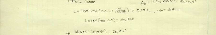
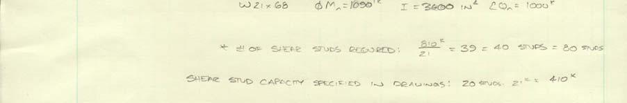
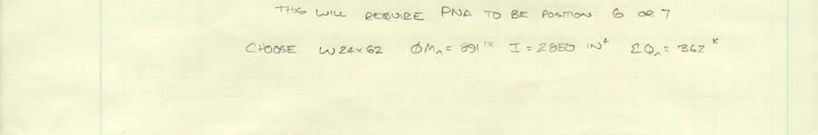
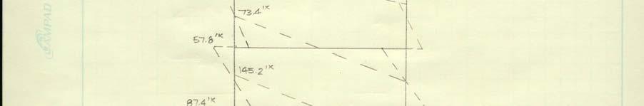
15 Structural Spot Checks: Column In the gravity load analysis for column sizes used for primary framing members of the Rutgers University Law School building East Addition, I generated much smaller members than those which were used. This is most likely because I applied gravity loads only and this is a moment resisting frame; I will perform another calculation in the lateral element analysis. Beam In my analysis of a typical composite beam acting as the second floor framing of the Rutgers University Law School building East Addition, I selected the a smaller beam than was chosen by the designer. In my analysis, I first assumed the Plastic Neutral Axis to be located in Position 1, at T = C, giving me a W24X55. I then used the equivalent force supplied by the shear studs used by the designer for which I generated a W24X62 beam when the beam chosen was a W24X68. This may have been a result of more stringent deflection criteria than I used in my design, or a slightly higher dead load from miscellaneous materials. Overall, the beam design which I was able to generate was only one size different from that chosen by the design professional. Lateral Force Resisting System The lateral resisting system for the primary East Addition was checked using the portal frame method to determine approximate moments and forces in the typical members. I chose to consider all frames as equal stiffness and distribute the lateral forces respectively. As a result, when the beam was analyzed, I came up with a W24X62 rather than the prescribed W24X68, only one size different than the designed beam. Also, when I used an approximate method to compare the column size chosen, I generated a W14X120, three sizes below the designed W14X159. There are several possibilities for which these results differ, one of which is that the approximate method of finding force from wind load moments may have undersized my column. Another reason for the discrepancy could be in the dead loads used to calculate the force or possibly from the live load reductions taken in the calculation, as it appears many reductions were not taken in the original design
16 Appendix: General Material Properties General Material Properties Concrete Structural Steel f 1 c,footings 4000 psi A992 F y 50 ksi Wide Flange Beams f 1 c,piers 4000 psi A-36 F y 36 ksi Channels, Angles, and Plates f 1 c,walls 4000 psi f y 60 ksi Reinforcing Steel f 1 c,typ. slab f 1 c,bridge slab 4000 psi 5000 psi Masonry Foundation System f 1 m 1500 psi q a 5000 psi Minimum Bearing Capacity 60 tons Minimum Pile Capacity Figure 2: Material Properties Summary Detailed Wind Load Calculations Wind Load: (Values Calculated from ASCE 7-05) V 90 mph Figure 6-1 Exposure Category B k d 0.85 Table 6-4 I 1.15 Table 6-1 k zt 1.00 Section z g 1200 Table 6-2 α 7.0 Table
17 North-South Gust Factor G f I z Q g r g q, g v 3.4 R z bar ft c 0.3 B ft L 94.2 ft h 82.2 ft L z l 320 ε n β 1.00 N Vz b bar 0.45 α bar 0.25 E 1.00 R n R h R B R L η Rh η Rb η RL East-West Gust Factor G f I z Q g r g q, g v 3.4 R z bar ft c 0.3 B 94.2 ft L ft h 82.2 ft L z l 320 ε n β 1.00 N Vz b bar 0.45 α bar 0.25 E 1.00 R n R h R B R L η Rh η Rb η RL North-South Direction L 94.2 ft B ft h 82.2 ft L/B Wall Pressures C p Windward 0.8 Leeward -0.5 Side -0.7 East-West Direction L 166 ft B 94.2 ft h 82.2 ft L/B Wall Pressures C p Windward 0.8 Leeward Side
18 North-South Wind Pressures Floor h (ft) Floor Height k z q z p Windward Leeward Penthouse Floor h above grade(ft) East-West Wind Pressures Floor Height (ft) p (psf) Windward Leeward Penthouse k z q z Overturning Moment: Level North-South Direction East-West Direction Height (ft) h total Width (ft) Area (sf) M o (ft*k) Width (ft) Area (sf) M o (ft*k) Roof Penthouse th Floor rd Floor nd Floor st Floor
19 Detailed Seismic Load Calculations Seismic Load: (Values Calculated from ASCE 7-05) S s 0.30 Figure 22-1 S MS S Figure 22-2 S M F a 1.6 Table S ds F v 2.4 Table S d Equation Equation Equation Equation Site Class: D Seismic Design Category: B Table Seismic Load: (Values Calculated from ASCE 7-05) Equivalent Lateral Force Procedure (As permitted by Table ) V 154 k C s W 6738 k Equation Equation R 3.5 I 1.25 T 1.51 T a 0.89 Table (4.0 used by engineer in original design) Table Section Equation C u 1.7 Table C t Table x 0.8 Table h n 75 ft
20 Building Weight: (As prescribed by ASCE 7-05 Section ) Level Wall Weight Floor Weight Total Weight Height (ft) h total Perimeter (ft) Area (sf) Weight (k) Area (sf) Weight (k) (k) Roof Penthouse th Floor rd Floor nd Floor st Floor Seismic Force Distribution: (As prescribed by ASCE 7-05 Section ) Level C vx F x (k) Mo (ft*k) Roof Penthouse th Floor rd Floor nd Floor st Floor


21 Column Spot Check Calculations


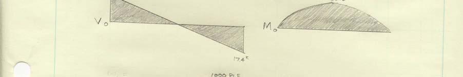


22 Beam Spot Check Calculations


23 - 22 -


24 - 23 -


25 Lateral-Resisting System Spot Check Calculations


26 - 25 -


27 - 26 -