CONSTRUCTION OF LOT 5 OF THE TURIN METRO LINE 2 TUNNEL SUMMARY
|
|
|
- Giles White
- 5 years ago
- Views:
Transcription
1 CONSTRUCTION OF LOT 5 OF THE TURIN METRO LINE 2 TUNNEL INJECTION OF FINES INTO THE CUTTERHEAD CHAMBER EXTENDS THE GROUND RANGE OF APPLICATION OF EPB TBMS SUMMARY The Lot 5 of the Turin Metro Line 2 includes the most challenging tunnel section to be executed in the entire project; this due to: o The Turin soil, mainly formed by boulders, cobbles and gravel, with minor sand and almost no fines is out of the application range both for standard EPB and Slurry TBMs o The ground water table is locally up to 15 m above the tunnel invert o There are of important and ancient buildings just above the tunnel as well many city services o There are curves with 180 m radius and the tunnel slope reach 5,6 % In consideration of the above problems and of the experience made in the excavation by EPB TBMs of the previous two lots (lots 3&4) of the same metro line, the Client the Designer and the Contractor decided to implement special measures with the aim to be able to execute the tunnel without causing any stability problem to the buildings and services above. These measures included: o The test and implementation of a specific soil conditioning o The test and implementation of a new technology for compensation of the fines that were missing in the in situ soil o The execution of special grouted soil structural bodies to protect the main buildings o The utilization of an EPB TBM specially modified to suit the soil characteristics and the tunnel horizontal and vertical alignment The combination of these measures allowed the successful execution of the tunnel in time and quality without causing any settlement and damage to the building and city services above the tunnel. In particular the introduction of the compensation of fines new technology have extended substantially the soil application range of EPB technique. CHAPTER 1 TURIN AUTOMATIC SUBWAY - LINE MAIN GENERAL CHARACTERISTICS The Turin Automatic Subway line 2 is composed by: o 7500 m of tunnels bored by n.3 EPB TBMs (from Fermi up to Porta Nuova stations) o 15 stations plus a deposit and workshop area for the Metro trains maintenance. o 18 shafts ventilation and safety purposes (14) as well for the execution grouting works (4). o A number of small tunnels to connect the main line to the shafts and to allow consolidation works constructed by conventional method. o 910 m of surface line connecting the train deposit to the first underground station of Fermi. 1

2 o 80 m of tunnel line excavated by traditional methods (from Principi d Acaja station toward XVIII December station) The civil works have been devised in n.6 lots, out of which Lots 3, 4 and 5 were the main ones and included the metro tunnel line and the stations. Since the beginning of 2004 the 5000 m of tunnel included in lots 3 and 4 were completed while today the EPB TBM that is excavating the 2500 m of tunnel included in lot5 have completed the most difficult section below important buildings between Pricipi di Acaia and Vinzaglio. The specialist Italian contractor SELI is in charge of the execution of the entire 7500 m tunnel line as partner and subcontractor of the Joint Ventures that awarded the different lots. While the excavation by the n.2 Lovat EPB TBMs of lots n.3 and n.4 has been already described in a previous report on the same magazine the present report deals with the execution by a modified NFM EPB TBM of the most challenging lot 5 tunnel section, which connect Principi di Acaia and Porta Nuova stations underpassing ancient buildings and monuments in one of the most crowded area of Turin. 1.2 LOT 5 ALIGNMENT AND GEOLOGY Tunnelling conditions for lot 5 were expected to be are widely different and more difficult in respect of the tunnel sections included in lots 3 and 4. The already critical characteristics of the Turin subsoil are combined in Lot 5 with additional difficulties as: o Presence of underground water up to a level of 15 m above the tunnel invert o Underpassing of important infrastructures, historical buildings and underground constructions. 2
3 o Presence of important traffic nodes along which vehicle circulation could not be interrupted. o Dense presence of city s main underground service lines and main sewerage ducts. o Presence of narrow curves with only 180 meters radius. o Presence of vertical gradients up to 5,6 % (first down-word and than up-word) and horizontal curves having a radius of 180 m combined with vertical curves Natural soil is basically composed of river s and glacial deposits: cobbles gravel and minor sand with variable grade of cementation passing from loose up to solid with presence of boulders and sandy lenses. Boulders might have dimensions ranging from 0,20-0,50 cm e 1,2 m and have methamorphyc origin with high grade of quartz contain. The tests and experiences made during the excavation of tunnels for lots 3 and 4 demonstrated that the absence of fine grained materials in the natural soil, was even more marked than predicted in the design stage ( less than 5% to be compared with 17 20% foreseen in the design studies). Lot s 5 alignment, in the initial section between Principi di Acaia and Vinzaglio stations, underpass several important buildings and other surface structures; for this reason its aligment presents two 180 m radius curves, an additional curve having 400 m radius and a slope up to +- 5,6 %. In this section the tunnel reach the deepest level and for this reason the ground water level is up to 15 m above the tunnel invert. For the execution of this section, after several studies, it was decided to deeply install on the NFM EPB TBM some innovative equipment and special technologies. CHAPTER 2 SPECIAL MEASURES TO BOOST EPB TBM TECHNOLOGY APPLICATION The experiences, monitoring and investigations activities performed during the execution of the tunnels for lots 3 and 4, were at the base of the studies and risks analysis made in preparation of lot s 5 tunnel construction. From the outcome of these studies both the Designer and the Contractor agreed that neither a traditional EPB TBM neither a Slurry Shield, as initially considered adequate, could have guarantee to excavate in the Turin fine-less ground and moreover in such difficult conditions (narrow curves under buildings and under water pressure) Due to the lack of fines the implementation of an effective EPB would have been impossible even through a massive utilization of foams and polymer conditioning. From the observation of the Turin ground grain size curves it appears evident that they are out of the range of application of standard EPB TBMs. 3
4 TURIN METRO LINE 1 Comparison between Turin soil curves and standard EPB application limit 100 EPB APPLICATION LIMIT passing (%) Turin ground soil curves ,1 0,01 grain size (mm) EPB limit according to Jancsecz et al. Compared to average Turin Lot 5 soil curve BOULD COBBELS GRAVEL SAND SILT CLAYS passing (%) ,1 0,01 0,001 0,0001 GRAIN SIZE (mm) media Lotto 5 limite EPB On the other side the utilization of an Hydro Shield would have encountered possible problems due to: o The very high permeability of the ground, locally greater than 10-3 o The large presence of cobbles and boulders 4
5 o The possible presence of voids and ancient services were the Slurry mud could be suddenly lost o The environmental and disposal problems created by the residual bentonite mud in the treated muck In consideration of the above the Designer and the Contractor agreed to utilise an EPB TBM modified and implemented by three major measures. Special soil conditioning i.e. to install on the TBM a conditioning system able to produce and inject in the excavation chamber foams reinforced with polymers. This to improve the quality and control of the foam utilised for the conditioning of the excavated muck in the cutterhead chamber Fines compensation i.e to inject in the excavation chamber of a fluid mix of fines and polymers. This to compensate the lack of fine materials in the in situ soil and allow the TBM to advance in an efficient EPB mode Structural grouting of soil bodies in critical area- i.e. to execute from surface and specific access tunnels cement grouting injections. This to form grouted structural soil bodies to secure the stability and avoid settlements in the area interested by important builidings Having implemented the above additional measures the design philosophy became: o To stabilize the tunnel face and control ground water inflows by operating the TBM in EPB mode (thanks to the special conditioning and fines compensation) o To stabilize the tunnel crown and avoid settlements by creating structural grouted soil bodies above the tunnel The EPB confinement operating pressure was calculated by Dr. Kovari (SELI consultant) taking into considerations a safety factor ranging from 1,5 to 2 depending from: the importance of the buildings above the tunnel, geotechnical characteristics of the excavated units, the shape/dimension of the grouted bodies. The values of the confinement pressure calculated at the front face resulted in a range varying between 0,2 0,5 bar at the tunnel crown. In the following sub-chapters are described in detail the special measures implemented. 2.a SPECIAL SOIL CONDITIONING One of the key factors for EPB mode excavation is a good conditioning of the soil. The addition of foams and/or other products contributes dramatically to reduce frictions, decrease the specific weight of the excavated material, increase volume filling inside the chamber, reduce eventual filtration and in general to form the optimum EPB paste optimising therefore the both the face stabilization and the TBM penetration rate. What is important for a successful application is anyhow to select the best possible foam/additive for each specific application and to correctly set up the foam plant on the TBM in order to reach a good quality foam and obtain the desired FER and FIR. After an accurate laboratory and market investigation, taking also into consideration the environmental restrictions, it was decided to adopt a foam obtained by mixing compressed air and water with the foaming agent Foamex by Lamberti, stabilised by the polymer agent Drillam MV. This mixture was able to form a dense and long term stable foam that did migrate even through the very permeable soils of Turin. Stability and strength of the foam bubbles could be eventually increased by adding a percentage of Drillam MV. 5
6 Stability and density of foam are controlled by varying: o the concentration of foaming agent between (between 1% and 5%) in the water mix o and o the F.E.R., Foam expansion ratio, (between 5 and 15) which represent the increase of volume of the foam formed by mixing compressed air with the water/foaming agent mix Another important parameter to take into consideration in soil conditioning in EPB operation is represented by F.I.R (foam injection ratio) which represent the volume of injected foam per cubic meter of excavated soil. Approximately, F.I.R. can vary from: 20%, for clay coesive soils 30% for sandy silty soils. > 40% for gravel and sandy soils In lot 5 tunnels the mean values utilised in soil conditioning have been: o Concentration of foaming agent: 1,5 % o F.E.R : 8 o F.I.R 46% Table below shows the FIR real values utilised in the most critical section of tunnel excavated in Lot 5. Actual FIR values during excavation of the tunnel section bewteen the stations of Piazza XVIII Dicembre - Principi d'acaja FIR (%) Precast lining rings Another important aspect to be considered when operating an EPB TBM is the quality and capacity of the foaming plant installed on the machine. Due to the difficult ground to be conditioned, for the NFM TBM utilised in Lot 5 it was decided to substitute the original plant installed on the TBM by a new plant supplied by SPOILMASTER (England) specifically designed for the application. The main features of this plant are: o The capacity of mixing foam and polymer to form a thicker and more stable foam o The automatic control of all conditioning parameters through several PLC s while the TBM operator can check all its working data. o The automatic adjustment of the quantity of foams injected according to the TBM penetration and the EPB working pressures 6
 through proper nozzles which position was accurately studied to give a correct and")
7 Inverters adjust speed for the pumps to add the three component (polymer, foaming agent and water). The foam is injected at approx 4 5 bars (inside the screw conveyor, at the cutterhead, in the working chamber) through proper nozzles which position was accurately studied to give a correct and homogeneous distribution. Figura 4 Foam generators 2.b Structural grouting of soil bodies In order to secure the stability of the buildings located above the tunnel route it was decided to study, design and implement a special grouting scheme. Grouting design had to be extremely accurate since it had to take into consideration various aspects such as: The presence of underground lines not to be hit by drillings works The presence of buildings, structures, underground constructions that were limiting the drilling possibility. To limit the disturbance caused by the drilling and grouting operations on surface in The presence and level of the underground water table Four different shapes of injected body were finally designed. All these shapes were designed to form a tri-dimensional structural bodies to avoid that any overexcavation and/or instability occurred at tunnel level could be transmitted to the surface buildings. A certain number of full face injected body, associated with injection of special mixture to lower the soil permeability, were also executed to allow major cutterhead planned maintenances. 7
8 The execution of drillings for the grouting works in many cases was done utilising mini crawled drillers placed inside small tunnels (section approx. 9 sqm) and located between the surface and the subway level. Those tunnels were bored in traditional method through access shafts and/or through the same shafts foreseen for the permanent works for ventilation and safety purposes. During grouting execution all injection parameters were recorded to increase the knowledge and behaviour of soil and to detect the local presence of fine lenses in case of low absorption of injected fluids. Quality of injected mixture was controlled during operations both in terms of density and of compressive strength, in order to compare the designed values (γ = 1.25 t/m3 and σ f = 10,0 12,0 t/m 2 ). 8


9 9

10 2.c Compensation of fines SELI performed a test program in its laboratory to study the soil conditioning problems of the Turin soil. From the result of these tests it was clear that the injection of a combination of foam and polymers was not enough to produce a plastic no segregating muck. As a consequence it was decided to study the alternative to complement the foam and polymers conditioning with the injection of a fluid mix containing rock powders. In order to produce a stable mix, the following main aspects were considered: A filler having a fineness modulus and size for closing of the curve of the natural alluvial material. A polymer able to stabilize the mix and satisfy the environmental aspects at the disposal area A viscosity of the mix suitable to be pumped through the small conduits of the cutterhead rotary joints Filler characteristics Many fillers were tested such as coal, rise, fly ash, perlite, bentonite, fine sand 0 2 mm but all of them have been rejected for the impact on environment, economic and availability aspects. After several tests limestone rock flour was chosen. Two different fillers grain size were mixed in order to adjust the original alluvial percentage distribution: 50% of 40 µ size named VNT 50% of 20 µ size named M20 The blend was chosen according to the average of several sieve analysis performed on in situ soil samples taken under the water table in order to fill the grain size gap. Polymer The polymer has a double effect: stabilize the slurry mix avoiding the components segregation and the consequently bleeding penetrate through the soil at the tunnel face for few centimetre helping in the face support and in ground water control However the polymer alone can not replace the lack of fines in the ground since the polymer does increase the viscosity of the mix but not the mix specific gravity, which remain 1 Kg/l if no fines are added. SELI tested many polymers available from the market having different chemical composition and all environmentally acceptable 10


11 After having selected the most suitable polymer for the application additional tests were performed to individuate the best dosage to improve the hauling time and the mixing condition. Different dosages have been tested taking in account: filler grain size filler/water ratio hauling time mixer type : sand with polymer sand without polymer injected mix of fines and polymer 11
12 Mix Slump in order to measure the plasticity/workability of the treated muck slump cone tests were performed until the target mm value was reached. The slump tests provide a simple workability index for the conditioned muck. Viscosity The mixes viscosity have been determined according to the Brookfield RV 20 rpm method The viscosity of the mix tested vary according to: filler/water ratio filler grain size polymer chemical composition and structure polymer dosage The measured viscosity of the mixes tested vary between 545 cp and cp The correct choice of the filler grading, polymer and filler/water ratio should take into consideration proper pumping of the mix from TBM back to the front face through to the rotary coupling and inside the working chamber, whenever necessary, without clogging. Preparing the mix The mix was prepared outside in a special plant designed by Seli. The plant was equipped with one high capacity mixer, balances for filler, water and polymer and two silos for the two fillers; all the mix preparation phases were controlled by a PLC system. Transporting and injecting the mix The slurry mix was pumped down inside a transport mixer that was part of the mucking train. Once reached the TBM back up the mixer was connected to a pump that directly injected the mix at the face through the cutterhead rotary joint. A custom made PLC program controlled by the TBM operator supervises and monitors the injection of fines process. The plastic, well-graded muck obtained by combining the special soil conditioning with the fine injection compensation allowed to achieve: more uniform pressures in the excavation chamber better control of groundwater inflow by reducing the permeability high compressibility reduced friction and heat build up in working chamber CHAPTER 3 MONITORING SYSTEM The monitoring system was designed to record in real time: 1. the stresses, strains and displacements of the tunnel under construction 2. the settlements of the soil at surface and below the surface. 3. the displacements and rotations of existing buildings Due to the importance this tunnel and its potential interference with the urban net, the monitoring points and the relevant instrumentation have been widely redundand. 1. Monitoring of the tunnel under construction These measurements were taken by installing precasted rings equipped of embedded instruments such us: strain gages, pressure cells both along radial and longitudinal direction and four (4) 3d targets for convergence measurements. 12
13 Monitoring sections for lining placed along the tunnel are correlated to other measurements taken for the soil settlements and the external buildings. 2. Settlements of the soil at grade and below the surface. Checking of superficial settlements produced by the TBM excavating action was conducted by reading of topographic level benchmarks placed both along axial and transversal directions. Deep settlements were measured by multi-base extensometers and increx systems installed at various position in order to read eventual displacements at different deepness. Surface topographic monitoring Transversal section of the settlements at street level as a function of the distance from the tunnel axle at different distances of TBM cutterhead 0,0010 0,0005 Settlements (m) 0, ,00-20,00-15,00-10,00-5,00 0,00 5,00 10,00 15,00 20,00 25,00-0,0005-0,0010-0,0015-0,0020 Distance CPL from tunnel axle (m) Transversal sections of surface settlement monitorino readings - Surface settlements along the tunnel axle as a function of TBM excavation face location 0,0005 0,0000 SIN-2 SIN-1 SC-5 SC-4 SC-3 SC-2 SC-1 A2 1-SP B1 A1-0,0005-0,0010 Settlements [m] -0,0015-0,0020-0,0025-0,0030-0,0035-0, , , , , , ,00 Chainage [m] Longitudinal profile of surface settlement at different TBM face positions 13
14 3. Displacements and rotations of existing constructions Monitoring of existing buildings was performed by taking into consideration a general scale of risk for each of them. This evaluation, prepared on the base of the age of the building, its historic importance, the distance from the tunnel, its destination, gave a final rate of risk according to which a certain number of instruments were placed and a consequent frequency of readings was taken. The placed instruments consisted on: level benchmarks micro deformation meters micro crack meters triaxial vibro-meters All the instrumentation complied with rules indicated by UNI 9916 and DIN UPPER LIMITS VALUES FOR MONITORING DATA The real time readings of the monitoring instrumentation, gave the opportunity to detect at any moment eventual displacements values that were reaching the upper admissible limits. Two (2) different limits were set: Attention limit: defined as a portion of the calculated deformation (30%). Its reaching determines a more frequent monitoring reading and much more controlled excavation process. Alarm limit: defined as a greater portion of calculated deformation (60%). Its reaching could bring to uncontrollable risky situation of collapses and caving. Excavation is immediately suspended and risk committee is timely informed to decide remedy measures. 3.2 RESULTS AND DATA INTERPRETATION All the data were recorded, elaborated by PCs and read by a team of engineers. The lower attention limit was never reached and all movements and displacements were very minimal. CHAPTER 4 TBM CHARACTERISTICS AND PERFORMANCES 4.1 MAIN CHARACTERISTICS OF THE TBM The excavation of the lot 5 tunnel section was performed by using an EPB TBM NFM model This machine was used before in other two projects. SELI however performed several improvement and modifications before to deliver the TBM to the Turin sit, and basically. New cutterhead configuration. N.2 special Copy cutters installed on the cutterhead New extended stroke shields articulation system to cope with the 180 m curve New Hyperbaric chamber New twin weighting system of extracted muck.. New configuration for the cutterhead. The cuttehead was designed to penetrate through alluvium deposits with different grade of cementation. It is equipped with: scrapers rippers 14
15 cutters The different cutting tools can be interchanged and replaced from any point inside or outside the working chamber. Copy cutter This system allowed to cope with the narrow curves foreseen for the tunnel of lot 5. It is composed of 2 external five blades cutters installed in symmetric position on the cutterhead. Each copycutter extends up to 140 mm out of the standard cutting profile. During the cutterhead rotation the two cutters are extended and retracted actuated by hydraulic cylinders and controlled by PLCs. The elliptical shape of the excavated profile allows the excavation of the TBM in narrow curves and minimize the over excavations. The system proved to work very efficiently Articulation system The Articulation system of the TBM was changed to allow openings of the shield joint up to 200 mm, improving therefore the capability of the TBM to follow tunnel alignment along short radius curves. Hyperbaric chamber Hyperbaric chamber was installed to allow the access to the cutterhead chamber under compressed air for maintenance and inspections. This chamber has a double compartment. Weighting system and control of extracted muck.. Control of the weight of the extracted muck is a fundamental aspect in EPB excavation. This measurement allows to evaluate the correspondence between the weight of the extracted soil and the theoretical weight related to the TBM advance. Important differences between the two weights indicate the presence of over excavations or variations in the level of muck in the cutterhead chamber. On the NFM TBM used in lot 5 two weighting scales were installed on the back-up conveyor and the recorded values were displayed on the monitor installed inside the operator cabin and compared with the theoretical weight. 4.2 TBM ACTUAL PERFORMANCES The arrival on site of the TBM components was completed on November 15th 2003 and in about two months 1 the assembling and testing was completed. First boring was done on January 25 th Arrival at the first station called XVIII Dicembre was achieved on April 5th 2004 with a general advance rate of 8.15 meters per day. During the TBM translation inside the station, special maintenance was performed to the cutterhead and the screw conveyor. 1 Not considering season holidays for Christmas 15
16 The following tables summarize the TBM performances and cutting tools wear data in this first tunnel stretch: lenght (m) aily advance Mean Mean OP average onfin EPB ean FIR (m/gg) ust (ton) torque (mm/min) pressure (%) (ton*m) (bar) utting tools replaced Cutters Rippers Scrapers py Cutter Total: The excavation of the second section was resumed on April 22nd and completed on June 17th The average advance rate for the whole second stretch resulted m/day with a peak value of 18 m/ day. The following tables summarize the TBM performances and cutting tools wear data in this second tunnel stretch between XVIII Dicembre station and Principi di Acaia Shaft. lenght (m) Daily advance (m/gg) Mean trust (ton) Mean torque (ton*m) ROP average (mm/min) Confin EPB pressure Mean FIR (%) (bar) Cutting tools replaced Cutters Rippers Scrapers Copy Cutter Total : The graph below visualize the TBM production during the excavation period. TBM ADVANCE CHART ,8 m/d Jan 26th- 04 April 5-04 XVIII DIC March ,2 m/d April 22nd 04 June 17th-04 1/1 16/1 31/1 15/2 1/3 16/3 31/3 15/4 30/4 15/5 30/5 14/6 29/6 16

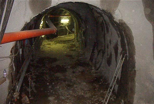
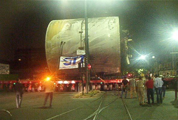
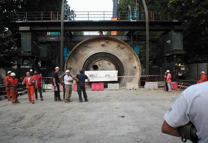
17 4.2 COMMENTS ON TBM PERFORMANCES The structural grouting of soil bodies secured the stabilities of the critical buildings avoiding settlements. The twin copy cutter worked very efficiently and the 180 m curves were driven by the TBM with very accurate steering. The compensation of fines proved to be essential to form a suitable EPB paste and to control the ground water, avoiding free inflows through the screw conveyor. The combination of special soil conditioning and compensation of fines allowed an efficient EPB operation of the TBM. No face instabilities and over-excavations were observed This success was so evident and important that for the future sections to be excavated of the Turin metro line the amount of structural grouting has been drastically reduced by the designer. CHAPTER 5 TBM SPECIAL LIFTING AND TRANSFER SYSTEM The urgency of completing the works for the winter Olympic games pushed the decision to speed up the TBM removal from the shaft and transfer the same TBM to the next starting station. SELI studied a special lifting of the TBM in a single piece (except cutterhead). The TBM was lifted by hydraulic hoist equipped with 4 hydraulic jack having a capacity of 180 ton each and carried on special multiple wheels modular car. The TBM transfer was anticipated by a careful study of all interferences, aerial lines, traffic, underground services, structures and load capacity of bridges. 17
18 18

19 Conclusions Lot 5 of the Turin metro line 1 gave the opportunity to experiment new technologies in the EPB tunnelling field. The compensation of fines technique allows to extend the application of EPB technique well behind the standard limits. The costs of developing and applying this new technique will return to the Client in term of savings in the execution of the future extensions of the metro line were consolidation works could be minmized 19