Consulting Engineers and Scientists. Closure Plan. Submitted by: GEI Consultants, Inc Voyager Drive Green Bay, Wisconsin
|
|
|
- Letitia Peters
- 5 years ago
- Views:
Transcription


1 Consulting Engineers and Scientists Regulation Compliance Report Submitted to: We Energies 333 West Everett Street, A231 Milwaukee, Wisconsin Submitted by: GEI Consultants, Inc Voyager Drive Green Bay, Wisconsin Project John M. Trast, P.E. Senior Consultant Paul M. Garvey, P.G. Senior Consultant
2 Regulation Compliance Report Table of Contents 1. Introduction 1 2. Closure Narrative 2 3. Final Cover System Compacted Barrier Layer Geomembrane Drainage/Rooting Layer and Topsoil 5 4. Schedule for Closure 6 5. Conclusion and Certification 7 Appendix A Drawings PM-8 Phasing - Cell 1 Base Grades, Pleasant Prairie Power Plant Ash Landfill, We Energies, Plan of Operation Modification, Village of dated April 4, 2012 PM-10 Phasing - Cell 1-2 Waste Grades & Cell 3 Base Grades, Pleasant Prairie Power Plant Ash Landfill, We Energies, Plan of Operation Modification, Village of Pleasant Prairie, Wisconsin dated April 4, 2012 PM-16 Final Cover Grades, Pleasant Prairie Power Plant Ash Landfill, We Energies, Plan of Operation Modification, Village of dated April 4, 2012 PM-17 Final Cover Grades, Pleasant Prairie Power Plant Ash Landfill, We Energies, Plan of Operation Modification, Village of dated April 4, 2012 PM-18 Cross-Sections, Pleasant Prairie Power Plant Ash Landfill, We Energies, Plan of Operation Modification, Village of dated April 4, PM-20 Construction Details, Pleasant Prairie Power Plant Ash Landfill, We Energies, Plan of Operation Modification, Village of dated April 4, 2012 JXT:cah K:\WEC Energy Group\ _We Energies PPPP LF Engineering Assistance\In_Progress\Reports\CCR \R PPPP CCR _October 2016.docx GEI Consultants, Inc. ii
3 Regulation Compliance Report 1. Introduction We Energies owns and operates a solid waste disposal facility adjacent to the Pleasant Prairie Power Plant (PPPP) in Section 9, Township 1 North, Range 22 East, in the village of Pleasant Prairie, Kenosha County, Wisconsin. The landfill property is bounded on the north by State Highway 50 (75th Street), on the south by Bain Station Road, and on the east and west by active rail lines. The We Energies PPPP Ash Landfill is regulated as an industrial waste landfill by the Wisconsin Department of Natural Resources (WDNR) under the provisions of Chapter 289 Wisconsin State Statues, and all applicable requirements of Chapters NR 500 of the Wisconsin Administrative Code. The design, construction, operation, closure, and post-closure care requirements are specified in the WDNR conditionally approved Plan of Operations, License No. 2786, FID# The construction of Cell 1 was completed and the landfill was placed into operation in In addition to the state regulations, the landfill is also required to comply with 40 CFR Part 257 Subpart D Standards for Disposal of Coal Combustion Residuals in Landfills and Surface Impoundments and is defined as a CCR unit and existing CCR landfill in accordance with Future landfill cells are permitted by the WDNR in the conditionally approved Plan of Operation and defined as lateral expansions under when constructed. This report fulfills the requirements for a written of the PPPP Ash Landfill, Cell 1 in accordance with Criteria for Conducting the Closure or Retrofit of CCR Units. In accordance with (b)(1) this report describes the engineering design of the landfill, phased development, a description of the final cover system and how the final cover will be constructed, and how the final cover system will meet the applicable performance standards contained in (d). In addition, it also includes an estimate of the maximum inventory of CCR, an estimate of the maximum open area that would require closure at one time, and a generalized schedule based on the anticipated landfill filling rates and disposal volumes. This closure plan includes the following sections: Section 1 Introduction Section 2 Closure Narrative Section 3 Final Cover System Section 4 Schedule for Closure Section 5 Conclusion and Certification GEI Consultants, Inc. 1
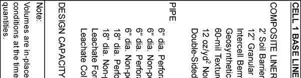
4 Regulation Compliance Report 2. Closure Narrative This section provides the closure narrative as required by (b)(i). Closure of Cell 1 will be accomplished by leaving the CCR in place and installing a final cover meeting the requirements of (d)(3) over the CCR. The final cover system is described in Section 3. The areal limits of Cell 1 are shown on drawing PM-8 in Appendix A. Closure activities for Cell 1 will commence when CCR disposed in the cell reach final waste grades shown on drawing PM-10 in Appendix A. It will be necessary to laterally expand the landfill with the construction of Cell 2 before final waste grades are completed in Cell 1. At that time this closure plan will be updated to comply with the federal rules (b)(1)(iv) requires an estimate of the maximum inventory of CCR ever on the site over the active life of the CCR unit. The design capacity of Cell 1 is 199,200 cubic yards. Therefore, prior to lateral expansion of the PPPP Ash Landfill, in accordance with the approved Plan of Operation, the maximum CCR inventory of the landfill is 199,200 cubic yards (b)(1)(v) requires an estimate of the largest area of the CCR unit ever requiring final cover, at any time during the active life of the CCR unit. The area of Cell 1 is 8.1 acres. Therefore, prior to lateral expansion of the PPPP Ash Landfill, in accordance with the approved Plan of Operation, the largest area of the CCR unit (Cell 1) requiring a final cover during the CCR unit s active life is 8.1 acres (d)(1)(i). The final cover system described in Section 3 is a composite final cover system which will envelop the CCR, minimizing post-closure infiltration and the potential release of CCR, leachate, or contaminated run-off from the closed unit. Fugitive dust from exposed CCR before and during final cover construction will be managed in accordance with the Fugitive Dust Control Plan. Surface water that has come into contact with CCR before and during final cover construction will be managed as leachate in accordance with the Runon and Run-off Control Plan (d)(1)(iii). Slope stability of the CCR and final cover is enhanced in the manner in which the CCR is conditioned, placed, and compacted; how the facility is operated to promote storm and contact water management; and how the leachate collection system is designed and monitored to ensure leachate is being removed from the waste and not allowed to build-up within the landfill. The permitted final cover slopes will be at a 5% minimum slope at the top of the landfill to promote surface water drainage and prevent ponding due to the settlement of the final cover system. The perimeter side slopes of the landfill will be at a maximum slope of 25% to provide long-term stable slopes that promote stormwater drainage, can be protected from excessive erosion, and safely maintained (d)(1)(iv). The final cover system described in Section 3 will minimize infiltration, which in turn minimizes the demand on the leachate collection system. The final cover will be vegetated with grass to promote evapotranspiration and prevent erosion. The final cover system vegetation will be maintained by fertilizing as necessary to develop a well-established GEI Consultants, Inc. 2
5 Regulation Compliance Report vegetative cover and periodic mowing to stimulate root growth and prevent the establishment of woody vegetation. Final slopes will be between 5% and 25% to facilitate mowing. Slopes greater than 10% will be covered with erosion matting after seeding to minimize erosion during the establishment of vegetative cover (d)(1)(v). The final cover system described in Section 3 uses readily available equipment and materials and can easily be completed in a single construction season. GEI Consultants, Inc. 3
6 Regulation Compliance Report 3. Final Cover System This section is included to fulfill the requirements of (b)(1)(iii). Filling to final contours will result in a final slope no greater than 25% sloping downward from the center of the fill area to the perimeter of the site. The top portion of the landfill will be graded to no less than 5% sloping downward from the center to ensure positive drainage to the perimeter of the site. Drainage features, such as the perimeter ditches, terraces, and runoff channels will be constructed, as necessary, to accommodate surface runoff from phased closure. The final cover system has been designed to minimize leachate generation by limiting percolation through the final cover barrier layer, promoting subsurface drainage to limit head on the barrier layer, and establishing vigorous plant growth to maximize evapotranspiration. The final cover system has also been designed for stability and to reduce maintenance. Specifically, the final cover system includes a composite barrier layer system consisting of 2 feet of soil or compacted FGD filter cake/fly ash and a polyethylene geomembrane. The remainder of the cover system consists of a geocomposite drainage layer, 24 inches of rooting zone material, and 6 inches of topsoil. The geocomposite drainage layer is incorporated into the final cover system cross-section to promote subsurface drainage and prevent the build-up of head pressure on the barrier layer and pore pressures in the final cover system soils. The hydraulic conductivity of the final cover system is required by (d)(3)(i)(A) to be less than or equal to the hydraulic conductivity of the bottom liner system or natural subsoils present or a hydraulic conductivity no greater than 1.0E-05 cm/s, whichever is less. The PPPP Ash Landfill is designed and constructed with a composite base liner system consisting of 2 feet of compacted soil, geosynthetic clay liner, and polyethylene geomembrane. The approved final cover system is a composite final cover consisting of a 2-foot compacted barrier layer, polyethylene geomembrane, drainage layer, and vegetated soil layers. The final cover system meets the requirements of (d)(3)(i)(A). Construction equipment and methods normally used in developing landfills and performing earth-moving projects will be used. The following sub-sections discuss the construction of the individual components of the final cover system. Layout and details of the final cover system are shown on the drawings included in Appendix A. 3.1 Compacted Barrier Layer A minimum 2-foot-thick layer of compacted barrier layer constructed of soil or FGD filter cake and fly ash will be used as the soil component of the composite barrier layer. The materials will be placed and compacted with a large vibratory smooth-drum roller, with a minimum operating weight of 15,000 pounds, and while in vibratory mode, can provide 30,000 pounds of compactive energy. The barrier layer will be placed and compacted in lifts not exceeding 6 inches. The prepared barrier layer shall provide a firm, smooth surface for GEI Consultants, Inc. 4
7 Regulation Compliance Report deployment of the geomembrane. The barrier layer should be free of any angular particles protruding from the surface greater than 0.5 inches, sharp breaks in grade or excessive rutting greater than 0.2 feet. The completed barrier layer will have a maximum hydraulic conductivity of 5x10⁻⁵ cm/s. Based on the laboratory test results of the FGD filter cake and typical fly ash properties, the compaction and hydraulic conductivity specifications should be achievable using standard construction equipment and methods normally used in developing landfills and performing earth-moving projects. 3.2 Geomembrane The geomembrane component of the final cover system will be a 40-mil textured linear lowdensity polyethylene (LLDPE) geomembrane. The LLDPE geomembrane has been selected in order to provide flexibility of the final cover system to accommodate expected settling and subsidence in accordance with (d)(3)(i)(D). Geomembrane panels will be positioned by suspending rolls of material with a front-end loader and unrolling the suspended material by hand or with the aid of an ATV, as the loader remains stationary. The geomembrane will be installed in a loose and relaxed condition. Panels will be overlapped approximately 4 inches and fusion-welded together. At seam intersections and other repair locations, a geomembrane patch extending a minimum of 12 inches beyond the intersection or repair will be extrusion-welded into place. All seams will be non-destructively tested by air or vacuum testing. The integrity of fusion welds will be air tested, and extrusion welds will be vacuum-tested. 3.3 Drainage/Rooting Layer and Topsoil A geocomposite drainage layer and a 24-inch-thick rooting zone layer meeting the requirements of (d)(3)(i)(B) will be installed above the geomembrane final cover. The drainage layer will be installed to aid in the removal of subsurface storm water drainage; the rooting zone layer will be installed to support vegetative growth and both layers will provide protection of the geomembrane and compacted barrier layer. The geocomposite will be deployed such that the seams run perpendicular to the contour lines of the slope to the extent possible. The geonet will be cable-tied every 3 feet along the edge of the panels and every 12 feet for end seams. The top geotextile will be sewn. The rooting layer will be placed over the geocomposite in a single lift using low ground pressure dozers. The material will be classified as SW, SP, SM, SC, ML, or CL and have a maximum particle size of 3 inches. The rooting layer will consist of on-site or off-site soils. Meeting the requirements of (d)(3)(i)(C), topsoil capable of sustaining vegetative growth will be placed and spread into a uniform loose lift thickness of 6 inches. Once placed, the topsoil will be fertilized, seeded, and mulched. On all slopes greater than 10%, a temporary straw mulch blanket will be used to limit erosion and protect the seed prior to the establishment of vegetation. GEI Consultants, Inc. 5
8 Regulation Compliance Report 4. Schedule for Closure This section is included to fulfill (b)(1)(v). The first phase of construction, Cell 1 was placed into service in In accordance with the WDNR approved Plan of Operation, the landfill has a phased development plan, describing the construction, operation, and closure of each phase of the landfill from the construction of Cell 1 to the closure of Cell 6B. In general, the development plan requires active landfill cells which have reached final waste grades be closed as soon as practical to limit the maximum open area, leachate generation, and the potential operational problems. In order to reach the design CCR grades in Cell 1 on the north, east, and west slopes, Cell 2 will be constructed. A schedule for completing all activities necessary to satisfy the closure criteria is dependent on the CCR generation rates, beneficial reuse programs, and disposal rate volumes. However, final closure of Cell 1 will begin no later than 30 days following the final waste receipt for the CCR unit in accordance with (e)(1). Final cover construction at the PPPP Landfill will be completed in accordance with the WDNR approved Plan of Operation under License No Therefore no additional state or local approvals are required for We Energies to begin construction of the next phase of the landfill or closure of an existing phase. The final cover system described in Section 3 uses standard and readily available equipment and materials and can easily be completed in a single construction season. GEI Consultants, Inc. 6


9
10 Regulation Compliance Report Appendix A Pleasant Prairie Power Plant Ash Landfill, We Energies, Final Cover Design Drawings PM-8 PM-10 PM-16 PM-17 PM-18 PM-20 Phasing - Cell 1 Base Grades Phasing - Cell 1-2 Waste Grades & Cell 3 Base Grades Final Cover Grades Final Cover Grades Cross-Sections Construction Details GEI Consultants, Inc.
11
12
13

14
15
16