Executive Summary...2 Introduction...3 Structural System Overview Buffalo,...4 Foundation...4 Floor System...4 Gravity System...4 Lateral System...
|
|
|
- Noel Armstrong
- 5 years ago
- Views:
Transcription

1 Table of Contents University at Buffalo CTRC/Incubator Executive Summary...2 Introduction...3 Structural System Overview Buffalo,...4 New York Foundation...4 Floor System...4 Gravity System...4 Lateral System...5 Codes and References...8 Original Design Codes...8 Thesis Design Codes...8 Materials...9 Building Loads...10 Design Floor Dead Loads...10 Floor Live Loads...11 Wind Loads...12 Seismic Loads...14 Snow Loads...15 Computer Model...16 Lateral System Analysis...17 Relative Stiffness of Lateral Elements...17 Center of Rigidity...18 Center of Mass and Center of Pressure...19 Load Combinations...20 Drift Analysis...21 Overturning and Impact on Foundations...22 Lateral Member Spot Checks...26 Conclusion...27 Appendix...28 Appendix A: Typical Floor Plans and Elevations...29 William McDevitt November 29, 2010
2 Table of Contents Executive Summary...2 Introduction...3 Structural System Overview...4 Foundation...4 Floor System...4 Gravity System...4 Lateral System...5 Codes and References...8 Original Design Codes...8 Thesis Design Codes...8 Materials...9 Building Loads...10 Design Floor Dead Loads...10 Floor Live Loads...11 Wind Loads...12 Seismic Loads...14 Snow Loads...15 Computer Model...16 Lateral System Analysis...17 Relative Stiffness of Lateral Elements...17 Center of Rigidity...18 Center of Mass and Center of Pressure...19 Load Combinations...20 Drift Analysis...21 Overturning and Impact on Foundation...24 Lateral Member Spot Checks...26 Conclusion...27 Appendix...28 Appendix A: Typical Floor Plans and Elevations...29 Appendix B: Wind Analysis...32 Appendix C: Seismic Analysis...38 Appendix D: Snow Loading...41 Appendix E: Lateral Load Distribution...42 Appendix F: Lateral Member Spot Checks
3 Executive Summary The following document is the third technical report of senior thesis and includes information regarding the structural lateral system of the Kaleida Health and University at Buffalo, Global Heart and Vascular Institute. This project will be referred to throughout this report simply as GHVI. This report includes a structural system overview, a summary of building loads, and an in-depth lateral system analysis. GHVI is a ten story medical facility in the city of Buffalo, NY. The building is square in shape with a length and width of 221 feet, and a height of 185 feet. The foundation is made of grade beams and steel helical piles that are driven 82 to 87 feet deep. Floor construction entails composite metal deck resting on steel superstructure. A standard bay size of 31-6 by 31-6 is used throughout the building, utilizing W14 columns of varying weight to make up the gravity system. The lateral system is comprised of braced frames which are located near the perimeter of the building. In order to analyze the lateral system of GHVI a three dimensional computer model was created using ETABS. The steel columns and braces of each frame were modeled and assigned material and frame section properties. Columns were pinned at the base and beams and braces were released to prevent them from taking out-of-plane bending. A rigid diaphragm was drawn with additional area masses to model each floor level. The ETABS model was used to determine the relative stiffness of each frame. A 100 kip load was applied to the top of each individual frame, and the lateral displacement was measured. From these values the stiffness and relative stiffness of the frames was calculated. With the relative stiffness it was then possible to distribute the lateral load to the building. After confirming the location of the centers of rigidity, mass, and pressure, it was determined that both direct and torsional shear must be considered for this building. Seven basic load combinations were taken from ASCE 7-10 and input into the ETABS model to determine the controlling load case for this building. Although unexpected, seismic loading was shown to control in both the North-South and East-West directions. With this controlling load combination determined, it was then possible to examine drift, consider overturning moment and foundation impact, and perform spot checks of different lateral members. In the end all story and total drifts were found to be acceptable, the foundation is sufficient, and the inspected lateral members were adequate
4 Introduction GHVI is a state-of-the-art medical facility and a fundamental component in a joint undertaking between Kaleida Health Systems and the University at Buffalo School of Medicine. The building spans ten levels and includes exam rooms, classrooms, offices, a café, a wellness center and library, and a research facility. It is intended to bring patients, surgeons, and researchers together to collaborate in an unprecedented way. Key themes considered throughout the design were collaboration, flexibility, and comfort. Kaleida Health Systems sought a structure that would link clinical and research work and combine all vascular disciplines. A spirit of collaboration was the driving force behind bringing both Kaleida and the University at Buffalo together in a single structure. Keeping this in mind, the design team developed the facility with a collaborative core which enables interaction among those working within the facility. This collaborative learning environment brings together research, ideas, and solutions and results in better patient care. A universal grid design increases the flexibility of space and achieves measurable advantage in initial capital cost, speed to market, operating economy, and future adaptability. The universal grid is comprised of three 10-6 building modules and forms a 31-6 x 31-6 structural grid capable of integrating the building s diverse functions. When combined with an 18 floor-to-floor height, the flexible grid creates an open plan capable of adapting to present and future healthcare needs. The building will be able to incorporate unknown, but rapidly changing technological developments within the industry, also giving it longevity through its adaptability. With comfort in mind, a separate hotel level was designed on the second floor and separated from the procedural floors. Functionally, the hotel is comprised of private patient rooms and a small lounge area. Other family lounges are also provided and the perimeter of the building is shaped to bring in as much natural daylight as possible. The vision of GHVI is to create an atmosphere that is more than a simple hospital, but instead a facility for world-class treatment and state-of-the-art technology
5 Structural System Overview Foundation Based on the recommendations of the October 2008 Geotechnical Report by Empire Geo-Services, Inc., the foundation of GHVI consists of grade beams and pile caps placed on top of steel helical piles. The helical piles are HP12x74 sections with an allowable axial capacity of 342 kips (171 tons) which are driven to absolute refusal on limestone bedrock 82 to 87 feet below the sub-basement finish level. Grade beams and pile caps have a concrete strength of 4000 psi, and it should be noted that the width of the grade beams equals that of the pile caps at the foundations of the braced frames. The grade beams provide resistance to lateral column base movement, and the pile caps link the steel helical piles and the structural steel columns of the superstructure. Spanning the grade beams is the sub-basement floor, a 5 slab-on-grade. Due to the slope of the site, part of this sub-basement is below grade, and therefore a one foot thick foundation wall slopes along the west elevation of the sub-basement. Floor System The floors of GHVI consist of 3 composite metal deck with a total slab thickness ranging from 4 to 7½. The metal deck is 18-gage galvanized steel sheets resting on various different beam and girder sizes. These sizes change throughout the structure because of the various functions of the spaces. The bay sizes through the building are mostly 31-6 by 31-6, with beams spaced at As was discussed in the introduction, this universal grid design increases the future flexibility of the space. A slight variation in the floor can be seen on Levels 6-8. On these levels, part of the floor structure is left open to provide for the collaborative atrium that was designed to bring the various disciplines together. Gravity System Steel columns are used throughout the building to transmit the gravity load to the foundation. All of the columns in the building are W14s, but they range in weight from 68 lb/ft to 370 lb/ft, and they are typically spliced every 36 feet. These columns provide an 18 floor-to-floor height, which also contributes to the universal grid and future flexibility of the space

6 Lateral System The lateral system of GHVI utilizes braced frames located near the perimeter of the building, all of which are HSS sections. A braced frame system is ideal in steel buildings because of its low cost compared to moment connection frames. There are moment connections in some parts of this structure, but they are used to support the small amount of slab overhang that is cantilevered. These moment connections may actually add some stiffness to the lateral system, but they cannot be included in the lateral system design. Figure A depicts the location of the braced frames on the outer part of the structure, and an elevation of each frame is shown on the following two pages. Figure A Level Two Framing Plan with Braced Frames Highlighted (Cannon Design) - 5 -


7 Frame 1 Frame 3 Frame 6 Frame 8 Frame H4-5 Frame H


8 Frame G Frame C Frame A - 7 -
9 Codes and References Original Design Codes Model Building Code: Building Code of New York State 2007 Design Codes: "Load and Resistance Factor Design Specification for Structural Steel Buildings," AISC Thesis Design Codes "Code of Standard Practice for Steel Buildings and Bridges", AISC "Manual of Steel Construction - Load and Resistance Factor Design," AISC ACI , Building Code Requirements for Structural Concrete American Society of Civil Engineers, ASCE/SEI 7-02, Minimum Design Loads for Buildings and Other Structures National Model Building Code: 2009 International Building Code Design Codes: Steel Construction Manual 13 th edition, AISC ACI , Building Code Requirements for Structural Concrete PCI Design Handbook, 6 th Edition RSMeans Building Construction Cost Data 2011 Book American Society of Civil Engineers, ASCE/SEI 7-10, Minimum Design Loads for Buildings and Other Structures Deflection Criteria: Allowable Building Drift (Wind) = H/400 Allowable Story Drift (Seismic) = 0.010h sx - 8 -
10 Materials Structure Steel: Type Standard Grade Wide Flange Shapes, WT's ASTM A-992 Channels & Angles ASTM A-36 Pipe ASTM A-53 Grade B Hollow Structural Sections (Rectangular & Round) ASTM A-500 Grade B Base Plates ASTM A-572 Grade 42 All Other Steel Members ASTM A-36 Concrete: Type f'c (psi) Unit Weight (pcf) Pile Caps Grade Beams All Other Concrete Slabs-On-Grade Foundation Walls Reinforcing: Type Standard Grade Typical Bars ASTM A Welded Bars ASTM A Welded Wire Fabric ASTM A-185 Steel Fibers ASTM A-820 Type 1 Bars Noted To Be Field Bent ASTM A Connectors: Type Standard High Strength Bolts, Nuts, & Washers ASTM A-325 or A-490 (min. 3/4 Diameter) Anchor Rods ASTM F1554 Welding Electrode E70XX Steel Deck Welding Electrode E60XX min
11 Building Loads Design Floor Dead Loads The dead loads shown below are a combination of information obtained from Cannon Design and values determined from ASCE Typical Floor Steel Deck and 7.5" Slab Steel Beams Total 75.0 psf 12.0 psf 87.0 psf Typical Roof 3' Steel Deck 4.5 psf Adhered Membrane 2.0 psf 4" Rigid Insulation 6.0 psf 1/2" Protection Board 2.0 psf Total 14.5 psf Electrical and Mechanical Areas Steel Deck and 7.5" Slab 75.0 psf Steel Beams 12.0 psf Concrete Pad 25.0 psf Total psf Vivarium (Level 7) Steel Deck and 7.5" Slab 75.0 psf Membrane and 6" LTWT Topping 65.0 psf Steel Beams 12.0 psf Masonry Partitions 73.0 psf Total psf Superimposed Dead Load MEP Ceiling Leveling Concrete for Deflection Total 15.0 psf 5.0 psf 5.0 psf 25.0 psf Exterior Curtain Wall 15.0 psf Partitions 10.0 psf
12 Floor Live Loads The live loads shown below are a combination of information obtained from Cannon Design and values determined from ASCE Occupancy or Use Design (psf) ASCE 7-10 (psf) Vivarium Hotel (Patient) Floor Procedure and Lab Floors Mechanical Floors Mechanical Floors with Catwalks below Electrical Floors Mechanical Mezzanine (Low) Storage Lobby Stairs Corrridors Roof It should be noted that there is a large difference between the live loads used by Cannon Design and the live loads referenced from ASCE This difference can most likely be attributed to the fact that the building was designed to adapt to the ever changing needs of the healthcare industry. By over-designing the floors, it can be assured that they can be used for a variety of functions in the future without the need for redesign and renovation. Where there is a discrepancy the design load was used
13 Wind Loads The wind loads for GHVI were analyzed in Technical Report 1 using Chapters 26 and 27 of ASCE 7-10, and revisions were made for this report due to corrections in story height and internal pressure. Wind loads for the Main Wind-Force Resisting System were determined using the directional procedure for buildings of all heights. Based on an occupancy category of IV, a basic wind speed of 120 mph was used to find the windward and leeward pressures. By code, flexible buildings can be affected by wind gusts and have the potential for resonance response. Because this building is considered flexible, a gust-effect factor also had to be determined. Detailed calculations including the initial parameters, an effective length check, gust-effect factor calculations, wind pressure coefficients, and the calculated wind pressures can be found in Appendix B. Wind Story Forces Load (kips) Shear (kips) Moment (ft-kips) Level Height (ft) N-S E-W N-S E-W N-S E-W Roof Mechanical Basement Total Table 1 Wind loads, shears, and moments calculated for each story From Table 1 it can be seen that there is a base shear of kips in the North- South direction and kips in the East-West direction. This is expected, due to the fact that the area of wind projection decreases slightly at the roof level in the North-South direction. As was discussed in Technical Report 1, these base shears are larger than the values determined by the design engineer using ASCE It is probable that this large difference can be attributed to a difference in the two codes. In ASCE 7-02, the basic wind speed for Buffalo, NY is 90 mph, whereas in ASCE 7-10, the basic wind speed is 120 mph


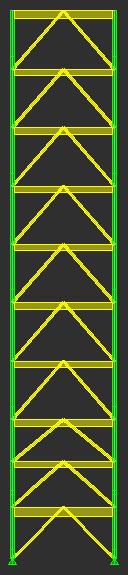
14 Figure B Wind pressure diagram for East-West direction Figure B shows the wind pressure diagram for the East-West direction. The windward loads are on the left, and the leeward loads are on the right. Figure C shows the wind force diagram and the base shear the building experiences. Figure C Wind force diagram for East-West direction
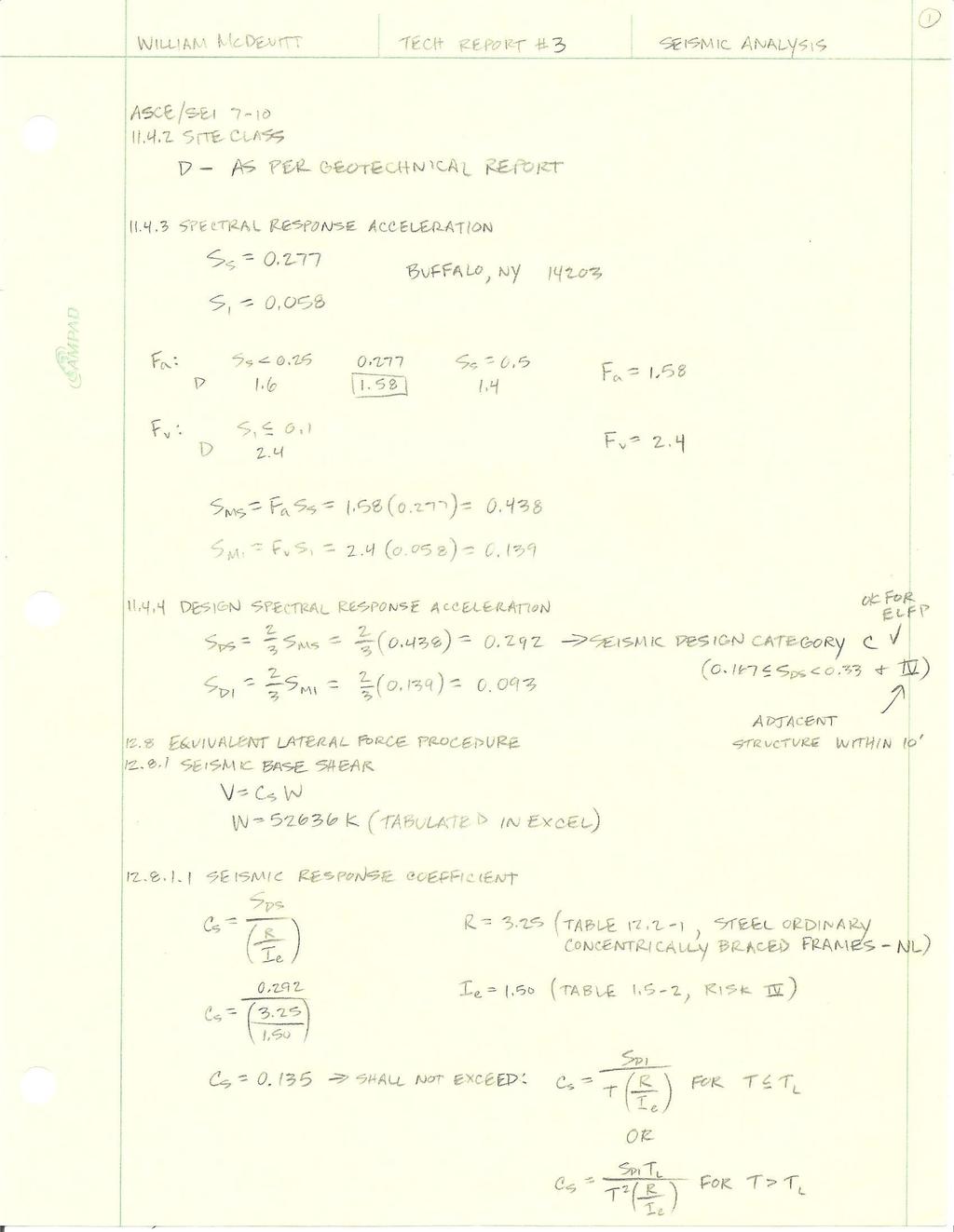
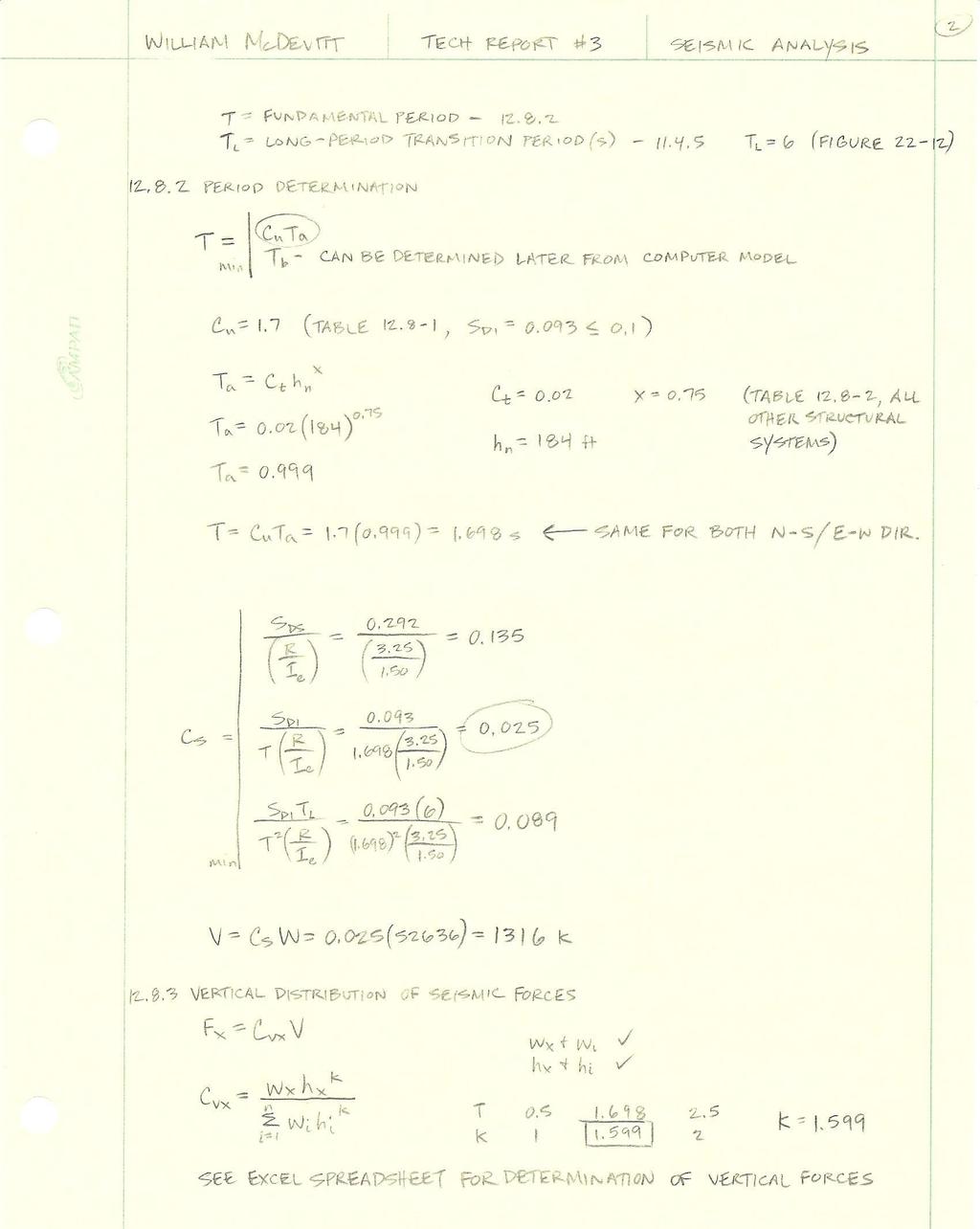
15 Seismic Loads Seismic analysis for GHVI was done in Technical Report 1, with reference to Chapters 11 and 12 in ASCE Minor changes were made for this report, however the building was still assumed to be square for simplicity. The first step in this analysis was the estimated summation of the entire building weight above grade, which included the beams, columns, composite slab, exterior walls, superimposed dead load, and partitions of each level. An Excel spreadsheet was set up to go through the building floor-by-floor and estimate as precisely as possible the building weight. The estimated building weight was found to be kips. The Equivalent Lateral Force Procedure was then used to determine the base shear and this base shear was then distributed to the diaphragm of each level as seen in Table 2. A more detailed set of calculations can be found in Appendix C. Level h i (ft) h (ft) w (k) w*h k C VX f i (k) V i (k) M i (ft-k) Roof Mechanical Basement Σ = Table 2 Seismic Design Loads Table 2 shows a total base shear of 1316 kips, and an overturning moment of foot-kips. The design engineers calculated a base shear of 1030 kips using ASCE The difference in these two numbers can be attributed to the fact that the design engineers used a smaller total building weight, but more importantly because the response modification factor for steel ordinary concentrically braced frames was 5 in ASCE 7-02, and is now 3.25 in ASCE A lower R value results in a more conservative number, hence a higher base shear
16 Snow Loads Snow loading for GHVI was calculated based on Chapter 7 in ASCE A ground snow load of 50 psf was determined from a site-specific case study provided by Cannon Design. The exposure factor, thermal factor, and importance factor were then obtained from the code and used to calculate the flat roof snow load of 42 psf, which matched the value obtained by the design engineers. Because part of the roof is lower than the rest of the building, drift calculations were performed to find the maximum snow loading in these areas. The detailed calculations for snow loading can be found in Appendix D

17 Computer Model In order to analyze the lateral system of GHVI a computer model was created using ETABS. This model was used for both 2D and 3D analysis. The structure as a whole was examined with a 3D model to determine how it would react to various load types and combinations. Also, each frame was studied in two dimensions to determine the relative stiffness. The steel columns and braces of the building were modeled by assigning material and frame section properties as per the structural plans. Columns were pinned at the base after careful consideration and consultation with the design structural engineer. Major and minor moments (M33 & M22) were released at the start and end of all beams. Braces were released of major and minor moment (M33 & M22) at the bottom, and major moment, minor moment, and torsion (M33, M22, & T) at the top to reduce out of plane bending. Finally, rigid diaphragms were drawn at each level and assigned with additional area masses to account for the weight of each floor. Hand calculations were conducted to verify the accuracy of the computer model, and it proved extremely helpful in visualizing how the structure actually works. The image below shows the 3D model that was used in analysis
18 Lateral System Analysis Relative Stiffness of Lateral Elements The relative stiffness of each frame was calculated for both the North-South and East-West directions, and is shown in the tables below. Finding the relative stiffness of each frame provides a reasonable method of distributing the lateral load throughout the building. It was done by placing a 100 kip load at the top of each individual frame, and then measuring the lateral displacement in inches. The formula for stiffness is: where k i is the stiffness, P is the force, or 100 kips, and d is the lateral displacement. After the stiffness for each frame was found, they were summed, and used to find the relative stiffness with the equation: Refer to Appendix E for a hand calculated lateral load distribution. East-West Direction Relative Stiffness Frame Load (k) Displacement (in) Stiffness (k/in) Relative Stiffness A C G E E E-15 H H Σ = Table 3 East-West Relative Stiffness North-South Direction Relative Stiffness Frame Load (k) Displacement (in) Stiffness (k/in) Relative Stiffness Σ = Table 4 North-South Relative Stiffness
19 Center of Rigidity The center of rigidity was calculated for each floor using the relative stiffness of each frame and the following equations: Table 5 displays the hand calculations for the center of rigidity at each floor, which were then compared to the values from ETABS, as shown in Table 6. Because the hand calculations are similar for most of the floors, it can be concluded that the ETABS values can be used with confidence. Hand Calculated Center of Rigidity Level X r Y r Roof Mechanical Basement Table 5 Hand Calculated COR ETABS Center of Rigidity Level X r Y r Roof Mechanical Basement Table 6 ETABS COR
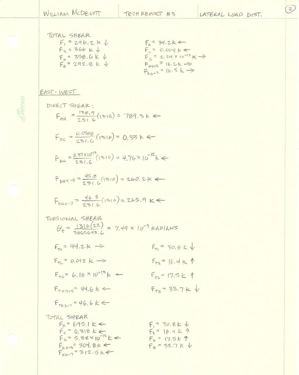
20 Center of Mass and Center of Pressure Both the center of mass and the center of pressure values were obtained for each floor from the ETABS model, and are shown in the tables below. These are important because earthquake forces act at the center of rigidity, and wind forces act at the center of pressure. If the center of rigidity or the center of pressure differs from the center of mass, a torsional force is induced from the eccentricity. As it can be seen from the Tables 6, 7, and 8, the centers of rigidity and pressure are in fact different from the center of mass, and thus torsion must be considered. Refer to Appendix E for detailed torsional shear hand calculations. Center of Mass Level X r Y r Roof Mechanical Basement Table 7 Center of Mass Center of Pressure Level X r Y r Roof Mechanical Basement Table 8 Center of Pressure
21 Load Combinations There are the seven basic load combinations prescribed by ASCE 7-10 section that were considered for this building: 1) 1.4D 2) 1.2D + 1.6L + 0.5(L r or S or R) 3) 1.2D + 1.6(L r or S or R) + (L or 0.5W) 4) 1.2D + 1.0W + L + 0.5(L r or S or R) 5) 1.2D + 1.0E + L + 0.2S Controlling Load Combination 6) 0.9D + 1.0W 7) 0.9D + 1.0E In all, 13 different load cases were input into ETABS for analysis. Snow load was previously calculated and is larger than the roof live load and the rain load. Therefore, the snow load controlled in any combination that included these three load types. Also, in the combinations with wind or earthquake, both an East-West (X) direction and a North-South (Y) direction were considered. After checking the deflection of a point at the roof level, it can be concluded that combinations five and seven control the design of this building. These cases include the X and Y earthquake forces, which implies that seismic loading controls design. Combination five was used as the controlling case because it would have a greater impact on the gravity system as well. Refer to Table 9 below for the deflections under each load combination. Level Diaphragm Load UX UY Roof D Roof D Roof D Roof D Roof D Roof D Roof D Roof D Roof D Roof D Roof D Roof D Roof D Table 9 Roof Level Deflections under Load Combinations
22 Drift Analysis Story drift and total drift were determined for the controlling seismic loading and wind loading. Checking seismic drift is necessary from a strength standpoint, in order to prevent building damage or failure. Wind drift is a serviceability issue, and addressing it is necessary to prevent sway that would cause discomfort to building occupants, as well as damage to curtain walls and other façade components. For seismic loading, drift values were obtained from the ETABS model and were then compared to the allowable story drift and total drift of 0.010h sx. The wind load drifts were also acquired from ETABS, but they were evaluated against the limit of H/400. As it can be seen from the following tables, all story drift and total drift values were well within the allowable limits. It was expected that drift would be acceptable when compared with code limits, but the large differences between code and modeled values may indicate a problem with the computer model. Further examination may be needed to assure that these values are in fact correct and no mistakes have been made. Controlling Seismic Drift: East-West Level Height (ft) Story Drift (in) Allowable Story Drift (in) Total Drift (in) Allowable Total Drift (in) Roof Acceptable Acceptable Acceptable Acceptable Acceptable Acceptable Acceptable Acceptable Acceptable Acceptable Acceptable Acceptable Acceptable Acceptable Acceptable Acceptable Acceptable Acceptable Acceptable Acceptable Mechanical Acceptable Acceptable Basement Acceptable Acceptable Table 10 East-West Direction Controlling Seismic Drift
23 Controlling Seismic Drift: North-South Level Height (ft) Story Drift (in) Allowable Story Drift (in) Total Drift (in) Allowable Total Drift (in) Roof Acceptable Acceptable Acceptable Acceptable Acceptable Acceptable Acceptable Acceptable Acceptable Acceptable Acceptable Acceptable Acceptable Acceptable Acceptable Acceptable Acceptable Acceptable Acceptable Acceptable Mechanical Acceptable Acceptable Basement Acceptable Acceptable Table 11 North-South Direction Controlling Seismic Drift Wind Drift: East-West Level Height (ft) Story Drift (in) Allowable Story Drift (in) Total Drift (in) Allowable Total Drift (in) Roof Acceptable Acceptable Acceptable Acceptable Acceptable Acceptable Acceptable Acceptable Acceptable Acceptable Acceptable Acceptable Acceptable Acceptable Acceptable Acceptable Acceptable Acceptable Acceptable Acceptable Mechanical Acceptable Acceptable Basement Acceptable Acceptable Table 12 East-West Direction Wind Drift
24 Wind Drift: North-South Level Height (ft) Story Drift (in) Allowable Story Drift (in) Total Drift (in) Allowable Total Drift (in) Roof Acceptable Acceptable Acceptable Acceptable Acceptable Acceptable Acceptable Acceptable Acceptable Acceptable Acceptable Acceptable Acceptable Acceptable Acceptable Acceptable Acceptable Acceptable Acceptable Acceptable Mechanical Acceptable Acceptable Basement Acceptable Acceptable Table 13 North-South Direction Wind Drift
25 Overturning and Impact on Foundation Overturning moments are a result of wind and seismic loading, and cause the building to try and topple over. This toppling produces uplift in the foundation, and the foundation must be able to resist this uplift. The foundation of GHVI consists of steel helical piles with an allowable axial capacity of 342 kips. These piles are driven to refusal at about a depth of 82 to 87 feet. In order to check the foundation of this building against uplift the controlling load combination was placed on the ETABS model in both the East-West direction and the North-South direction. From the model the reactions at the base of the structure were found, and negative reactions were deemed significant. A negative reaction on the base means that there is a positive uplift force on the foundation. The location of each uplift occurrence was determined, and the foundation plan was referenced to determine the type of pile cap and the number of piles at this region. The axial load was calculated for this part of the foundation, and it was then compared to the uplift force. The foundation was found to be adequate for each location of uplift. Refer to Tables 14 and 15 for the uplift locations, forces, and corresponding axial capacities. Level Point Load FZ Pile Cap Axial Capacity (k) Base Base Base PC Base PC Base Base Base PC Base Base PC7A 2394 Base PC Base PC Base Base Base Base Base Base Base Base Base PC Base Base PC Table 14 North-South Base Reactions and Corresponding Pile Axial Capacity
26 Level Point Load FZ Pile Cap Axial Capacity (k) Base Base Base PC Base Base Base Base Base PC Base PC7A 2394 Base Base PC Base Base PC Base Base Base PC Base Base Base Base Base Base Table 15 East-West Base Reactions and Corresponding Pile Axial Capacity

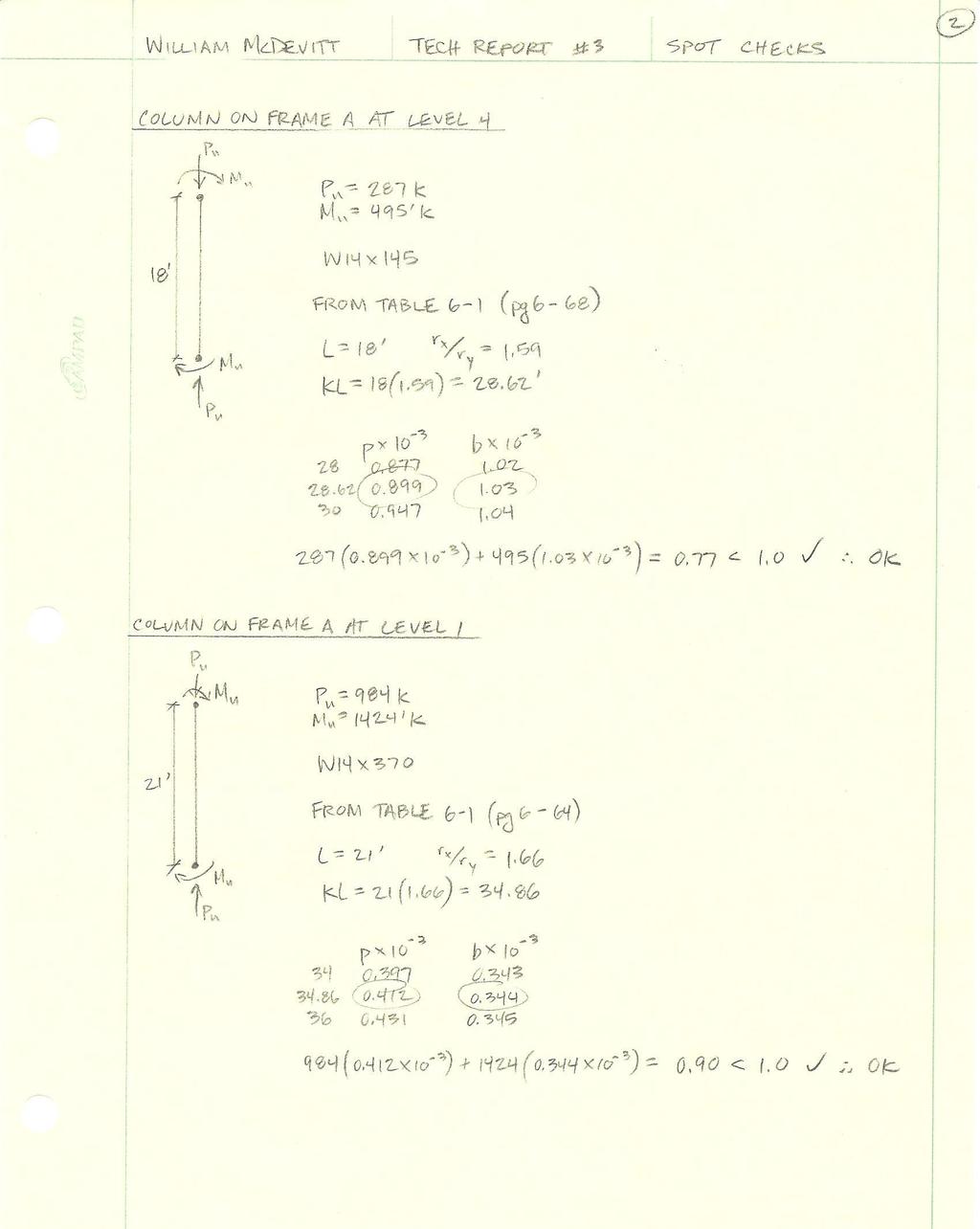
27 Lateral Member Spot Checks Lateral member spot checks were performed on three braces and two columns at different levels of Braced Frame A, as shown in Figure D. A brace was analyzed at the top, middle, and base of the structure, and a column was investigated at the middle and base of the structure. The loads for each member were obtained from the ETABS model considering the controlling load combination. All five members seem to be slightly oversized, and this may be a result of drift requirements. Detailed hand calculations of these spot checks can be found in Appendix F. Figure D Frame A
28 Conclusion This third technical report has investigated the existing lateral system of the Kaleida Health and University at Buffalo Global Heart and Vascular Institute with respect to strength and serviceability requirements. An ETABS model was constructed and used to study the building in both two and three dimensions. The steel columns and braces of each frame were modeled and assigned material and frame section properties. Columns were pinned at the base and beams and braces were released to prevent them from taking out-of-plane bending. A rigid diaphragm was drawn with additional area masses to model each floor level. Hand calculations were also conducted to verify the accuracy of the computer model. Seven basic load combinations were taken from ASCE 7-10 and considered to determine the controlling load case for this building. Due to the fact that combinations with wind or earthquake include both a North-South (Y) and an East- West (X) direction, 13 load cases were actually input into the ETABS model. Although unexpected, seismic loading was shown to control in both the North-South and East-West directions. The drift analysis included a strength check of the controlling seismic load combination, and a serviceability check of the wind forces acting on the building. Seismic drift values were obtained from the ETABS model and were checked against the allowable story drift and total drift of 0.010h sx. The wind load drifts were also acquired from ETABS, but they were evaluated against the limit of H/400. All story drift and total drift values were within the allowable limits, and although this was expected, the large differences between code and modeled values may indicate a problem with the computer model. Further investigation into the computer model and drift values may be required in a future report. Overturning moments were considered with regard to the foundations. The controlling seismic load combination was applied to the ETABS model and uplift forces were found at the base of some of the frames. After checking all critical points at the base of the structure, the foundation was found to be adequately designed for uplift. Five lateral spot checks were performed on columns and braces in Frame A. Because Frame A resists lateral load in the East-West direction, the controlling East-West seismic load combination was used to determine the loads. A brace was analyzed at the top, middle, and base of the structure, and a column was investigated at the middle and base of the structure. Hand calculations were performed and all five of the members were found to be sufficient
29 Appendix

30 Appendix A: Typical Floor Plans and Elevations Figure E Site Plan (Cannon Design)
31 Figure F Typical floor framing plan (Cannon Design)

32 Figure G West Elevation (Cannon Design)
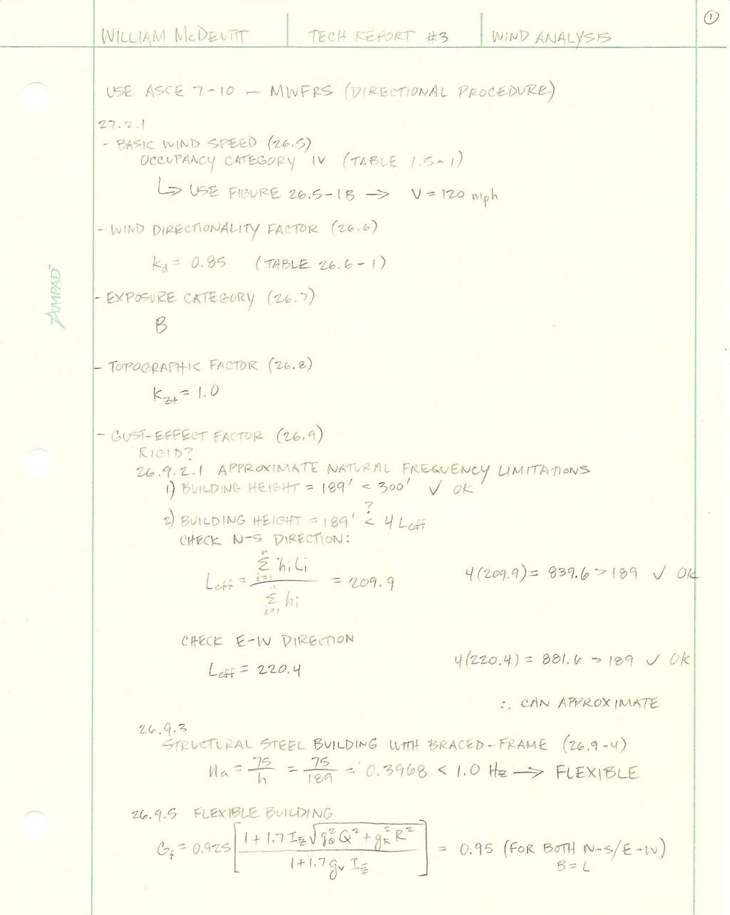
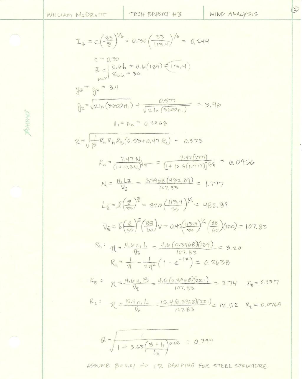
33 Appendix B: Wind Analysis The following table contains the initial parameters used in the wind analysis as determined from ASCE 7-10: V 120 K d 0.85 Exposure B K zt 1 GC pi 0.18 Table 16 - Parameters The following table contains the effective length calculations completed to assure that the natural frequency could be approximated: N-S Direction E-S Direction Level h i l i h i l i Level h i l i h i l i Sub basement Sub basement Basement Basement Mechanical Mechanical Σ = Σ = L eff = L eff = Table 17 Effective Length Check Calculations
34 The following table contains the calculations to determine the gust-effect factor: Gust Effect Calculation N-S E-W B L h n a FLEXIBLE FLEXIBLE I z c z g Q g v g R R R n N L z V z R h n R B n R L n Q β G f Table 18 Gust Effect Calculations The following table contains the wind pressure coefficients: Wind Pressure Coefficients Surface L/B Cp Use With Windward All 0.8 q z Leeward q h Side All -0.7 q h Table 19 Wind Pressure Coefficients
35 The following tables contains the wind pressure in pounds per square feet for both the windward and leeward directions: Windward Level Height (ft) K z q z Wind Pressure N-S E-W Top of Parapet Upper Roof Mechanical Basement Table 20 Windward Wind Pressures Wind Pressure Level q h N-S E-W Top of Parapet Leeward Remaining Table 21 Leeward Wind Pressures
36 - 35 -
37 - 36 -
38 - 37 -
39 Appendix C: Seismic Analysis The following table contains an example summation of the weight of a floor for use in seismic analysis: Level 6 Steel-Beams Type Number Length(ft) Weight (lb/ft) Weight (lb) W27x W30x Total Beams Steel-Columns Type Number Length(ft) Weight (lb/ft) Weight (lb) W14x W14x W14x W14x W14x Total Columns Deck Type Weight (psf) Area (ft2) Weight (lb) 3" (7.5") Total Deck Total L6 Weight (lb) Table 22 Example Weight Summation The following table contains the summation of the total building weight above grade: Level Weight (k) Roof Base/Mech 2478 Total Table 23 Total Weight
40 - 39 -
41 - 40 -

42 Appendix D: Snow Loading

43 Appendix E: Lateral Load Distribution
44 - 43 -

45 Appendix F: Lateral Member Spot Checks
46 - 45 -