DESIGN STANDARDS DEVELOPMENT REPORT FOR CORROSION RESISTANT PRESTRESSED CONCRETE PILES (INDEX No Series FY Design Standards)
|
|
|
- Beverley Agatha Merritt
- 5 years ago
- Views:
Transcription
 NEED: The current prestressed concrete pile standards (Index 20600 thru 20660) provide standard square and cylinder concrete pile shapes and sizes for bridge")

1 FDOT Design Standards Development Report Proposed Index No DESIGN STANDARDS DEVELOPMENT REPORT FOR CORROSION RESISTANT PRESTRESSED CONCRETE PILES (INDEX No Series FY Design Standards) NEED: The current prestressed concrete pile standards (Index thru 20660) provide standard square and cylinder concrete pile shapes and sizes for bridge foundation systems. These piles utilize uncoated carbon steel prestressing strands and spiral confinement ties that rely on concrete cover and supplemental cementitious materials to provide a barrier to chloride ingress. Within uncracked concrete this concrete densification coupled with the alkaline environment provided by the portland cement, delays the diffusion of chloride ions to the depth of the reinforcing which would result in the initiation of corrosion and subsequent deterioration of the pile. A standard pile option using corrosion resistant prestressing and reinforcement would provide corrosion resistance that did not rely on the concrete cover, densification or alkalinity of the concrete component. This is especially important for marine environments or when concrete cracking is expected due to hard driving conditions during installation or high flexural loads during the service life of the foundation. BACKGROUND: FDOT introduced precast concrete piles in the 1930 s (see Figures 1 & 2) and prestressed piles in the mid 1950's (see Figure 3). These have been standardized in the published Structures Standards since the 1979 (see Attachment A ) and later published as Design Standards in Incremental improvements in the pile design have occurred through the history of their usage in Florida, but they typically remain the first elements to deteriorate on bridges in marine environments, resulting in the need for expensive repairs and mitigation through pile jacketing, cathodic protection and/or construction of replacement crutch bents. Figure 1: Precast Concrete Pile form Index No. 889 (1932) Figure 2: Precast Concrete Pile from Index No (1937) November 2015 (revised February 2016) Page 1
 Several researchers [1] [2] [3] have investigated the use of inert or corrosion resistant prestressing strands such as carbon-fiber reinforced polymers (CFRP) or stainless steel (SS).")
2 FDOT Design Standards Development Report Proposed Index No Figure 3: Prestressed Concrete Pile from Index No (1954) Several researchers [1] [2] [3] have investigated the use of inert or corrosion resistant prestressing strands such as carbon-fiber reinforced polymers (CFRP) or stainless steel (SS). FDOT currently has a Developmental Design Standard for CFRP prestressed piles under the D22600 series. The 14" square piles are intended as an option for bridge fender systems and the 24" square CFRP prestressed piles where developed for a pilot project (FPID Halls River Bridge Replacement) scheduled for construction in During final design the pile size was reduced to an 18" square pile for economy, when the Structures Design Guidelines SDG F requirement for a minimum 24" square pile size in marine environments was deemed not applicable for a corrosion resistant pile. PROPOSED DESIGN: The proposed new pile standards will utilize both options of CFRP and SS prestressed strands and spirals. These materials are significantly more expensive than conventional ASTM A416 prestressing strand and ASTM A82 or A1064 wire. However by standardizing their usage and providing the Contractor with the equal substitution options for CFRP or SS, market forces should eventually reduce the initial material costs. Materials selected from both options are intended to provide a maintenance free service life of 100+ years resulting in life cycle cost savings (see Attachment "B"). The initial usage will be restricted to the most severe corrosion conditions which is in the splash zone of extremely aggressive (marine) environments due to chlorides. Therefore these standards will be mandated for use on intermediate pile bents in marine environments wherever prestressed concrete piles are identified as the optimal foundation component in the Bridge Development Report (BDR). CFRP prestressing strands are available in many sizes but most have a limited supply and long lead times. 0.5-inch diameter single wire and 0.60-inch diameter 7-wire strand were identified as the most economical and commercially viable strand sizes during development of the DDS Index D22600 series in 2014, resulting in two strand pattern configurations for each pile size. High Strength Stainless Steel (HSSS) prestressing strand is currently commercially available in 0.5-inch diameter 7-wire strand in the UNS S32205/S31803 material that is preferred due to its enhanced corrosion resistant to chloride attack [1][2] over other HSSS materials such as S30400 or S31603 (Type 304 or 316L) in the a low stress condition. UNS S30400 was selected as an economical material for the spiral ties to avoid the potential for galvanic corrosion and still provide good corrosion resistance in the non-prestressed condition. Due to the reduction in the elastic modulus of SS compared to conventional carbon steel wire, the size of the SS spirals is specified slightly larger (W4.0) than the spirals on Index series (W3.4) to compensate for some of the loss in elastic confinement while maintaining the same spiral pitch. FDOT prestressed concrete pile designs are usually governed by the requirement for a minimum precompression force of 1,000 psi to minimize the potential for cracking during handling and driving. The November 2015 (revised February 2016) Page 2
3 FDOT Design Standards Development Report Proposed Index No piles obviously need to satisfy any axial, flexural or shear demands imposed by the design loads, but these are usually secondary due to Florida's predominantly granular soils. Skin friction usually dictates the pile embedment depth due to the lack of shallow rock strata in much of the central and northern portions of Florida. There are maximum recommended axial capacities provided in SDG Table well below the pile ultimate axial capacity, which are intended to mitigate the potential for damage under hard driving conditions. Therefore piles are usually larger in cross section than may be necessary under a flexure-controlled design, providing additional surface area to achieve axial capacity without the need for excessively long piles; which may be difficult to handle and transport. For these reasons, the strategy for designing standard piles for the Design Standards, has been to provide a minimum 1,000 psi pre-compression in the pile during installation. Installation is assumed to be at 120 days, with the associated losses accounted for in the calculations using either the Approximate or Refined Losses Methods in LRFD & LRFD An upper pre-compression limit of 1100 psi is used to provide consistency between different optional strand pattern configurations. To achieve this 1000 psi to 1100 psi range, jacking forces are often less than the maximum limit allow by LRFD Table Since the AASHTO-BDS does not address CFRP or SS prestressing strands, additional design guidance is necessary. CFRP Prestressing Designs: ACI 440.4R is a nationally recognized consensus design guide for FRP prestressing and was utilized for the DDS Index D22600 series designs. CFRP is the only material type that FDOT is currently permitting for FRP prestressed designs. The upper limit for jacking stresses is established at 65% of the ultimate tensile strength (UTS) of the strand, although recent research [5] and demonstration projects [6] has suggested that much higher limits are possible. A 70% UTS upper limit will be utilized on future revisions to these Indexes to improve economy of the 12 and 24 pile sections. The 0.9 environmental factor (C E) is not applied to this temporary limit due to the relatively short term stress condition, since creep rupture and other long term stress checks are presumed to guard against any long-term over-stressing effects. Ultimate pile capacity moment axial (M-N) interaction curves using and C E = 0.9 are developed and provided in the IDS. The capacities are based on the long-term losses from both the strand relaxation and concrete creep, shrinkage and elastic shortening. Strand relaxation losses are assumed to be 3% of the jacking force based on guidance in ACI 440.4R. Concrete losses are calculated in accordance with the AASHTO-BDS. For independent verification of the substructure capacity, designers must assume linear stress-strain effects in the strand up to rupture at the UTS. The ACI design guide has reduced resistance factors to account for the reduced ductility that may occur with FRP strands. The resistance factors range for 0.65 to 0.85 for tension-controlled to compression-controlled failure modes. The pile splice designs utilize non-prestressed bars and as such are covered by the ACI 440.1R design guide with different design criteria. It is not feasible to provide a splice design that meets 100% of the prestressed capacity of the pile, so 85% was set as the target limit using CFRP bars. #6 bars were chosen as the splice-dowel bars due to availability and optimal capacity. Reduction in effective bar stress capacity (and economy) occurs when using larger bar sizes due to lower fiber fractions. SS Prestressing Designs: High strength stainless steel (HSSS) strand design is currently not addressed in AASHTO-BDS or ACI. The production of HSSS strand is not covered by an ASTM fabrication standard, but the material components are specified in ASTM A276. Stainless steel bar specifications are available November 2015 (revised February 2016) Page 3

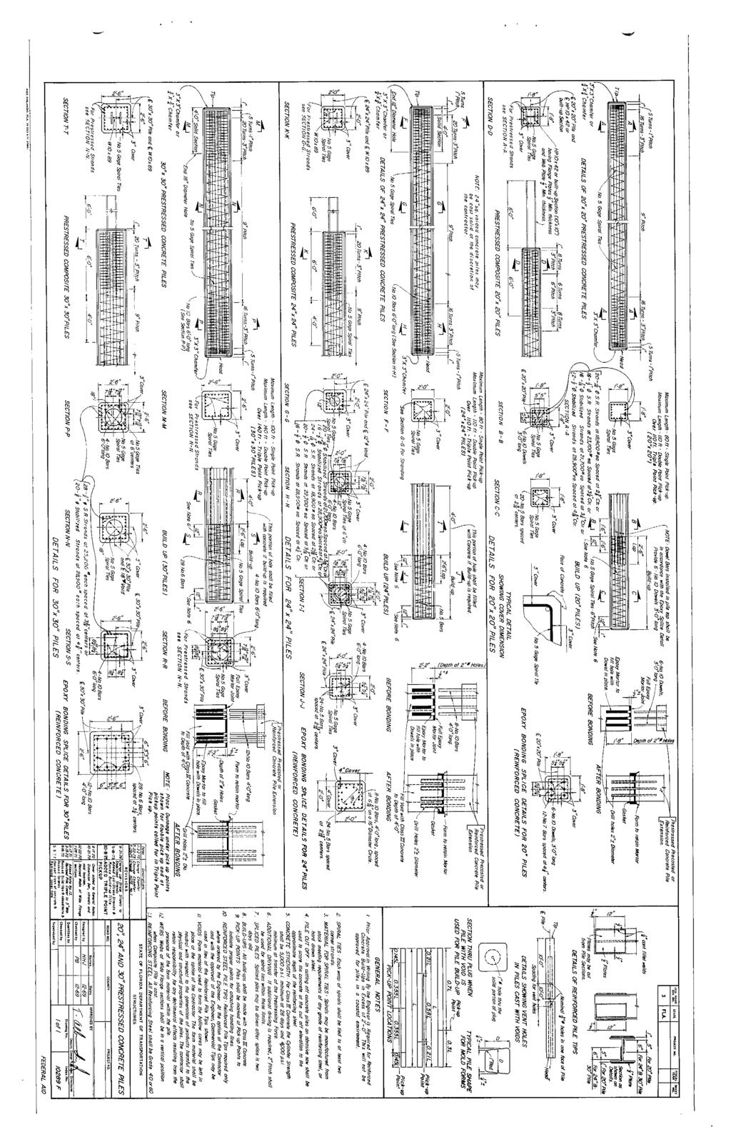
4 FDOT Design Standards Development Report Proposed Index No in both AASHTO M13 and ASTM A955. FDOT is using the recommendations from Report No. FHWA-GDOT-GT [1] for the design of SS prestressed piles. The recommendations within this report state that prestressed losses, transfer and development lengths can utilize the same equations in AASHTO-BDS that are applied to carbon-steel strand. The UTS for S32205 strand was based on ksi for the design and testing. The author s recommendation is to conservatively use 240 ksi for the development of M-N Interaction curves. The recommended jacking stress limits of 70% UTS, have been adopted for the SS prestressed pile designs under Index series. Pile splice design is similar to Index except a smaller bar sizes could be utilized due to the higher yield strength (75 ksi) of the SS dowel reinforcing. Standard Drawings: The CR-prestressing standards will be issued under the Index series to distinguish them from the conventionally prestressed piles (Index series). The format will be the same except that there will be one detail sheet for CFRP prestressed piles and one sheet for SS prestressed piles under each Index number based on pile size as shown below: Index Notes and Details for Square CFRP & SS Prestressed Concrete Piles; Index Square CFRP & SS Prestressed Concrete Pile Splices; Index '' Square CFRP & SS Prestressed Concrete Pile; Index '' Square CFRP & SS Prestressed Concrete Pile; Index '' Square CFRP & SS Prestressed Concrete Pile; Index '' Square CFRP & SS Prestressed Concrete Pile; Index '' Square CFRP & SS Prestressed Concrete Pile; Index '' Precast/Post-Tensioned CFRP & SS Concrete Cylinder Pile; Index '' Prestressed CFRP & SS Concrete Cylinder Pile. The 20 pile will not be issued due to lack of historical use Florida based on recent surveys with producers and District Materials. The High Moment Capacity 30 Pile (Index 20631) will not be issued in a CR-prestressed version at this time due to the perceived lack of need since these standards will only be required on pile bents in extremely aggressive environments which typically do not have high flexural demands. Typical Prestressing Strand Patterns: Table 1: Square Prestressed Concrete Piles strand pattern comparison November 2015 (revised February 2016) Page 4


5 FDOT Design Standards Development Report Proposed Index No Table 2: CFRP Prestressed Concrete Cylinder Piles strand patterns Table 3: HSSS Prestressed Concrete Cylinder Piles strand patterns ESTIMATED COST: There will be an additional cost for the use of either CFRP or SS strand and spirals. Current estimates for material costs range from $3.50 to $10 per linear foot for 0.5" diameter strand with more variability in the CFRP presumably due to this being an emerging technology. $4.00/LF of strand should be assumed for initial cost estimates. Given that conventional steel strand costs approximately $1.00/LF, then for BDR cost estimating proposes an additional $3.00/LF of strand should be used. Attachment "C" provides tables of estimate costs for the various pile sizes and strand patterns shown in the proposed Index series based on these premiums. OTHER AFFECTED DOCUMENTS: 1. Structures Manual: SDG 3.5, see Attachment "D"; 2. Instructions for Design Standards: New IDDS required, see Attachment E ; 3. Plans Preparation Manual: No changes are necessary; 4. Basis of Estimates Manual: A new pay item is recommend for corrosion-resistant prestressed piles, see Attachment F ; 5. Construction Specifications New specifications will be required for the stainless-steel strands, spirals and pile-splice dowel bars. Specification for the CFRP strands, spiral and pile-splice dowel bars are already available as Developmental Specifications Dev400FRP, Dev416FRP, Dev932FRP, and Dev933FRP, but will need to be adopted as Supplemental Specifications and add SS to Section 931 for full implementation. November 2015 (revised February 2016) Page 5
6 FDOT Design Standards Development Report Proposed Index No IMPLEMENTATION PLAN: Publishing of a Structures Design Bulletin in December 2015 is recommended to advise the design community of the impending change in policy. Publishing of the Design Standards could be completed by January 1, 2016 for implementation on projects with lettings beginning July Standard Specifications will need immediate attention to ensure meeting the July 2016 Specifications Workbook. Accelerated implementation for use on Design-Build projects beginning with Advertisements in January 2016 could be possible as an option to the Design-Build teams for providing enhancements to their proposals with the goal of reducing long term maintenance costs. REFERENCES: 1. Paul A, Kahn L.F, Kurtis K.E, (2015). Corrosion-Free Precast Prestressed Concrete Piles Made with Stainless Steel Reinforcement: Construction Test and Evaluation, Report No. FHWA-GA , Georgia Institute of Technology, for Georgia Department of Transportation, March Mullins G, Sen R, (2014). Design and Construction of Precast Piles with Stainless Reinforcing Steel, Report No. BDK , University of South Florida, for Florida DOT, February rpt.pdf 3. Roddenberry M, Mtenga P, Joshi K, (2014). Investigation of Carbon Fiber Composite Cables (CFCC) in Prestressed Concrete Piles, FAMU-FSU College of Engineering, for FDOT Project BDK , April BDK rpt.pdf 4. Joshi K.S, (2013), Investigation of Carbon Fiber Composite Cables (CFCC) in Prestressed Concrete Piles, Florida State University, FAMU-FSU College of Engineering, Masters Thesis, Nov Mirmiran, A. (ongoing). Use of Fiber Reinforced Polymer Composite Cable for Post-Tensioning Applications Phase 2, Florida International University, for FDOT Project BDV , Nanni, A (2016). Hecht Pedestrian Bridge FHWA Every Day Counts Initiative, University of Miami, Civil, Architecture & Environmental Engineering Department, January Report Prepared By: Steven Nolan P.E. State Structures Design Office (Design Technology Group) November 16th, 2015 Revised February 3 rd, 2016 November 2015 (revised February 2016) Page 6
7 FDOT Design Standards Development Report Proposed Index No ATTACHMENT A Historical Structures Standards for Prestressed Concrete Piles from 1979 November 2015 (revised February 2016) Page 7
8
9
10 FDOT Design Standards Development Report Proposed Index No ATTACHMENT B Life Cycle Cost Analysis Example Pending November 2015 (revised February 2016) Page 8
11 FDOT Design Standards Development Report Proposed Index No ATTACHMENT C Table of Estimated Costs for CFRP & SS Prestressed Piles November 2015 (revised February 2016) Page 9
12 FDOT Design Standards Development Report Proposed Index No ATTACHMENT D Structures Manual Changes November 2015 (revised February 2016) Page 10
13 FDOT Design Standards Development Report Proposed Index No ATTACHMENT C Table of Estimated Costs for CFRP & SS Prestressed Piles November 2015 (revised February 2016) Page 9
14 FDOT Design Standards Development Report Proposed Index No ATTACHMENT D Structures Manual Changes November 2015 (revised February 2016) Page 10
15 FDOT Design Standards Development Report Proposed Index No ATTACHMENT E Proposed Instructions for Design Standards IDS IDS IDS November 2015 (revised February 2016) Page 11
16 Instructions for Design Standards Topic No Index Series Square CFRP & SS Prestressed Concrete Piles (Rev. 01/16) FY Index Series Square CFRP & SS Prestressed Concrete Piles (Rev. 01/16) Design Criteria AASHTO LRFD Bridge Design Specifications; Structures Design Guidelines (SDG); Structures Detailing Manual (SDM); Fiber Reinforced Polymer Guidelines (FRPG) Design Assumptions and Limitations Index is the lead standard for the Square CFRP & SS Prestressed Concrete Pile standard series which includes Indexes through Use this standard with Indexes 22601, 20602, 22612, 22614, 22618, and Standard piles are designed to have 1000 psi uniform compression after prestress losses without any applied loads to offset tensile stresses that occur during typical driving. The piles are designed to have 0.0 psi tension using a load factor of 1.5 times the pile self weight during pick-up, storage and transportation as shown in the "Table of Maximum Pile Pick-Up and Support Lengths" on the standard. Plan Content Requirements In the Structures Plans: Show and label the piles on the Foundation Layout, End Bent, Intermediate Bent, Pier, Footing, Typical Section and other sheets as required. Complete the following "Data Table" in accordance with SDG 3.5 and SDM 11.4 and include it in the contract plans with the "Foundation Layout" sheets. Modify table and notes as required to accommodate the required number of piles, piers and/or bents, use of Test Piles and instrumentation. When not enough space is available on one plan sheet, continuations of the Data Table and/or separate pile cut-off elevation tables are acceptable. See Introduction I.3 for more information regarding use of Data Tables. For projects without Test Piles change data table column heading "TEST PILE LENGTH (ft.)" to "PILE ORDER LENGTH (ft.)". 327
17 Instructions for Design Standards Topic No Index Series Square CFRP & SS Prestressed Concrete Piles (Rev. 01/16) FY
18 Instructions for Design Standards Topic No Index Series Square CFRP & SS Prestressed Concrete Piles (Rev. 01/16) FY Payment Item number Item description Unit Measure AA Prestressed Concrete Piling (CFRP or SS) LF Design Aids ϕ ϕ 329
19 Instructions for Design Standards Topic No Index Series Square CFRP & SS Prestressed Concrete Piles (Rev. 01/16) FY ϕ ϕ 330
20 Instructions for Design Standards Topic No Index Series Square CFRP & SS Prestressed Concrete Piles (Rev. 01/16) FY ϕ ϕ 331
21 Instructions for Design Standards Topic No Index Series Square CFRP & SS Prestressed Concrete Piles (Rev. 01/16) FY ϕ ϕ 332
22 Instructions for Design Standards Topic No Index Series Square CFRP & SS Prestressed Concrete Piles (Rev. 01/16) FY ϕ ϕ 333
23 Instructions for Design Standards Topic No Index " Prestressed / CFRP & SS Post-Tensioned Concrete Cylinder Pile (Rev. 01/16) FY Index " Prestressed / CFRP & SS Post-Tensioned Concrete Cylinder Pile (Rev. 01/16) Design Criteria AASHTO LRFD Bridge Design Specifications, 6th Edition; Structures Design Guidelines (SDG); Structures Detailing Manual (SDM); Fiber Reinforced Polymer Guidelines (FRPG) Design Assumptions and Limitations Standard piles are designed to have 1000 psi uniform compression after prestress losses without any applied loads. The piles are designed to have 0.0 psi tension using a load factor of 1.5 times the pile self weight during pick-up, storage and transportation as shown in the "Table of Maximum Pile Pick-Up and Support Lengths" on the standard. Plan Content Requirements In the Structures Plans: Show and label the piles on the Foundation Layout, End Bent, Intermediate Bent, Pier, Footing, Typical Section and other sheets as required. Complete the following "Data Table" in accordance with SDG 3.5 and SDM 11.4 and include it in the contract plans with the "Foundation Layout" sheets. Modify table and notes as required to accommodate the required number of piles, piers and/or bents and use of Test Piles. When not enough space is available on one plan sheet, continuations of the Data Table and/or separate pile cut-off elevation tables are acceptable. See Introduction I.3 for more information regarding use of Data Tables. For projects without Test Piles change column heading "TEST PILE LENGTH (ft.)" to "PILE ORDER LENGTH (ft.)". 334
24 Instructions for Design Standards Topic No Index " Prestressed / CFRP & SS Post-Tensioned Concrete Cylinder Pile (Rev. 01/16) FY
25 Instructions for Design Standards Topic No Index " Prestressed / CFRP & SS Post-Tensioned Concrete Cylinder Pile (Rev. 01/16) FY Payment Item number Item description Unit Measure Concrete Cylinder Piles Furnished & Driven (54" Diameter CFRP or SS) LF 336
26 Instructions for Design Standards Topic No Index " CFRP & SS Prestressed Concrete Cylinder Pile (Rev. 01/16) FY Index " CFRP & SS Prestressed Concrete Cylinder Pile (Rev. 01/16) Design Criteria AASHTO LRFD Bridge Design Specifications, 6th Edition; Structures Design Guidelines (SDG); Structures Detailing Manual (SDM); Fiber Reinforced Polymer Guidelines (FRPG) Design Assumptions and Limitations Standard piles are designed to have 1000 psi uniform compression after prestress losses without any applied loads. The piles are designed to have 0.0 psi tension using a load factor of 1.5 times the pile self weight during pick-up, storage and transportation as shown in the "Table of Maximum Pile Pick-Up and Support Lengths" on the standard. Plan Content Requirements In the Structures Plans: Show and label the piles on the Foundation Layout, End Bent, Intermediate Bent, Pier, Footing, Typical Section and other sheets as required. Complete the following "Data Table" in accordance with SDG 3.5 and SDM 11.4 and include it in the contract plans with the "Foundation Layout" sheets. Modify table and notes as required to accommodate the required number of piles, piers and/or bents and use of Test Piles. When not enough space is available on one plan sheet, continuations of the Data Table and/or separate pile cut-off elevation tables are acceptable. See Introduction I.3 for more information regarding use of Data Tables. For projects without Test Piles change column heading "TEST PILE LENGTH (ft.)" to "PILE ORDER LENGTH (ft.)". 337
27 Instructions for Design Standards Topic No Index " CFRP & SS Prestressed Concrete Cylinder Pile (Rev. 01/16) FY
28 Instructions for Design Standards Topic No Index " CFRP & SS Prestressed Concrete Cylinder Pile (Rev. 01/16) FY Payment Item number Item description Unit Measure Concrete Cylinder Piles Furnished & Driven (60" Diameter CFRP or SS) LF 339

29 FDOT Design Standards Development Report Proposed Index No ATTACHMENT F Proposed Basis of Estimate Manual Changes The following new Pay Items should be available in July 2016 lettings: November 2015 (revised February 2016) Page 12