Sentry Stucco Ultra Wall System
|
|
|
- Oswin Hampton
- 5 years ago
- Views:
Transcription

1 Typical Details Sentry Stucco Ultra Wall System Premium impact and puncture resistant, rain screen design cement plaster stucco system with enhanced water management 1. Typical Sentry Stucco Ultra Wall System with Steel Framing 2. Typical Sentry Stucco Ultra Wall System with Wood Framing 3. Typical Sentry Stucco Ultra Wall System with CMU 4. Typical Surface Control Joint 5. Typical Expansion Joint 6. Typical Drainage at Floorline 7. Typical Clad Window Jamb 8. Typical Clad Window Head 9. Typical Clad Window Sill 10. Typical Primed Window Head 11. Typical Primed Window Jamb 12. Typical Primed Window Sill 13. Typical EPS Shape Application 14. Typical Termination at Soffit/Gable End 15. Typical Termination at Foundation 16. Typical Kick-out Flashing 17. Typical Termination at Deck 18. Typical Coping 19. Typical Corner Bead 20. Typical Downspout Application 21. Typical Pipe Penetration 22. Typical Light Fixture 23. Typical Dryer Vent


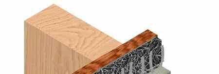
2 TYPICAL SENTRY STUCCO ULTRA WALL SYSTEM WITH STEEL FRAMING Ensure Senershield-R is dry prior to Drainage Mat DF installation. Install Drainage Mat DF with the fabric side facing out. SSU TYPICAL SENTRY STUCCO ULTRA WALL SYSTEM WITH WOOD FRAMING with installation instructions and applicable code. Wood based sheathing requires two coats of Senershield-R. It can be sprayed to a 20-mil thickness in one wet application. Ensure Senershield-R is dry prior to Drainage Mat DF installation. Install Drainage Mat DF with the fabric side facing out. SSU
3 with installation instructions and applicable code. Multiple coats of Senershield-R may be required to achieve a pin-hole free application. Ensure Senershield-R is dry prior to Drainage Mat DF installation. Install Drainage Mat DF with the fabric side facing out. TYPICAL SENTRY STUCCO ULTRA WALL SYSTEM WITH CMU SSU Provide control joints at a maximum 13.4 sq. m. (144 sq.ft.) and placement as determined by the design professional. Install per requirements of ASTM C1063. Lath must be broken at the joint accessory. TYPICAL SURFACE CONTROL JOINT SSU
4 TYPICAL EXPANSION JOINT Install expansion joints in the system at all changes in substrate, through existing expansion joints, and where movement is anticipated. It is the sole responsibility of the design professional to determine specific expansion joint location, placement and design. Install per requirements of ASTM C1063. Lath must be broken at the joint accessory. SSU TYPICAL DRAINAGE AT FLOORLINE Senershield-R shall be installed over flashing. Provide end-dams at flashing terminations as required. Lath must be broken at joint accessory. It is recommended that a means for drainage is provided at every floor. SSU
5 Ensure Senershield-R is properly applied into the rough openings in accordance with application guidelines. see Air/Water-Resistive/Vapor Barrier Application Guidelines technical bulletin. TYPICAL CLAD WINDOW - JAMB SSU Ensure Senershield-R is properly applied over the head flashing. Provide end-dams at flashing terminations TYPICAL CLAD WINDOW - HEAD SSU
6 TYPICAL CLAD WINDOW - SILL Ensure Senershield-R is properly applied into the rough openings in accordance with application guidelines. See Air/Water-Resistive/Vapor Barrier Application Guidelines technical bulletin. SSU TYPICAL PRIMED WINDOW - HEAD Ensure Senershield-R is properly applied over the head flashing. Provide end-dams at flashing terminations. SSU
7 Ensure Senershield-R is properly applied into the rough openings in accordance with application guidelines. See Air/Water-Resistive/Vapor Barrier Application Guidelines technical bulletin. TYPICAL PRIMED WINDOW - JAMB SSU Ensure Senershield-R is properly applied into the rough openings in accordance with application guidelines. See Air/Water-Resistive/Vapor Barrier Application Guidelines technical bulletin.. TYPICAL PRIMED WINDOW - SILL SSU


 over the Sentry")
8 TYPICAL EPS SHAPE APPLICATION Overlap reinforced base coat onto StuccoBase a minimum of 76 mm (3 ). On horizontal projections greater than one inch maintain a minimum 6:12 slope. SSU TYPICAL TERMINATION AT SOFFIT/GABLE END Lap frieze band a minimum of 50 mm (2 ) over the Sentry Stucco Ultra Wall System. SSU
9 Per ASTM C1063 terminate the Sentry Stucco Ultra Wall System a minimum of 100 mm (4 ) above raw earth and 50 mm (2 ) above paved surface. Senershield-R shall be installed over weep screed flange. TYPICAL TERMINATION AT FOUNDATION SSU Terminate Sentry Stucco Ultra Wall System a minimum of 50 mm (2 ) above roof. Ensure step flashing is a minimum 50 mm (2 ) behind Sentry Stucco Ultra Wall System. Kick-out flashing shall be a minimum 100 mm (4 ) in height. Kick-out flashing shall be angled a minimum 100-degrees with seams sealed or soldered. Ensure a means for drainage is provided at Sentry Stucco Ultra Wall System termination at roof. TYPICAL KICK-OUT FLASHING SSU
10 TYPICAL TERMINATION AT DECK Senershield-R shall be installed over flashing. Senershield-R shall be installed up and behind flashing before terminating. Provide end-dams at flashing terminations as required. SSU TYPICAL COPING with installation instructions and applicable code. Extend coping a minimum of 50 mm (2 ) on to face of Sentry Stucco Ultra Wall System and seal drip edge. Senershield-R shall be installed up and over the top and extended down the other side. SSU


11 Attach corner bead over lath. Corner bead shall be filled solid with StuccoBase, as required. TYPICAL CORNER BEAD SSU with installation instructions and applicable code. Properly seal all penetrations through the Sentry Stucco Ultra Wall System. TYPICAL DOWNSPOUT APPLICATION SSU


12 TYPICAL PIPE PENETRATION Properly seal all penetrations through the Sentry Stucco Ultra Wall System. SSU TYPICAL LIGHT FIXTURE with installation instructions and applicable code. Properly seal all penetrations through the Sentry Stucco Ultra Wall System. SSU
13 with installation instructions and applicable code. Properly seal all penetrations through the Sentry Stucco Ultra Wall System. TYPICAL DRYER VENT SSU
14 NOTES
15 NOTES
16 Note BASF Wall Systems is an operating unit of BASF Corporation (herein referred to as BASF Wall Systems ) Disclaimer This information and all further technical advice are based on BASF Wall Systems present knowledge and experience. However, BASF assumes no liability for providing such information and advice including the extent to which such information and advice may relate to existing third party intellectual property rights, especially patent rights. In particular, BASF Wall Systems disclaims any and all CONDITIONS AND WARRANTIES, WHETHER EXPRESS OR IMPLIED, INCLUDING THE IMPLIED WARRANTIES OF FITNESS FOR A PARTICULAR PURPOSE OR MERCHANTABILITY. BASF WALL SYSTEMS SHALL NOT BE RESPONSIBLE FOR CONSEQUENTIAL, INDIRECT OR INCIDENTAL DAMAGES (INCLUDING LOSS OF PROFITS) OF ANY KIND. BASF Wall Systems reserves the right to make any changes according to technological progress or further developments. It is the customer s responsibility and obligation to carefully inspect and test any incoming goods. Performance of the product(s) described herein should be verified by testing and carried out only by qualified experts. It is the sole responsibility of the customer to carry out and arrange for any such testing. Reference to trade names used by other companies is neither a recommendation, nor an endorsement of any product and does not imply that similar products could not be used. It is the responsibility of both the specifier and the purchaser to determine if a product is suitable for its intended use. The designer selected by the purchaser shall be responsible for all decisions pertaining to design, detail, structural capability, attachment details, shop drawings and the like. BASF Wall Systems has prepared guidelines in the form of specifications, typical application details, and product bulletins to facilitate the design process only. BASF Wall Systems is not liable for any errors or omissions in design, detail, structural capability, attachment details, shop drawings or the like, whether based upon the information provided by BASF Wall Systems or otherwise, or for any changes which the purchasers, specifiers, designers or their appointed representatives may make to BASF Wall Systems published comments. For more information visit our website at BASF Wall Systems 3550 St. Johns Bluff Road South Jacksonville, FL Phone Fax BASF Corporation Printed in U.S.A. 12/10