Purpose of Excavation Training
|
|
|
- Samantha Gibbs
- 5 years ago
- Views:
Transcription

1 EXCAVATIONS
2 Purpose of Excavation Training Provide an overall awareness of hazards associated with excavation sites. Competent Person Underground Utility Lines Protective Systems (Sloping, Shoring, Shielding & Benching) Hazardous Atmospheres Vehicle Traffic Access/Egress Working Around Equipment Soil Classification
3 LEADING TRENCH HAZARDS Crushing by cave-in Suffocation Loss of circulation Hazardous atmosphere Falls Ruptured Utilities Struck by injuries Electrocution/Explosion/Fire/Overhead Electric Line Contact Drowning Equipment Falling into excavation

4 What makes trenches hazardous?
5 EXPOSURE TO VEHICLE TRAFFIC Employees exposed to public vehicular traffic shall be provided with, and shall wear warning vests or other high suitable garments marked with or made of reflectorized or high visibility material. Requiring a designated, trained flag person along with signs, signals, and barricades when necessary
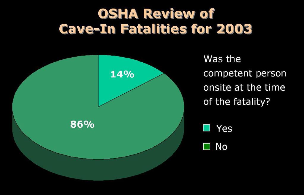
6
7 COMPOTENT PERSON Assigned by the employer Training/experience & knowledge soils use of protective systems requirements of subpart P ( ).

8 COMPOTENT PERSON (continued) Capable of detecting conditions leading to cave-ins failures in protective systems hazardous atmospheres other hazardous conditions including confined spaces.
9 What s the Last Piece of the Competent Person Pie? AUTHORITY to fix what is wrong!


10 Definition Excavation Any man-made cut, cavity, trench, or depression in earths surface, formed by earth removal


11 Definition Trench An excavation in which material removal forms a narrow opening in the ground. Unlike large excavations, a trench is generally deeper than it is wide. Width is not greater than 15 feet.
12 SOIL CLASSIFICATION Stable Rock: means natural solid mineral matter that can be excavated with vertical sides and remain intact while exposed. Type A: Cohesive soils with an unconfined, compressive strength of 1.5 ton per square foot (tsf) or greater. clay, silty clay, sandy clay, clay loam. Not Type A if: fissured, subject to heavy traffic, vibration or pile driving, previously disturbed (dug up) or sloped, layered system where the layers dip into the excavation on a slope of four horizontal to one vertical (4H:1V) or greater;

13 Type A Soil- Example (clay and cemented soils) Not Type A if: Fissured Subject to vibration Previously disturbed
14 SOIL CLASSIFICATION Type B" means: (i) Cohesive soil with an unconfined compressive strength greater than0.5 tsf but less than 1.5 tsf ; or (ii) Granular non-cohesive soils including: angular gravel (similar to crushed rock), silt, silt loam, sandy loam and, (iii) Previously disturbed soils except those which would otherwise be classed as Type C soil, (iv) Type A, but is fissured or subject to vibration; or (v) Dry rock that is not stable
15 SOIL CLASSIFICATION "Type C" means: (i) Cohesive soil with an unconfined compressive strength of 0.5 tsf (48 kpa) or less; or (ii) Granular soils including gravel, sand, and loamy sand; or (iii) Submerged soil or soil from which water is freely seeping; or (iv) Submerged rock that is not stable

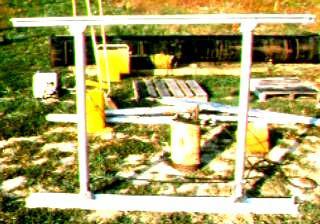
16 Soil Weight Example
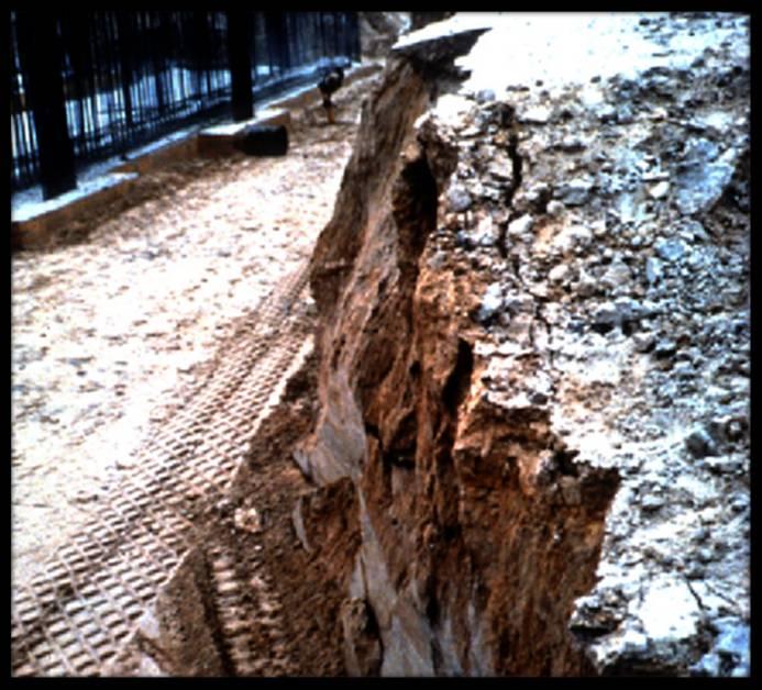
17 Collapse Forces Shear wall collapse speed 45 mph 1 cubic foot of soil can weigh from 100 to 125 lb.
18 Speed of Collapsing Dirt Imagine this coming down on top of you

19 Imagine if dirt can do this to a ladder..


20 Manual Soil Testing Procedures Thumb penetration Ribbon test Dry strength test Plasticity


21 Manual Soil Testing Procedures Penetrometer Shearvane
22

23 Underground Installations Can be among the largest unexpected costs to contractor

24 UNDERGROUND UTILITY LINE WORK All underground utility lines that may reasonable be expected to be encountered shall be determined prior to opening an excavation.
25 CALL 811 Call is routed to local One-Call Service center Tell operator where you will be digging and local utility companies will be notified Utility company will send a locator to mark approximate location of underground lines, pipes and cables. One-Call Service center will issue a ticket for work to be completed with start date and time. ND work must be completed in 10 days, varies from state to state Call to local One-Call Service center must be made business hours (depends upon state) prior to excavation work.

26 UTILITY LINE COLORS


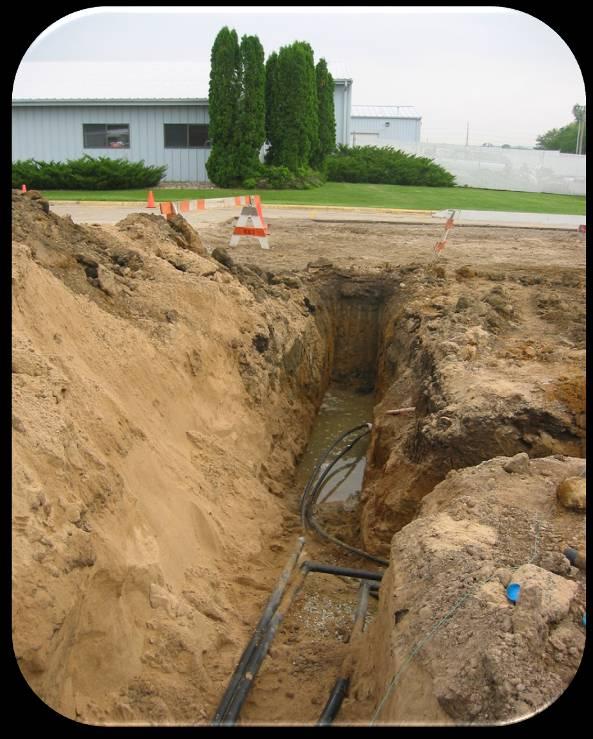
27 WORKING AROUND LINES Once utility lines are marked work may proceed. No mechanical equipment used within two feet of either side of marked utility line. Hand digging should be used within the two feet Zone of Danger

28 SUBSURFACE ENCUMRANCES All hazards to employees shall be removed or supported. Examples include: Retaining Walls Fencing Foundations

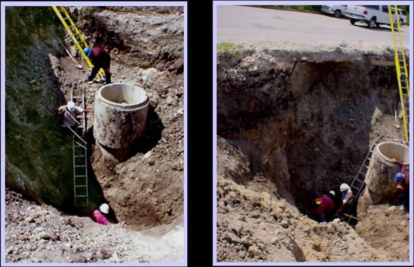
29 ACCESS/EGRESS A stairway, ladder, ramp or other safe means of egress shall be located in excavations deeper than 4 feet. No more than 25 feet of lateral travel to means of egress. Ladder must extend at least 3 feet above excavation.
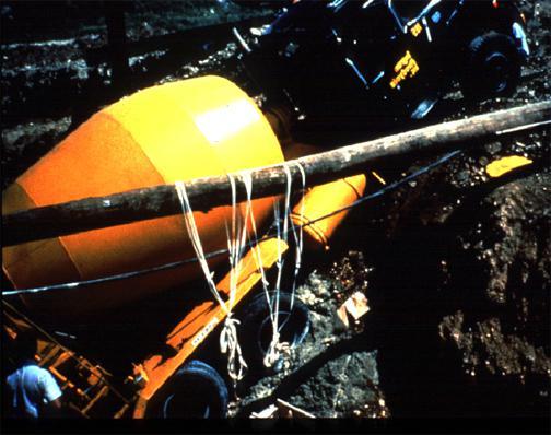
30 EXPOSURE TO FALLING LOADS No person shall be permitted underneath loads handled by lifting or digging equipment. Stay out of swing radius of equipment Use a line that is connected to the load to help guide and for control tag line Stand far away from materials being loaded and unloaded
31 HAZARDOUS ATMOSPHERE Testing must be done in excavations greater than 4 feet in depth What would be considered hazardous or toxic excavation atmosphere? Oxygen levels less than 19.5% and greater than 23.5%...why? Combustible gas levels Combustible gas levels Some trenches qualify as confined spaces..
32 WHEN IS TESTING REQUIRED? Before anyone enters a trench 4 ft or deeper Periodic testing to ensure conditions haven t changed
33 WATER ACCUMULATION Adequate precautions must be taken when water is accumulations is present: Support or Shield System Water Removal System Safety Harness and Lifeline

34 OSHA CITATION


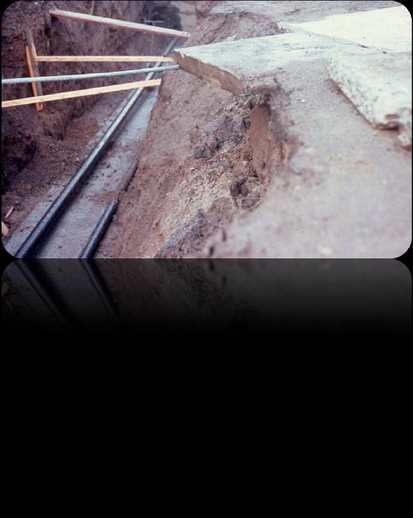
35 WATER or SEWER LINES SEVERED
36 WATER ACCUMULATION
37 Stability of Adjacent Structure Where stability of adjoining buildings, walls, sidewalks, pavements or other structures are endangered by excavation operations, support systems such as shoring, bracing, or underpinning shall be provided to ensure stability of such structures.

38 STABILITY OF ADJACENT STRUCTURES Support systems must be in place to protect employees to ensure stability of structure.
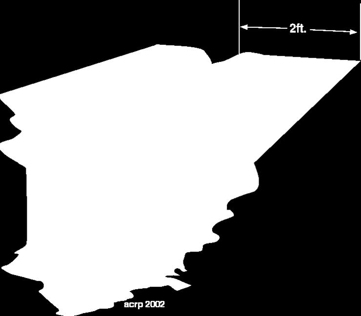
39 Protection of employees from loose rock or soil Spoil (dirt taken out of hole) banks shall be set back at least 2 ft. or more to ensure that no materials fall back into the excavation.
40 Temporary Spoil Spoil (dirt taken out of hole) should be placed so that it channels rainwater and other run-off water away from the excavation. Spoil should be placed so that it cannot accidentally run, slide, or fall back into the excavation. OSHA Office of Training and Education 40
41 INSPECTIONS Daily inspections of excavations, the adjacent areas, and protective systems shall be made by a competent person for evidence of a situation that could result in possible cave-ins, indications of failure of protective systems, hazardous atmospheres, or other hazardous conditions. An inspection shall be conducted by the competent person prior to the start of work and as needed throughout the shift. Inspections shall also be made after every rainstorm or other hazard increasing occurrence. These inspections are only required when employee exposure can be reasonably anticipated.

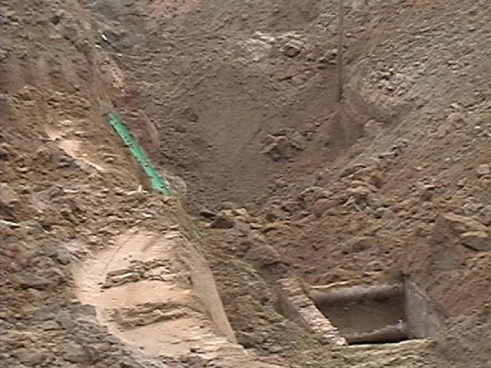
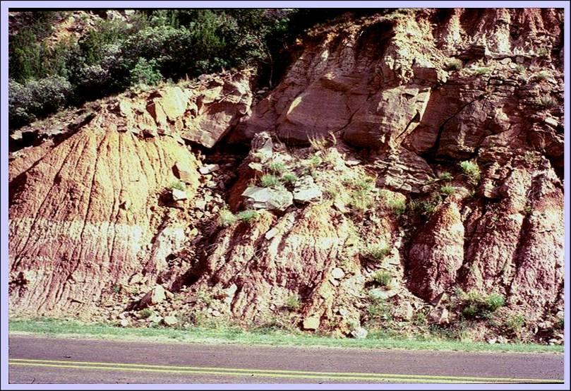
42 FISSURED SOIL

43 FISSURED SOIL

44 Protective systems may also be required in trenches less than 4 ft. if a significant collapse potential exists (a)(1)
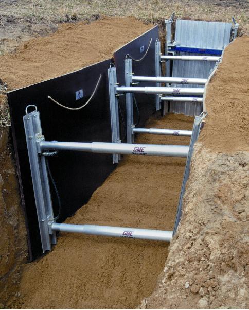
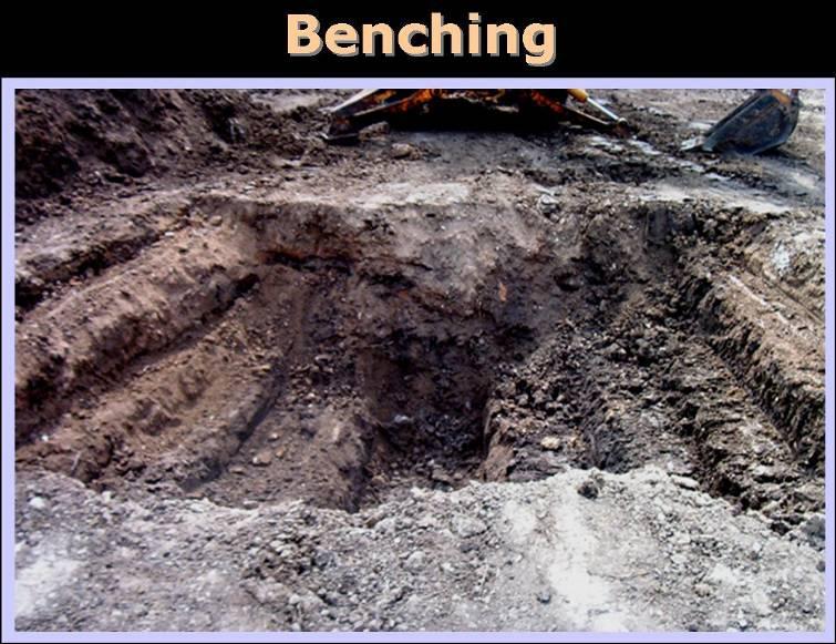
45 PROTECTIVE SYSTEMS Shield (shield system) -- a structure able to withstand a cave-in and protect employees with the structure. Shields can be permanent structure or can be designed to be portable and moved along as work progresses. Also known as trench box or trench shield. Shoring (shoring system) -- a structure such as a metal hydraulic, mechanical or timber shoring system that supports the sides of an excavation and which is designed to prevent cave-ins. Sloping (sloping system) -- protects employees from cave-ins by excavating to form sides of an excavation that are inclined away from the excavation to prevent cave-ins. The angle of incline varies with differences in such factors as the soil type, environmental conditions of exposure, and application of surcharge loads. Benching (Benching system) protects employees from cave-ins by excavating the sides of an excavation to form one or more of a series of horizontal levels or step.

46 Trench Shield / Trench Box Shields are manufactured by a number of companies and are designed to protect workers working within the confines of the shield. Top of Trench shield / box must be at least 18 inches above trench lip. Additionally, the shield must be designed by a Registered Professional Engineer, be in good condition, and used properly.

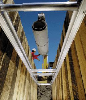
47 SHIELD SYSTEM Trench box, trench shield being lowered into hole

48 SHIELD SYSTEM Trench box or shield placed in hole


49 Shield system must extend at least 18 above toe of trench slope

50

51 OSHA VIDEO

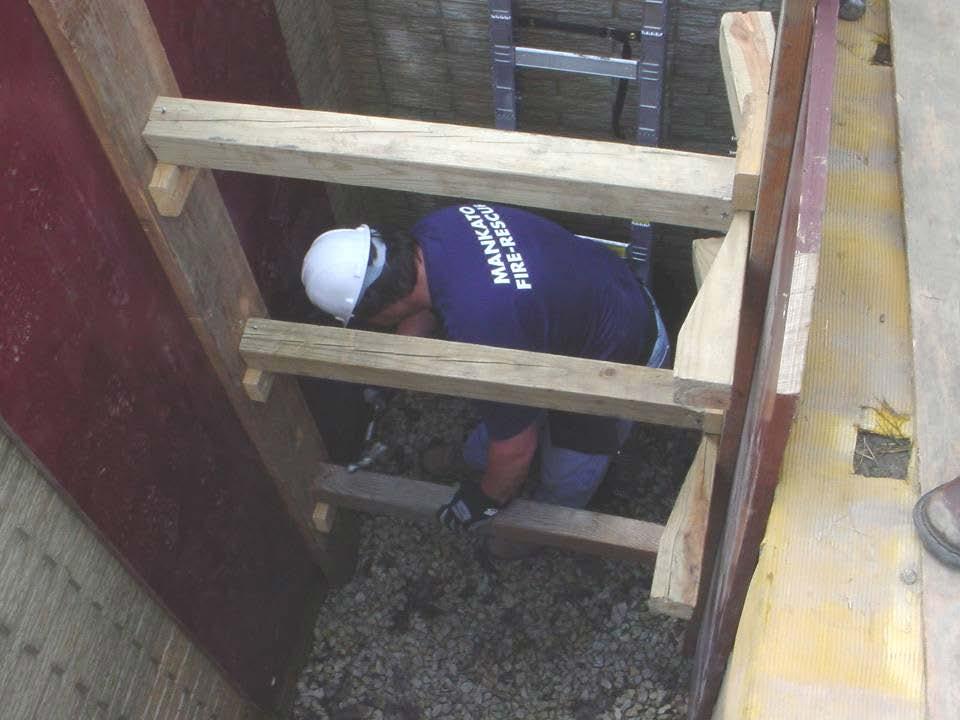
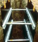
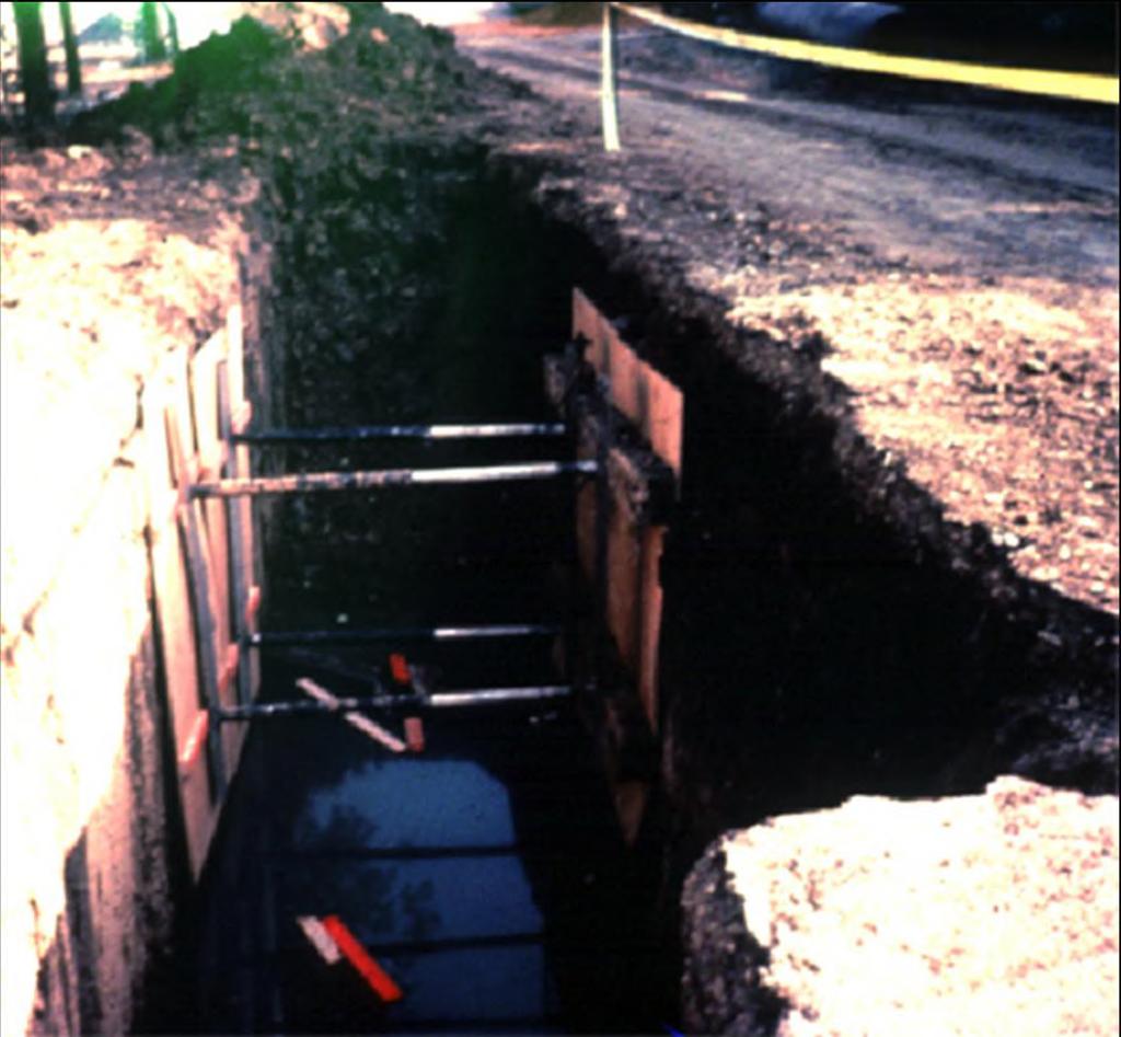
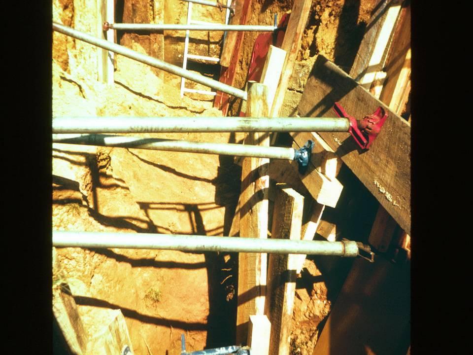
52 SHORING SYSTEMS
53 Shoring Concept Works by creating double funnel effect Strut pressurizes trench wall in all directions Strong enough to prevent soil from starting to move set in four feet intervals vertically and horizontally as a general rule.
54 SHORING SYSTEMS Protection provided by collapse prevention System must fit tight against trench walls Shoring materials and system design depend upon trench dimensions

55 SHORING OPTIONS A. Use Appendix C (Timber Shoring) or Appendix D ( Aluminum Shoring) B. Use shoring system manufacturer s tabulated data C. Use tabulated data tables approved by Registered Professional Engineer D. Use shoring system designed by RPE


56 Shores Timber Hydraulic Screw Jacks
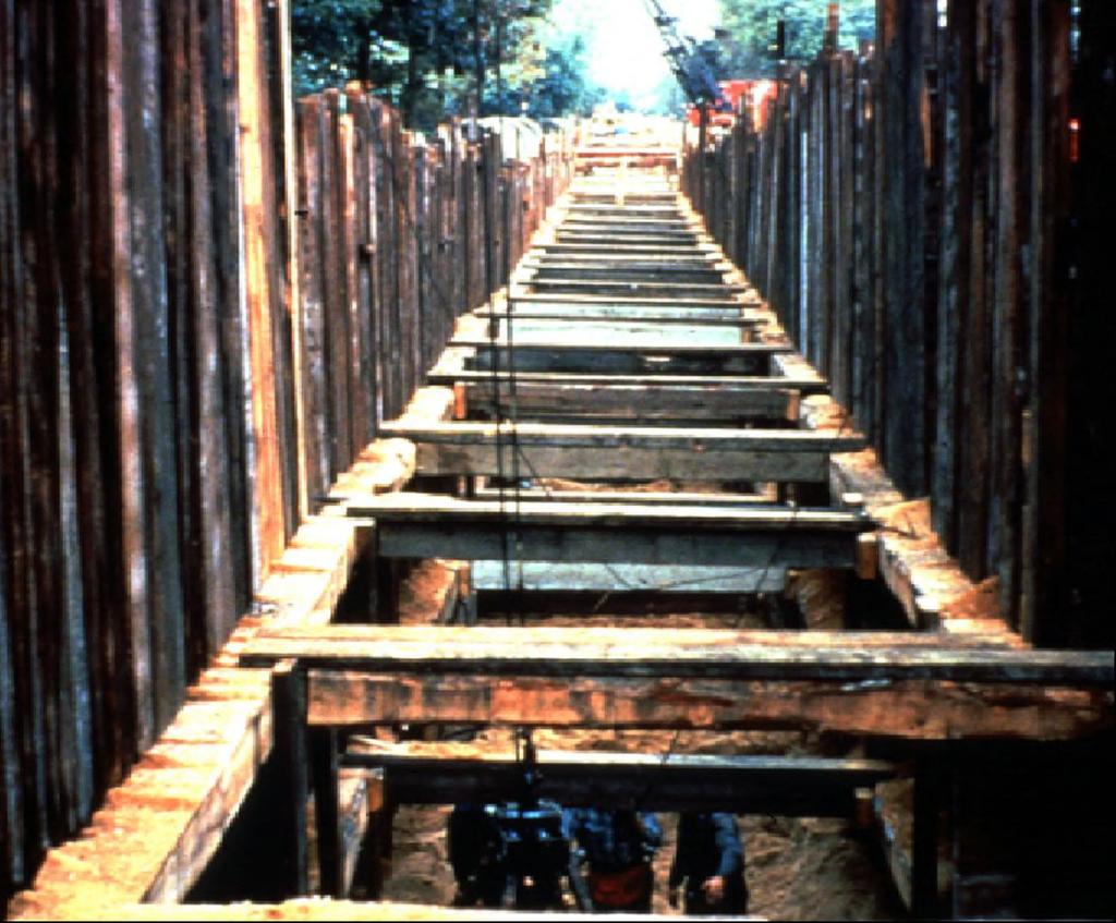
57 Timber Shoring
58 58

59 TIMBER SHORING Custom-built and very strong Commonly used in deep trenches Members must be loaded prior to earth movement

60 Appendix C - Timber Shoring Based on Douglas Fir or Oak timbers Timbers must be free of defects

61 TIMBER SHORING

62 TYPES OF SHEETING
63

64

65
66

67
68
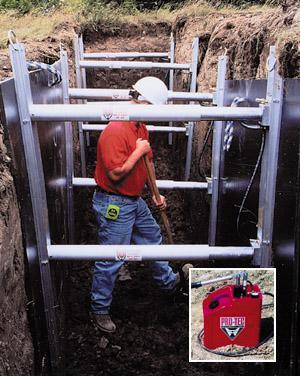
69 Aluminum Hydraulic Shoring


70 SHORING SYSTEMS
 configurations")
71 ALUMINUM SHORING Portable and quickly deployed May be used as a stand-alone system or as a temporary shore during assembly of timber shoring system APPENDIX D Tables given for both vertical and horizontal (waler) configurations

72 ALUMINUM SHORING VERTICAL HORIZONTAL
73 Cylinders


74 ALUMINUM SHORING DIMENSIONS

75 CAUTION! Ordinary ¾ plywood CANNOT be used as sheeting unless approved by an RPE If approved, it can only be used to control local raveling


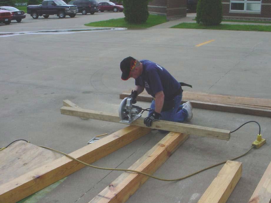
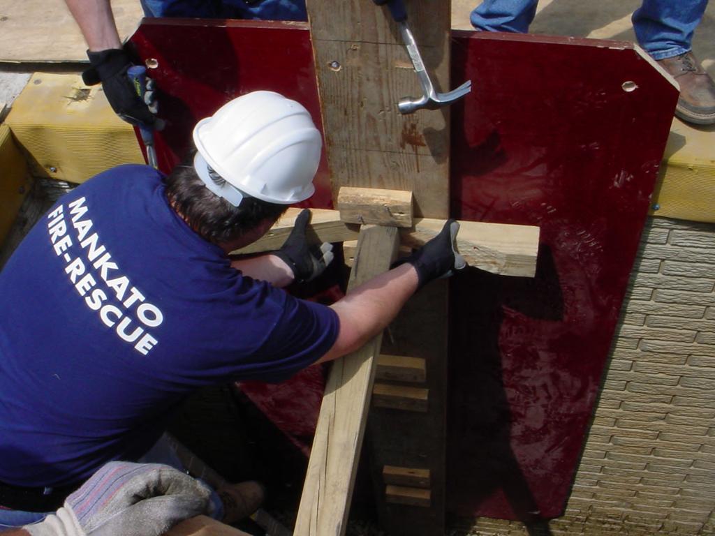
76 Finland Form or Inform Sheeting 4 x 8 home made panels Strongback 2 x 12 x 12 Panel rope used for lowering Manufactured panels (14-ply arctic white birch)
77 77


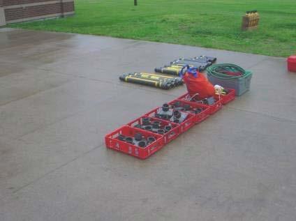
78 Pneumatic Shores Paratech Airshore
79 MATERIALS AND EQUIPMENT Equipment used for protective systems must not have damage or defects that impair function. If equipment is damaged, the competent person must examine it to see if it is suitable for continued use. If not suitable, remove it from service until a professional engineer approves it for use.
80 MAXIMUM ALLOWABLE SLOPES SOIL OR ROCK TYPE FOR EXCAVATIONS LESS THAN 20 FEET DEEP Stable Rock Vertical (90 Deg. ) Type A ¾:1 (53 Deg.) Type B 1:1 (45 Deg.) Type C 1 ½:1 (34 Deg.) Footnote - Sloping or benching for excavations greater than 20 feet deep shall be designed by a registered professional engineer.
81
82 SLOPING
83 SLOPING


84 BENCHING SYSTEMS ONLY TO BE USED ON TYPE A & B SOIL
85
86 UNSAFE ATTITUDES I Know what I m doing. It can t happen to me. I ve been doing it that way for years. I d sleep in that hole! Don t worry, we ll watch the walls and tell you if you need to get out.
87 SITE PLANNING Before beginning excavation: Evaluate soil conditions Construct protective systems Test for low oxygen, hazardous fumes and toxic gases Provide safe in and out access Contact utilities Determine the safety equipment needed

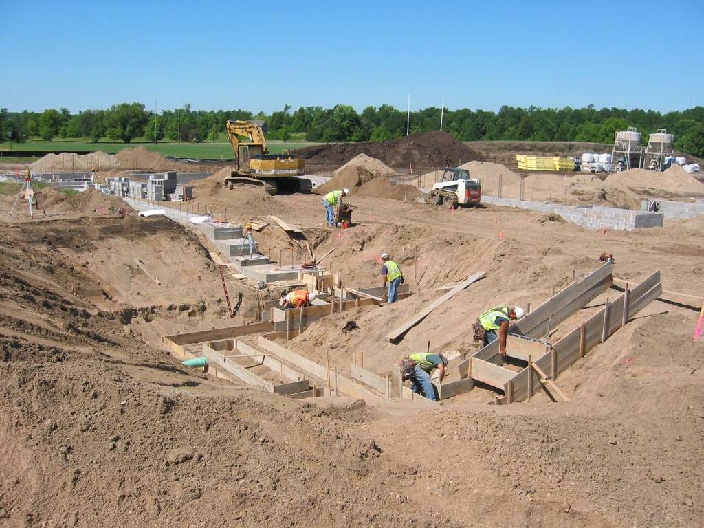
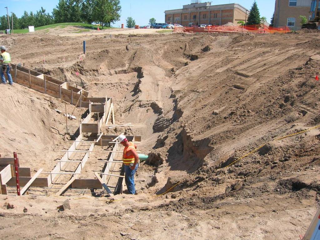
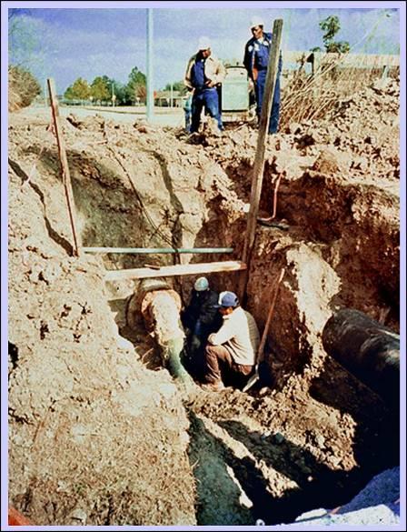
88 Hazards Present?
89 89

90
91


92

93
94

95
96
97

98
99
100