THE CHANGUINOLA DAM & HYDRO ELECTRICAL POWER PLANT
|
|
|
- Cecil Greene
- 5 years ago
- Views:
Transcription


1 THE CHANGUINOLA DAM & HYDRO ELECTRICAL POWER PLANT A large construction project with its own cement and fly ash import operation Ad Ligthart c2i Club des Carriers Industriels Indépendants

2 CONTENTS OF PRESENTATION The construction project Location Scope of supply The dam Design Roller compacted concrete The tunnel Design Method of construction The powerhouse and mini hydro Design Construction Bridges and roads Temporary facilities RCC batching plant RCC delivery system Aggregate mining area Crushing plant Aggregate storage area Power plant Workshop Small concrete plant Housing camps


3 CONTENTS OF PRESENTATION The cement and fly ash import operation Key factors Sourcing cement and fly ash Logistics Setting up the supply chain Shipping routes Planning the terminal facility Building a floating terminal Shipping Final preparations Operations
4 PROJECT INFORMATION LOCATION

")


5 Bocas del Toro Province Very poor province Over 60% Indigenous (Indian) population 50% of houses without water sanitation and electricity Life expectancy 57 years! Banana Economy BOCAS DEL TORO PROVINCE

6 PROJECT SITE
7 1. A large dam of mass concrete (1 million cubic meter) Height 100 meters Width at top 600 meters 2. Tunnel Length 4 km Diameter 10 meters 3. Powerhouse 2 Turbines Total 210 MW 4. Mini powerhouse at dam 9 MW with Eco flow km of permanent road 10 km of temporary road incl. bridges, drainage systems, hill improvements, etc. Total project value USD 400 million SCOPE OF SUPPLY

8 Dam Design Height of dam Width of dam (top) Concrete quantity 860,000 m m 615 m A mass concrete design was chosen over a rock and earth filled dam as this would shorten the construction period with one year.

9 Dam Design A curved dam design was chosen over a gravity type design as this saved about 15% of concrete. The concrete mix design and quality of construction had to be a significant higher levels because of this.
10 DAM CONSTRUCTION
11 DAM CONSTRUCTION
12 DAM CONSTRUCTION
13 DAM CONSTRUCTION
14 DAM CONSTRUCTION
15 DAM CONSTRUCTION
16 DAM CONSTRUCTION
17 DAM CONSTRUCTION
18 DAM CONSTRUCTION
19 DAM CONSTRUCTION
20 DAM CONSTRUCTION
21 DAM CONSTRUCTION
22 DAM CONSTRUCTION
23 DAM CONSTRUCTION
24 DAM CONSTRUCTION
25 DAM CONSTRUCTION
26 DAM CONSTRUCTION

27 DAM CONSTRUCTION
28 DAM CONSTRUCTION
29 DAM CONSTRUCTION
30 DAM CONSTRUCTION
31 DAM CONSTRUCTION


32 Mass concrete without rebar 14 months of 24/7 placing operations Heat of hydration key issue High fly ash ratio Substantial amounts of retarder used to extend workability during interruptions Delivery by tph delivery system Transported over dam with articulated dump trucks Spread out by bull dozers Compacted by vibrating rollers ROLLER COMPACTED CONCRETE
 outlet TUNNEL DESIGN")
33 Total tunnel length 4100 meters Diameter 10 meters At the end of the tunnel it had to go deeper to keep sufficient rock strength Extra adit (or surge) outlet TUNNEL DESIGN


34 Tunnel is blasted through the rock Tunnel is stiffened with rock dowels and shotcrete. This also prevents water leakage from the tunnel TUNNEL CONSTRUCTION
35 River at +55 masl Powerhouse acess level +67 masl POWERHOUSE DESIGN
36 Powerhouse Total output 205 mw 2 Turbines Total height of building 28 m Turbine height 16 m Largest part of building is located into the rock POWERHOUSE DESIGN
37 POWERHOUSE CONSTRUCTION
38 Powerhouse construction site POWERHOUSE CONSTRUCTION
39 Powerhouse construction site POWERHOUSE CONSTRUCTION


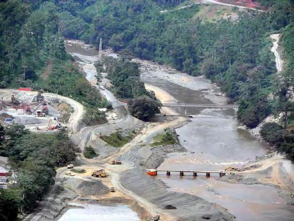
40 No bridge yet Temporary bridge Culvert construction ROADS AND BRIDGES Permanent bridge


41 ROADS AND BRIDGES Permanent roads 25 km Temporary roads 10 km 4 Bridges 8 Large culverts Substantial work on hillside stabilisation

42 Dam Tunnel Powerhouse Concrete plant (RCC) Capacity 650 m 3 /h tph delivery system tons of sand/aggregate storage tons of cement and flyash storage Aggregate mining area 3 km long along river 2,5 m tons required Crushing plant tons per week 5 qualities Aggregate storage area 1 million tons storage 8,000 kw power plant, diesel driven Large workshop Batching plant regular concrete Laboratories Safety organisation facilities Housing camps TEMPORARY FACILITIES

43 RCC plant 650 m 3 /hour capacity 4 Mixers Delivery system to dam 2000 tph RCC PLANT AND DELIVERY SYSTEM

44 A platform for the RCC plant was blasted out of the hill close to the dam RCC PLANT AND DELIVERY SYSTEM

45 A platform for the RCC plant was blasted out of the hill close to the dam RCC PLANT AND DELIVERY SYSTEM

46 RCC PLANT AND DELIVERY SYSTEM

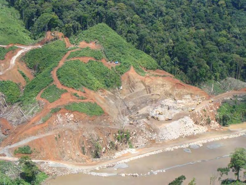
47 Aggregate mining Total two million tons of sand and aggregates required All taken from riverbed Sizes mm, mm, 10-5 mm, fines, natural sand Storage area of one million tons AGGREGATE MINING AREA

48 AGGREGATE MINING AREA

49 AGGREGATE STORAGE


50 Power Station 8000 kw Rebar workshop Wood workshop Health and safety offices Workshop Logistical warehouse OTHER TEMPORARY FACILITIES

51 HOUSING CAMPS

52 HOUSING CAMPS
53 Project Cement and fly ash supply April October 2007 Preparations October November 2007 Feasibility study October 2007 to mid 2009 Earth moving, road construction, surface preparation, plant construction Mid 2009 to end 2010 Construction of tunnel, powerhouse January March 2008 Concept terminal design and permit application December 2009 March 2011 Construction of dam March August 2008 March October 2008 Purchasing barge, terminal equipment, trucks, etc. Sourcing cement and fly ash May 2011 Closing diversion tunnels September 2008 September 2009 Project July 2009 October 2009 Cement and fly ash supply June 2011 Lake full January 2009 October 2009 Conversion floating terminal Construction shore silos and facilities Big Bag operations November 2009 February 2011 March 2011 July 2011 Bulk operations Demobilisation July September 2011 September 2011 April 2012 Start-up Demobilisation TIME FRAME


54 ARRANGING THE CEMENT AND FLY ASH SUPPLY FACTORS Quantities Overall quantity tons Ratio between cement and fly ash not yet known early in the project Cement type I/type II issue Usage fluctuations Project schedule still subject to change early in the project Regular concrete use spread unevenly over project RCC use during 16 months with fluctuations between tpm and tpm Maximum daily peak tons Infrastructure limitations Poor roads Small banana port without sufficient dock availability or storage area Supply sources and shipping routes not known early in project LOGISTICS
55 Fly ash supply No fly ash available in Central America Best possible supply from USA Cement supply Issues with suppliers in Panama Shortage situation Both companies in plant expansion situation Quality issues Cement supply situation in Caribbean not easy But. Economical crisis in USA cement available for export AVAILABILITY
 2,7 mtpa capacity 70.000 tons of finished product silos Type 1 II cement!")
56 Fly ash Separation Technologies (Titan America Group) Production unit tons per month at Big Bend Power plant, Apollo Beach tons product silo at plant Additional ton silo at Titan terminal in Tampa Cement Titan America Pennsuco plant (North of Miami) 2,7 mtpa capacity tons of finished product silos Type 1 II cement!! Shiploading in Port Everglades directly by bulk trucks from plant AVAILABILITY
57 FLOW SHEET SEABORNE CEMENT AND FLY ASH SUPPLY SYSTEM Key factor is shipping distance Shipping distance determines ship size Ship size determines required storage facilities in loading and discharge port and required loading and discharge capacities. Spreadsheet business model of complete supply system calculating full logistics and economics Basis is concrete placement schedule and from there the whole system is calculated backwards to cement and fly ash suppliers Calculates all logistical factors as well as operating and capital costs Calculation of many scenarios possible as well as different storage and equipment options

58 SETTING UP THE SUPPLY CHAIN SHIPPING ROUTES
 Project site SHIPPING")
59 Shipping route Trucking route (18 km) Project site SHIPPING ROUTES


60 PLANNING THE TERMINAL FACILITY

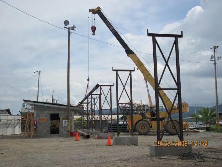
61 Floating terminal Lavioletta Storage capacity tons 5 Holds Length 151,3 m Width 22,9 m Depth 11,0 m Draft 8,6 m By means of two spudpoles the floating terminal can be fixed in position but move up and down with tide and cargo condition BUILDING A FLOATING TERMINAL


62 Conversion Work - Barge purchased in Canada and towed to Limon in Costa Rica - Repairs and modifications to hold structure - Product conveying pipelines, fuel, water and waste water pipelines - Refurbishment ballast system - New gantry for ship unloader - Installation of ship unloader - Installation of generator set - Installation of spud poles! - Electrical installation BUILDING A FLOATING TERMINAL
 Vessel characteristics Cargo capacity approx. 7.")

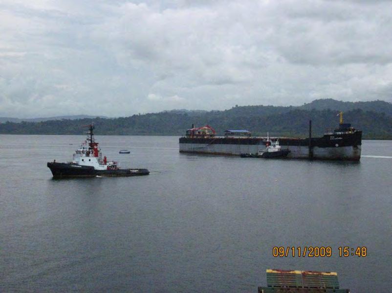
63 SHIPPING 2 Self discharging vessels taken in time charter One for the full concrete placement period (16 months) One for the peak placement period (9 months) Vessel characteristics Cargo capacity approx tons Loading time 48 hours Discharge time 30 hours Roundtrip time to Florida is 14 days (at reduced speed) Charter party agreement Based on BIMCO uniform time charter Additional conditions Loading and discharge conditions (must match with supplier and receiver agreements and capabilities) Vessel to comply with US regulations! Various issues regarding trading in Caribbean


64 SETTING UP THE SUPPLY CHAIN FINAL PREPARATIONS

65 OPERATIONS LOADING FLY ASH IN TAMPA

66 LOADING CEMENT IN PORT EVERGLADES

67 LEAVING TAMPA

68 SEAVOYAGE TO ALMIRANTE

69 ARRIVAL ALMIRANTE
70 ARRIVAL IN ALMIRANTE

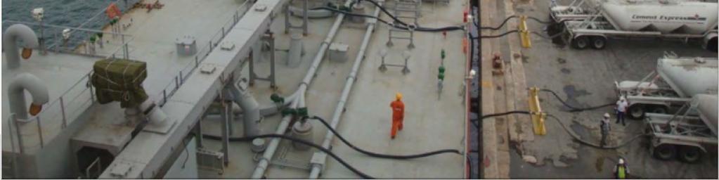
71 TERMINAL OPERATIONS
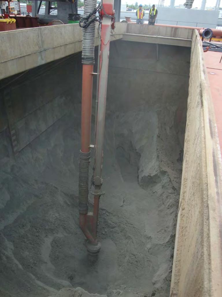
72 TERMINAL OPERATIONS

73 PUMPING CEMENT AND FLY ASH TO SHORE

74 FLOATING PIPELINE TO SILOS

75 TRUCK LOADING SILOS

76 TRUCKING TO PROJECT SITE

77 SILOS AT RCC PLANT

78 AND THE DAM GROWS

79 AND THE DAM GROWS

80 AND THE DAM GROWS

81 AND THE DAM GROWS

82 AND THE DAM GROWS
83 AND THE DAM GROWS

84 AND THE DAM GROWS

85 AND THE DAM IS READY

86 PROJECT COMPLETED

87 PROJECT COMPLETED
88 THANK YOU