Lightweight and Stable
|
|
|
- Marshall Copeland
- 5 years ago
- Views:
Transcription


1 Steel Stud & Track

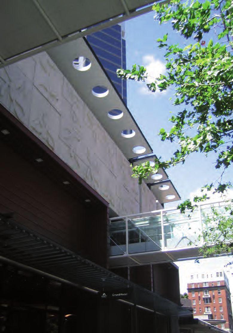
2 General Offices Apartments Hotels Retail Malls Hospitals Banks USG drywall steel stud and track systems offer practical and economical solutions for screw fixing plasterboard to internal, non-load bearing partitions, fire and acoustic rated walls, stairwells, bulkheads and corridor ceilings. Dimensionally stable, they stay straight and true, saving on time, materials and labour. They are strong, yet lightweight, easy to handle and require few tools Showrooms Education Industrial Fire rated areas For fire protection and safety, USG Steel Stud & Track System can provide a number of different Fire Resistant Ratings in combination with the appropriate plasterboard lining. Lightweight and Stable ISO 9000 Quality Assurance USG Interiors Pacific Ltd is an accredited ISO manufacturer Licence No Standards and Building Codes USG uses the following Standards in its manufacturing, testing and marketing policies for compliance with the Building Code of New Zealand AS/NZS Steel Sheet and Strip AS Fire Resistance of Elements of Building Construction AS/NZS Cold Formed Steel Structures Code AS/NZS Structural Design Actions NZBC B1/VM1 - NZ Building Code Verification Method B1/VM1 Clause 2 NZBC B2 Durability - USG Drywall Steel Stud & Track system will have a minimum serviceable life of 15 years when installed in a dry, non-corrosive, interior installation /w/ /p/ /e/ supplied by Quality ISO 9001 ISO 9001 AND ISO CERTIFIED

; FIPENZ (Structural); CPEng; IntPE (NZ), herby certify that maximum height tables prepared for USG non-loadbearing steel stud and track systems, comply with the requirements of: AS/ NZS 1170")

3 User s Guide ADVANTAGES of USG Steel Stud For all areas requiring a smoothly finished, monolithic wall plane Flat or curved Fire Resistant Ratings Flexibility of configuration Dimensionally stable Impervious to rot, fungal and insect attack Corrosion resistant Won t warp, twist or bow Easily worked, few tools required Non-combustible New Zealand made for New Zealand conditions Contents System Components Page 4 Standards References 5 Project Information 6 Wind Speed Table Selectors 7 Wall Height Tables 8-15 Certification I, Ernest B Lapish, MICE C. Eng. (London); FIPENZ (Structural); CPEng; IntPE (NZ), herby certify that maximum height tables prepared for USG non-loadbearing steel stud and track systems, comply with the requirements of: AS/ NZS 1170 Structural Design Actions, AS/NZS 4600:2005 Cold Form Steel Structures Code, and the New Zealand Building Code Testing and Calculations Physical testing was conducted at the Civil Materials Laboratory, Department of Civil and Resource Engineering, University of Auckland. Structural engineers Lapish Enteprises Ltd were engaged to calculate from the test results the maximum allowable wall heights, summarized in the tables on pages 8-15, based on the criteria outlined in this brochure. Managing Director Lapish Enteprises Ltd 3

 Stud 32mm Stud Depth X mm BMT 51 64 75 92 100 150 0.50 0.55 X 0.")
 mm long * 40mm leg for 150mm track # To order only Deflection Head Track Fire Track X Track Depth X mm BMT")
 mm long # To order only Nogging Track Track Depth X mm X Centres 51 64 75 92 100 150 30mm 300 N/A # # # # #")

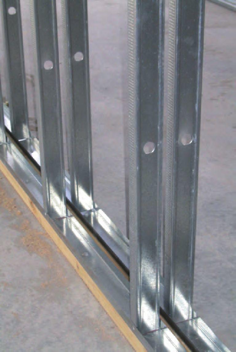
4 System Components USG Steel Stud and Track systems are manufactured in New Zealand using New Zealand Steel, in a variety of industry standard depths, lengths and gauges to suit the majority of interior partition system requirements. (Options not specifically listed may be able to be manufactured subject to engineering data and minimum order quantities.) Stud 32mm Stud Depth X mm BMT X mm Floor/Ceiling Track Track Depth X mm X BMT mm* (or 2500 #) mm long * 40mm leg for 150mm track # To order only Deflection Head Track Fire Track X Track Depth X mm BMT mm (or 2500 #) mm long # To order only Nogging Track Track Depth X mm X Centres mm 300 N/A # # # # # 400 N/A # # # # # 0.75 BMT 3600mm long 450 N/A # # # # # 600 N/A # # N/A Not available # To order only Features Six standard depths to cater for the majority of applications Knurled stud faces assist screw fixing by stopping slipping and damage to board. Knurling also gives a better bond when adhesive is used with screw fixing. 2700mm + Ø25mm coined service holes The USG branding ensures easy identification of genuine components for compliance 2400mm 300mm 1000mm 2000mm 2500mm 4
5 Standards References The following information is taken from the AS/NZS 1170, as a quick reference guideline to assist with the selection of correct tables to determine the most appropriate stud and track combination to comply with the requirements of AS/NZS Terrain Category AS/NZS , Category 3 Terrain with numerous closely spaced obstructions 3m to 5m high such as areas of suburban housing Category 4 Terrain with numerous large, high (10m to 30m high) and closely spaced obstructions such as large city centres and well-developed industrial complexes Building Importance Level AS/NZS , Table 3.2 Type 2: Normal structures not covered by Types 3 and 4; eg: single family dwellings, car parking buildings Type 3: Structures that may contain people in crowds, or contents of high value to the community or pose risks to people in crowds. eg: Where more than 300 people can congregate in one area Day care facilities with a capacity greater than 150 Primary or secondary school facilities with a capacity greater than 250 Colleges or adult education facilities with a capacity greater than 500 Healthcare facilities with a capacity of 50 or more resident patients but not having surgery or emergency treatment facilities Airport terminals, principal railway stations with a capacity greater than 250 Correctional institutions Multi-occupancy residential, commercial (including shops), industrial, office and retail buildings designed to accommodate more than 5000 people and with a gross area greater than 10,000 m² Public assembly buildings, theatres and cinemas of greater than 1000 m² Emergency medical and other emergency facilities not designated as post-disaster Power generating facilities, water treatment and waste water treatment facilities and other public utilities not designated as post disaster Buildings and facilities not designated as post disaster containing hazardous materials capable of causing hazardous conditions that do not extend beyond the property boundaries Type 4: Structures with special post-disaster functions eg: Buildings and facilities designated as essential facilities Buildings and facilities with special post-disaster function Medical emergency or surgical facilities Emergency service facilities such as fire, police stations and emergency vehicle garages Utilities or emergency supplies or installations required as backup for buildings and facilities of Importance Level 4 Designated emergency shelters, designated emergency centres and ancillary facilities Buildings and facilities containing hazardous materials capable of causing hazardous conditions that extend beyond the property boundaries 5

6 Project Information The following steps will guide you through to the correct height tables and provide a project summary. Step 1 Terrain Category Select the Terrain Category from descriptions on page 5, or from architectural specification. Terrain Category 3 Terrain Category 4 Step 2 Building Importance Level Step 3 Wind Region Select the Building Importance Level from descriptions on page 5, or from architectural specification. Type 2 Type 3 Type 4 Select the Wind Region from the map A6 A7 W KEY TO LOCATIONS 1 - Tauranga 2 - Huntly 3 - Hamilton 4 - Upper Hutt 5 - Blenheim 5 4 Step 4 Site Wind Speed Establish the Site Wind Speed from the local Territorial Authority if not already provided Low - 32mps Medium - 37mps High - 44mps Very High - 50mps 6
7 Site Wind Speeds Select the project Site Wind Speed Table and from the information on page 6 opposite then go to the appropriate Wall Height page as indicated within the tables. Low Wind Speed - 32mps Pages 8-9 Terrain Category 3 Terrain Category 4 Building Importance Level Building Importance Level Type 2 Type 3 Type 4 Type 2 Type 3 Type 4 Wind Region A6 / A7 W N/A N/A N/A N/A N/A Medium Wind Speed - 37mps Pages Terrain Category 3 Terrain Category 4 Building Importance Level Building Importance Level Type 2 Type 3 Type 4 Type 2 Type 3 Type 4 Wind Region A6 / A7 W N/A N/A N/A N/A N/A High Wind Speed - 44mps Pages Terrain Category 3 Terrain Category 4 Building Importance Level Building Importance Level Type 2 Type 3 Type 4 Type 2 Type 3 Type 4 Wind Region A6 / A7 W Very High Wind Speed - 50mps Pages Terrain Category 3 Terrain Category 4 Building Importance Level Building Importance Level Type 2 Type 3 Type 4 Type 2 Type 3 Type 4 Wind Region A6 / A7 N/A N/A N/A W N/A N/A N/A 7
8 Wall Height Tables Both Sides Low Wind Speed design wind pressure - 32mps Thickness Maximum Wall Height (metres) Maximum Wall Height (metres) x 400 ctrs 51 x 400 ctrs 64 x 600 ctrs 64 x 450 ctrs 75 x 450 ctrs x 450 ctrs 100 x 400 ctrs 100 x 300 ctrs 100 x 300 ctrs NOTES: Tables are based on standard plasterboard as a minimum. Specialist function boards (eg. Fire, acoustic etc) may be substituted Values are based on the same thickness boards each side. Increased thickness board on just one side or multiple layers may be substituted Stud depths and gauge are minimums. Deeper stud and/or thicker gauge may be substituted if required for other reasons Stud spacing is a maximum. Closer centres may be used if required for other reasons Other stud sizes and spacing not listed may be suitable contact USG for advice LOAD ON TRACK FIXINGS (kn) at 600mm centre fixing maximum Stud Height (metres) kn FASTENER TYPE AND QUANTITY FOR TRACK FIXINGS at 600mm centre fixing maximum (evenly space multiple fixings) Load (kn) Concrete Floor 3.8 x 32mm Ramset Timber Floor or Joist M6 Dynabolt x 22mm Ramset Pin (gas) Type 17 12g x 40mm Steel 10g-16 x waferhead screw mm Blind Rivet - Steel N/A N/A 3.2mm Blind Rivet - Aluminium N/A N/A N/A 8
9 Wall Height Tables One Side Only Low Wind Speed design wind pressure - 32mps Thickness x 400 ctrs 75 x 450 ctrs x 600 ctrs 100 x 600 ctrs 100 x 450 ctrs 100 x 300 ctrs 100 x 300 ctrs NOTES: Tables are based on standard plasterboard as a minimum. Specialist function boards (eg. Fire, acoustic etc) may be substituted Values are based on the same thickness boards each side. Increased thickness board on just one side or multiple layers may be substituted Stud depths and gauge are minimums. Deeper stud and/or thicker gauge may be substituted if required for other reasons Stud spacing is a maximum. Closer centres may be used if required for other reasons Other stud sizes and spacing not listed may be suitable contact USG for advice Continuous Nogging Track The USG Continuous Nogging Track is designed to be used to give support to and prevent twisting of the steel stud, particularly during installation of the plasterboard linings, single sided linings, and for taller wall heights. It may also be required where lighter weight articles are anticipated to be hung on the wall eg, picture, mirrors etc. It should be noted that if heavy articles are to be hung off the wall, this will require specific engineering design and correct installation prior to lining the wall. MINIMUM NUMBER OF CONTINUOUS NOGGING TRACKS Wall Height (metres) Both Sides One Side Nogging Track Positioning Position equally spaced over the height of the wall. For deflection head track walls unlined or lined one side only, secure an extra nogging track 100mm on centre below the head track 9
10 Wall Height Tables Both Sides Medium Wind Speed design wind pressure - 37mps Thickness x 400 ctrs 51 x 400 ctrs 64 x 450 ctrs 64 x 450 ctrs x 450 ctrs 75 x 400 ctrs 75 x 450 ctrs 92 x ctrs 92 x ctrs 92 x 0.55 boxed@ 400 ctrs 92 x ctrs 92 x ctrs 92 x ctrs 100 x ctrs NOTES: Tables are based on standard plasterboard as a minimum. Specialist function boards (eg. Fire, acoustic etc) may be substituted Values are based on the same thickness boards each side. Increased thickness board on just one side or multiple layers may be substituted Stud depths and gauge are minimums. Deeper stud and/or thicker gauge may be substituted if required for other reasons Stud spacing is a maximum. Closer centres may be used if required for other reasons Other stud sizes and spacing not listed may be suitable contact USG for advice LOAD ON TRACK FIXINGS (kn) at 600mm centre fixing maximum Stud Height (metres) kn FASTENER TYPE AND QUANTITY FOR TRACK FIXINGS at 600mm centre fixing maximum (evenly space multiple fixings) Load (kn) Concrete Floor 3.8 x 32mm Ramset Timber Floor or Joist M6 Dynabolt x 22mm Ramset Pin (gas) Type 17 12g x 40mm Steel 10g-16 x waferhead screw mm Blind Rivet - Steel N/A N/A 3.2mm Blind Rivet - Aluminium N/A N/A N/A 10
11 Wall Height Tables One Side Only Medium Wind Speed design wind pressure - 37mps Thickness x 450 ctrs 75 x 450 ctrs x 600 ctrs 92 x ctrs 100 x 450 ctrs 150 x 450 ctrs 100 x 600 ctrs 92 x ctrs 100 x ctrs 100 x 300 ctrs 150 x 450 ctrs 100 x 450 ctrs 92 x ctrs 92 x ctrs 100 x 300 ctrs 100x ctrs 150 x 450 ctrs NOTES: Tables are based on standard plasterboard as a minimum. Specialist function boards (eg. Fire, acoustic etc) may be substituted Values are based on the same thickness boards each side. Increased thickness board on just one side or multiple layers may be substituted Stud depths and gauge are minimums. Deeper stud and/or thicker gauge may be substituted if required for other reasons Stud spacing is a maximum. Closer centres may be used if required for other reasons Other stud sizes and spacing not listed may be suitable contact USG for advice Continuous Nogging Track The USG Continuous Nogging Track is designed to be used to give support to and prevent twisting of the steel stud, particularly during installation of the plasterboard linings, single sided linings, and for taller wall heights. It may also be required where lighter weight articles are anticipated to be hung on the wall eg, picture, mirrors etc. It should be noted that if heavy articles are to be hung off the wall, this will require specific engineering design and correct installation prior to lining the wall. MINIMUM NUMBER OF CONTINUOUS NOGGING TRACKS Wall Height (metres) Both Sides One Side Nogging Track Positioning Position equally spaced over the height of the wall. For deflection head track walls unlined or lined one side only, secure an extra nogging track 100mm on centre below the head track 11
12 Wall Height Tables Both Sides High Wind Speed design wind pressure - 44mps Thickness x 400 ctrs 51 x 400 ctrs 75 x 450 ctrs 75 x 400 ctrs x 300 ctrs 92 x ctrs 92 x ctrs 100 x 400 ctrs 92 x ctrs 150 x 450 ctrs 150 x 300 ctrs 150 x 300 ctrs 150 x 450 ctrs 150 x 300 ctrs 150 x 300 ctrs 150 x 450 ctrs 150 x 300 ctrs NOTES: Tables are based on standard plasterboard as a minimum. Specialist function boards (eg. Fire, acoustic etc) may be substituted Values are based on the same thickness boards each side. Increased thickness board on just one side or multiple layers may be substituted Stud depths and gauge are minimums. Deeper stud and/or thicker gauge may be substituted if required for other reasons Stud spacing is a maximum. Closer centres may be used if required for other reasons Other stud sizes and spacing not listed may be suitable contact USG for advice LOAD ON TRACK FIXINGS (kn) at 600mm centre fixing maximum Stud Height (metres) kn FASTENER TYPE AND QUANTITY FOR TRACK FIXINGS at 600mm centre fixing maximum (evenly space multiple fixings) Load (kn) Concrete Floor 3.8 x 32mm Ramset Timber Floor or Joist M6 Dynabolt x 22mm Ramset Pin (gas) Type 17 12g x 40mm Steel 10g-16 x waferhead screw mm Blind Rivet - Steel N/A N/A 3.2mm Blind Rivet - Aluminium N/A N/A N/A 12
13 Wall Height Tables One Side Only High Wind Speed design wind pressure - 44mps Thickness x 400 ctrs 75 x 450 ctrs 92 x 400 ctrs 92 x 400 ctrs 92 x 400 ctrs x ctrs 92 x ctrs 92 x ctrs 92 x ctrs 92 x ctrs 150 x 400 ctrs 150 x 300 ctrs 150 x 400 ctrs 150 x 300 ctrs 150 x 400 ctrs 150 x 300 ctrs NOTES: Tables are based on standard plasterboard as a minimum. Specialist function boards (eg. Fire, acoustic etc) may be substituted Values are based on the same thickness boards each side. Increased thickness board on just one side or multiple layers may be substituted Stud depths and gauge are minimums. Deeper stud and/or thicker gauge may be substituted if required for other reasons Stud spacing is a maximum. Closer centres may be used if required for other reasons Other stud sizes and spacing not listed may be suitable contact USG for advice Continuous Nogging Track The USG Continuous Nogging Track is designed to be used to give support to and prevent twisting of the steel stud, particularly during installation of the plasterboard linings, single sided linings, and for taller wall heights. It may also be required where lighter weight articles are anticipated to be hung on the wall eg, picture, mirrors etc. It should be noted that if heavy articles are to be hung off the wall, this will require specific engineering design and correct installation prior to lining the wall. MINIMUM NUMBER OF CONTINUOUS NOGGING TRACKS Wall Height (metres) Both Sides One Side N/A Nogging Track Positioning Position equally spaced over the height of the wall. For deflection head track walls unlined or lined one side only, secure an extra nogging track 100mm on centre below the head track 13
14 Wall Height Tables Both Sides Very High Wind Speed design wind pressure - 50mps Thickness x 600 ctrs 64 x 400 ctrs 75 x 400 ctrs x 300 ctrs 92 x ctrs 92 x ctrs 100 x 400 ctrs 92 x ctrs 150 x 450 ctrs 150 x 300 ctrs 150 x 300 ctrs 150 x 450 ctrs 150 x 300 ctrs 150 x 300 ctrs 150 x 450 ctrs 150 x 300 ctrs NOTES: Tables are based on standard plasterboard as a minimum. Specialist function boards (eg. Fire, acoustic etc) may be substituted Values are based on the same thickness boards each side. Increased thickness board on just one side or multiple layers may be substituted Stud depths and gauge are minimums. Deeper stud and/or thicker gauge may be substituted if required for other reasons Stud spacing is a maximum. Closer centres may be used if required for other reasons Other stud sizes and spacing not listed may be suitable contact USG for advice LOAD ON TRACK FIXINGS (kn) at 600mm centre fixing maximum Stud Height (metres) kn FASTENER TYPE AND QUANTITY FOR TRACK FIXINGS at 600mm centre fixing maximum (evenly space multiple fixings) Load (kn) Concrete Floor 3.8 x 32mm Ramset Timber Floor or Joist M6 Dynabolt x 22mm Ramset Pin (gas) Type 17 12g x 40mm Steel 10g-16 x waferhead screw mm Blind Rivet - Steel N/A N/A 3.2mm Blind Rivet - Aluminium N/A N/A N/A 14
15 Wall Height Tables One Side Only Very High Wind Speed design wind pressure - 50mps Thickness x 450 ctrs 92 x 400 ctrs 92 x 400 ctrs 100 x 450 ctrs x ctrs 92 x ctrs 92 x ctrs 100 x ctrs 92 x ctrs 92x ctrs 100 x ctrs 100 x ctrs 150 x 400 ctrs 150 x 300 ctrs 150 x 400 ctrs 150 x 300 ctrs 150 x 450 ctrs 150 x 300 ctrs NOTES: Tables are based on standard plasterboard as a minimum. Specialist function boards (eg. Fire, acoustic etc) may be substituted Values are based on the same thickness boards each side. Increased thickness board on just one side or multiple layers may be substituted Stud depths and gauge are minimums. Deeper stud and/or thicker gauge may be substituted if required for other reasons Stud spacing is a maximum. Closer centres may be used if required for other reasons Other stud sizes and spacing not listed may be suitable contact USG for advice Continuous Nogging Track The USG Continuous Nogging Track is designed to be used to give support to and prevent twisting of the steel stud, particularly during installation of the plasterboard linings, single sided linings, and for taller wall heights. It may also be required where lighter weight articles are anticipated to be hung on the wall eg, picture, mirrors etc. It should be noted that if heavy articles are to be hung off the wall, this will require specific engineering design and correct installation prior to lining the wall. MINIMUM NUMBER OF CONTINUOUS NOGGING TRACKS Wall Height (metres) Both Sides One Side N/A Nogging Track Positioning Position equally spaced over the height of the wall. For deflection head track walls unlined or lined one side only, secure an extra nogging track 100mm on centre below the head track 15


16 supplied by /w/ /p/ /e/ ISO 9001 AND ISO CERTIFIED