Submittal Information
|
|
|
- Stanley Wood
- 5 years ago
- Views:
Transcription

1

2 AQUAPEX Tubing Coil Lengths Project Information th Street West Apple Valley, MN Phone: Submittal Information Fax: Submittal Information Component Job Name: Location: Engineer: Contractor: Mfg Rep: Part No. Ordered: Quantity Ordered: P.O. Number: Date Submitted: Submitted By: Approved By: Technical Data Material PEX-a (Engel Method) Standard Grade Hydrostatic Ratings 200 o 80 psi 180 o 100 psi (1/2" AQUAPEX only) 120 o 130 psi 73.4 o 160 psi Linear Expansion Rate 1.1 in/10 o F/100 ft Product Information and Application Use AB Wirsbo AQUAPEX tubing is for hot and cold potable water distribution systems. AQUAPEX is available for use in hydronic heating systems employing non-ferrous components. Ordering Information Dimensional Information Shipping Description Part Number A B C D E Weight [ ] 1/4" AQUAPEX, 100 ft coil F " 0.375" N/A N/A N/A 4 lbs [ ] 3/8" AQUAPEX, 400 ft coil F " 0.500" N/A N/A N/A 20 lbs [ ] 3/8" AQUAPEX, 1,000 ft coil F " 0.500" N/A N/A N/A 44 lbs [ ] 1/2" AQUAPEX, 100 ft coil F " 0.625" N/A N/A N/A 6 lbs [ ] 1/2" AQUAPEX, 300 ft coil F " 0.625" N/A N/A N/A 19 lbs [ ] 1/2" AQUAPEX, 1,000 ft coil F " 0.625" N/A N/A N/A 58 lbs [ ] 5/8" AQUAPEX, 300 ft coil F " 0.750" N/A N/A N/A 27 lbs [ ] 5/8" AQUAPEX, 1,000 ft coil F " 0.750" N/A N/A N/A 84 lbs [ ] 3/4" AQUAPEX, 100 ft coil F " 0.875" N/A N/A N/A 11 lbs [ ] 3/4" AQUAPEX, 300 ft coil F " 0.875" N/A N/A N/A 34 lbs [ ] 3/4" AQUAPEX, 500 ft coil F " 0.875" N/A N/A N/A 55 lbs [ ] 1" AQUAPEX, 100 ft coil F " 1.125" N/A N/A N/A 21 lbs [ ] 1" AQUAPEX, 300 ft coil F " 1.125" N/A N/A N/A 58 lbs [ ] 1" AQUAPEX, 500 ft coil F " 1.125" N/A N/A N/A 94 lbs [ ] 1 1/4" AQUAPEX, 100 ft coil F " 1.375" N/A N/A N/A 35 lbs [ ] 1 1/4" AQUAPEX, 300 ft coil F " 1.375" N/A N/A N/A 106 lbs [ ] 1 1/2" AQUAPEX, 100 ft coil F " 1.625" N/A N/A N/A 44 lbs [ ] 1 1/2" AQUAPEX, 300 ft coil F " 1.625" N/A N/A N/A 133 lbs Code Approvals/Standards ANSI/NSF 14 and 61 certified ASTM F876 ASTM F877 ASTM F1960 CAN/CSA B137.5 ICBO ER 5142 IPC UPC NSPC UL 1821 (1/2" AQUAPEX) SBCCI (PST and ESI Report No. 9661) Installation Refer to the Wirsbo AQUAPEX Installation Handbook for more information. Refer to the Wirsbo Radiant Floor Installation Handbook for more information. Related Applications AQUAPEX Hot and Cold Potable Water AQUASAFE Fire Protection Systems Wirsbo Radiant Floor Heating Wirsbo Snow & Ice Melting Wirsbo Turf Conditioning 2002 Uponor Wirsbo AQUAPEX Tubing Submittal November 1, 2002
3 Rocky Mountain Colby Pipe Company of 1 6/11/2009 2:00 PM SUBMITTAL SPECIFICATION DATA SHEET 1. PRODUCT NAME Acrylonitrile Bultadiene Styrene (ABS) Plastic Pipe and Fittings for Drainage, Waste and Vent Systems 2. PRODUCT DESCRIPTION Basic Use: Sanitary drainage, waste, and vent systems and storm drainage systems. ABS pipe can be used in residential, commercial and industrial applications. Pipe and fittings are joined by solvent cementing. There is a full complement of ABS drainage pattern fittings available for DWV applications. Pipe and fittings are available in size 1 ¼ inch through 6 inches in diameter. Composition and Materials: ABS is a thermoplastic material made with virgin ABS compounds meeting the ASTM requirements of Cell Classification (pipe) and (fittings). Pipe is available in both solid wall and cellular core all. These can be used interchangeably. Grades: ABS pipe is identified as Schedule 40 pipe. This indicates the wall thickness of the pipe. The pipe can also be installed above or below grade. Limitations: ABS pipe is intended to be used in any conventional sanitary drainage or storm drainage system. Pipe is resistant to certain chemicals, however, specific analysis must be performed before pipe is considered for any special waste system. Contact the pipe manufacturer for a detailed list of chemicals that can be satisfactorily discharged through ABS pipe. Plastics are affected by ultraviolet (U/V) radiation. Pigments are added to the ABS to make pipe and fittings resistant to degradation. Pipe and fittings may be exposed to sunlight during construction, however, prolonged exposure is not advised. ABS pipe and fittings can withstand the normal temperatures encountered in a sanitary and storm drainage system. Recommended maximum temperature for continuous drainage applications is 180 F. 3. TECHNICAL DATA Applicable Standards: ABS Cellular Core DWV conforms to ASTM F-628. Quality Control: Pipe and fittings are listed and inspected by a third party. They conform to National Sanitation Foundation Standard NSF 14, IAPMO - Uniform Plumbing Code and the Canadian Standards Association. Fire Protection: ABS pipe and fittings are combustible materials, however, they may be installed in noncombustible buildings. In all cases the model building codes have determined that ABS must be protected at penetrations of walls, floors, ceilings, and fire resistance rated assemblies. The method of protecting the pipe penetration is by a through penetration protection assembly that has been tested and rated in accordance with ASTM E814. This assembly must have been tested and given an "F" rating. The "F" rating must be a minimum of the hourly rating of the fire resistance rated assembly that the ABS plastic pipe penetrates. Verify local code interpretations related to through penetrations with the jurisdiction having authority. Plumbing Codes: ABS pipe is permitted to be used in any sanitary drainage, waste, and vent system and storm drainage system without limitation, in the following model plumbing codes: BOCA National Plumbing Code, NAPHCC National Standard Plumbing Code and SBCCI Standard Plumbing Code. ABS plastic pipe is limited to being installed in buildings three stories above grade or less in height by the IAPMO Uniform Plumbing Code. Verify acceptance and installation of ABS piping systems with local code enforcement authorities having jurisdiction. USA Sizes & Packaging ABS SCHEDULE 40 DRAIN, WASTE, AND VENT PIPE WITH A CELLULAR CORE ASTM F-628 Listed with NSF and IAPMO Nominal Pipe Size Average O.D. Average Wall Average Length Lift Size Pieces per Lift 1.25" 1.660" 0.140" 20' N/A N/A 1.50" 1.900" 0.145" 20' 5,180' " 2.375" 0.154" 20' 3,340' " 3.500" 0.216" 20' 1,500' " 4.500" 0.237" 20' 960' " 6.625" 0.280" 20' N/A N/A APPROVAL Schedule 40 drain waste and vent pipe shall be Rocky Mountain Colby Pipe Company ABS DWV Cellular Core manufactured to ASTM F-628 and certified by a recognized listing agency. INFORMATION: Contact the Sales Office at (619) , or to sales@rmcp.com.

4
5

6

7

8
9
10
11
12
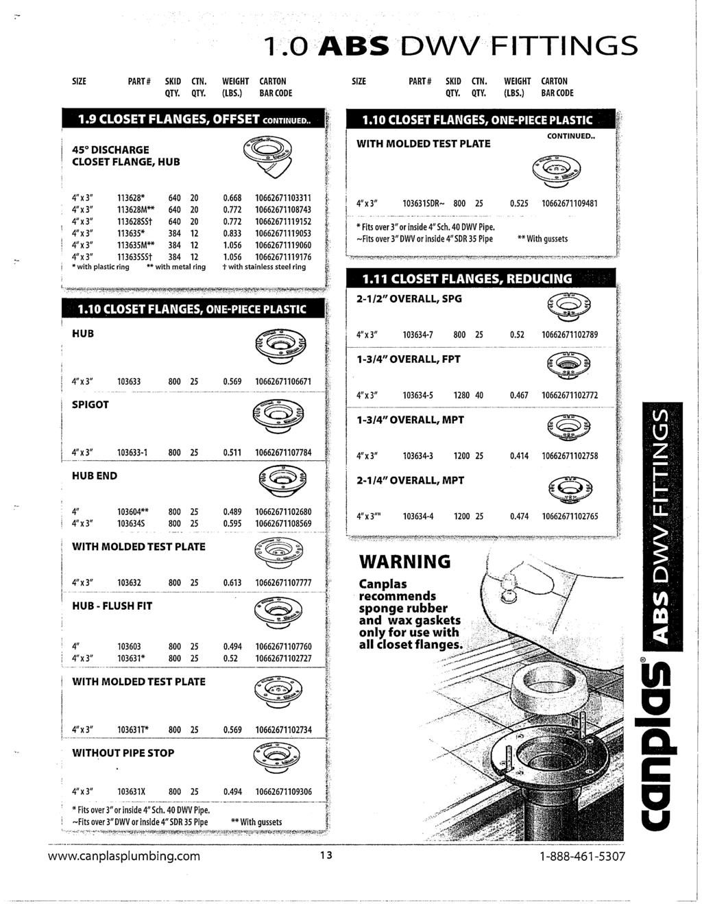
13

14
15

16
17
18
19
20
21
22
23 SPECIFIED TECHNOLOGIES INC. THE FIRESTOPPING SPECIALISTS # UL SYSTEM DESCRIPTION PRODUCT(S) 1 FC1010 Max. 4" steel, iron, or copper pipe, copper tube, LCI Intumescent Sealant conduit, or EMT. Caulk only. 2 WL1344 Max 4" steel, iron, or copper pipe, copper tube, conduit, LCI Intumescent Sealant or EMT. 0 to 1/8" annulus. 1/2" continuous caulk bead. Caulk only. GENERAL CERTIFICATE OF COMPLIANCE PRODUCT DATA SHEETS 1 LCI Intumescent Sealant MATERIAL SAFETY DATA SHEETS 1 LCI Intumescent Sealant IMPORTANT NOTICE: This submittal is comprised of user selected documents that have been assembled using an automatic printing and archiving system. Use of the products or designs referenced herein are at the sole discretion of the installer, specifier, or other designated project decision maker. Specified Technologies Inc (STI) makes no guarantees nor recommendations regarding the applicability of the products or designs contained in this document to the referenced project.
24 Ì94FC0Ç**ÈAAÇ!")tÎ F Ratings - 1 and 2 Hr (See Item 1) T Ratings - 1/2, 3/4, 1 and 1-1/2 Hr (See Item 2) L Rating At Ambient - Less Than 1 CFM/sq ft L Rating At 400 F - Less Than 1 CFM/sq ft A 1B 1A A 1D Section A-A 2 1. Floor-Ceiling Assembly - The 1 hr fire-rated solid or trussed lumber joist floor-ceiling assembly shall be constructed of the materials and in the manner specified in the individual L500 Series Floor-Ceiling Designs in the UL Fire Resistance Directory. The 2 hr fire-rated wood joist floor-ceiling assembly shall be constructed of the materials and in the manner specified in Design Nos. L505, L511 or L536 in the UL Fire Resistance Directory. The F Rating of the firestop system is equal to the hourly fire rating of the floor-ceiling assembly. The general construction features of the floor-ceiling assembly are summarized below: A. Flooring System - Lumber or plywood subfloor with finish floor of lumber, plywood or Floor Topping Mixture* as specified in the individual Floor-Ceiling Design. Max diam of floor opening is 5 in. B. Wood Joists* - For 1 hr fire-rated floor-ceiling assemblies, nom 10 in. deep (or deeper) lumber, steel or combination lumber and steel joists, trusses or Structural Wood Members* with bridging as required and with ends firestopped. For 2 hr fire-rated floor-ceiling assemblies, nom 2 by 10 in. lumber joists spaced 16 in. OC with nom 1 by 3 in. lumber bridging and with ends firestopped. C. Furring Channels - (Not Shown) - In 2 hr fire-rated assemblies, resilient galv steel furring installed perpendicular to wood joists between first and second layers of gypsum board (Item 1D). Furring channels spaced max 24 in. OC. In 1 hr fire-rated assemblies, resilient galv steel furring installed perpendicular to wood joists between gypsum board and wood joists as specified in the individual Floor-Ceiling Design. Furring channels spaced max 24 in. OC. D. Gypsum Board* - Nom 4 ft wide by 5/8 in. thick as specified in the individual Floor-Ceiling Design. First layer of gypsum board secured to wood joists or furring channels as specified in the individual Floor-Ceiling Design. Second layer of gypsum board (2 hr fire-rated assembly) screw-attached to furring channels as specified in the individual Floor-Ceiling Design. Max diam of ceiling opening is 5 in. Reproduced courtesy of Underwriters Laboratories, Inc. Created or Revised: January 2, 2009 (800) (908) FAX (908) techserv@stifirestop.com Website: R F-C-1010 PAGE 1 OF 2
25 2. Through Penetrants - One metallic pipe, conduit or tube installed approximately midway between wood joists. Diam of openings hole-sawed through flooring system and through gypsum board ceiling to be nom 1/2 in. greater than the outside diam of through-penetrant. For 1 hr rated floor assemblies, through penetrant to be installed either concentrically or eccentrically within the opening with an annular space of 0 in. (point contact) to 1/2 in. For 2 hr rated floor assemblies, through penetrant to be centered in the opening. Pipe, conduit or tube to be rigidly supported on both sides of floor-ceiling assembly. The following types and sizes of metallic pipes, conduits or tubing may be used: A. Steel Pipe - Nom 4 in. diam (or smaller) Schedule 5 (or heavier) steel pipe. B. Iron Pipe - Nom 4 in. diam (or smaller) cast or ductile iron pipe. C. Conduit - Nom 4 in. diam (or smaller) steel electrical metallic tubing or steel conduit. D. Copper Pipe - Nom 4 in. diam (or smaller) Regular (or heavier) copper pipe. E. Copper Tubing - Nom 4 in. diam (or smaller) Type L (or heavier) copper tubing. The T Rating of the firestop system is dependent upon the hourly rating of the floor-ceiling assembly and type of through-penetrant used as shown in the table below: Floor Ceiling Rating Hr Type of Penetrant Steel or Iron Pipe Steel Conduit Copper Tube or Pipe Steel or Iron Pipe Steel Conduit Copper Tube or Pipe T Rating Hr 1 1 3/4 1-1/2 1-1/2 1/2 3. Fill, Void or Cavity Material* - Sealant - Fill material forced into annulus to fill space to max extent possible on top surface of floor and bottom surface of ceiling. Min 3/8 in. diam bead of fill material applied at point contact location on top surface of floor and on bottom surface of gypsum board ceiling. SPECIFIED TECHNOLOGIES INC - SpecSeal Series SSS Sealant or SpecSeal LCI Sealant *Bearing the UL Classification Mark Reproduced courtesy of Underwriters Laboratories, Inc. Created or Revised: January 2, 2009 (800) (908) FAX (908) techserv@stifirestop.com Website: R F-C-1010 PAGE 2 OF 2
26 F Ratings - 1 and 2 Hr (See Item 1) T Rating - 1/4 Hr L Ratings At Ambient - Less Than 1 CFM/sq ft L Ratings At 400 F - Less Than 1 CFM/sq ft Ì83WL0Ç-LÈAAÇ!")QÎ A 1B A 3 Section A-A 1A 1. Wall Assembly -- The 1 or 2 hr fire rated gypsum board/stud wall assembly shall be constructed of the materials and in the manner specified in the individual U300 or U400 Series Wall and Partition Designs in the UL Fire Resistance Directory and shall include the following construction features: A. Studs -- Wall framing may consist of either wood studs or steel channel studs. Wood studs to consist of nom 2 by 4 in. (51 by 102 mm) lumber spaced max 16 in. (406 mm) OC. Steel studs to be min 3-1/2 in. (89 mm) wide and spaced max 24 in. (610 mm) OC. B. Gypsum Board* -- Thickness, type, number of layers and fasteners as required in the individual Wall and Partition Design. Max diam of opening is 5 in. (127 mm). The hourly F Rating of the firestop system is equal to the hourly fire rating of the wall assembly in which it is installed. 2. Through Penetrants -- One metallic pipe, conduit or tubing installed either concentrically or eccentrically within the firestop system. The annular space between pipe, conduit or tubing and periphery of opening shall be min of 0 in. (0 mm, point contact) to max 1/8 in. (3.2 mm). Pipe, conduit or tubing to be rigidly supported on both sides of wall assembly. The following types and sizes of metallic pipes, conduits or tubing may be used: A. Copper Tubing -- Nom 4 in. (102 mm) diam (or smaller) Type M (or heavier) copper tubing. B. Copper Pipe -- Nom 4 in. (102 mm) diam (or smaller) Regular (or heavier) copper pipe. C. Steel Pipe -- Nom 4 in. (102 mm) diam (or smaller) Schedule 5 (or heavier) steel pipe. D. Conduit -- Nom 4 in. (102 mm) diam (or smaller) steel electrical metallic tubing or rigid steel conduit. E. Iron Pipe -- Nom 4 in. (102 mm) diam (or smaller) cast or ductile iron pipe. 3. Fill, Void or Cavity Materials* - Sealant or Putty -- Min 1/2 in. (13 mm) diameter bead of sealant or putty applied continuously around the penetrant on the wall surfaces on both sides of the wall. SPECIFIED TECHNOLOGIES INC -- SpecSeal Putty, SpecSeal Series SSS Sealant, SpecSeal LCI Sealant *Bearing the UL Classification Mark Reproduced courtesy of Underwriters Laboratories, Inc. Created or Revised: January 2, 2009 (800) (908) FAX (908) techserv@stifirestop.com Website: R W-L-1344 PAGE 1 OF 1
27 Specified Technologies Inc. 200 Evans Way, Suite 2 Somerville, N.J Phone: (908) Fax: (908) Toll Free: (800) GENERAL CERTIFICATE of CONFORMANCE Description: SpecSeal Firestop Products Included Products: Series SSS Intumescent Sealant Series LCI Intumescent Sealant Series LC Latex Endothermic Sealant Series SSP Intumescent Putty Series EP Power Shield Box Insert Series SSWRED Intumescent Wrap Strips Series SSWBLU Intumescent Wrap Strips Series SSC Intumescent Firestop Collars Series LCC Intumescent Firestop Collars Series SSB Intumescent Firestop Pillows Series AS100 Elastomeric Spray Series AS200 Elastomeric Spray Series ES100 Elastomeric Sealant Series SSM Firestop Mortar Pensil Series PEN200 Silicone Foam Pensil Series PEN300 Silicone Sealant Pensil Series PEN300SL Silicone Sealant These products are tested to the following standards where applicable: ASTM STANDARD: E 814 E 119 E 1966 E 84 E 1399 Fire Tests of Through-Penetration Fire Stops Fire Tests of Building Construction and Materials Fire-Resistive Joint Systems Surface Burning Characteristics of Building Materials Cyclic Movement and Measuring the Minimum and Maximum Joint Widths of Architectural Joint Systems UL STANDARD 1479 Fire Tests of Through-Penetration Firestops 263 Fire Tests of Building Construction and Materials 2079 Tests for Fire-Resistance of Building Joint Systems 723 Tests for Surface Burning Characteristics of Building Materials Chemical Content Statements: No asbestos, PCB s or water-soluble intumescent ingredients are used or contained in these products. February1, 2002 James P. Stahl, Jr. Technical Manager Date
28 FBC System Compatible indicates that this product has been tested, and is monitored on an ongoing basis, to assure its chemical compatibility FlowGuard Gold, BlazeMaster and Corzan are licensed trademarks of The Lubrizol Corporation. FILL, VOID OR CAVITY MATERIALS FOR USE IN JOINT SYSTEMS AND THROUGH-PENETRATION FIRESTOP SYSTEMS. SEE UL DIRECTORY OF PRODUCTS CERTIFIED FOR CANADA AND UL FIRE RESISTANCE DIRECTORY. 3L73 1
29 UL System No. C-AJ-1353 UL System No. W-J-1098 UL System No. C-AJ UL System No. W-L-3169 UL System No. W-L-2241
30 UL System No. F-C-1074 UL System No. F-C-5043 UL System No. W-L-1222 UL System Nos. W-L-5121, W-L-5122 UL System No. W-L
31 4
32 Material Safety Data Sheet 4-JUN-2010 SpecSeal SERIES LCI SEALANT CHEMICAL PRODUCT/COMPANY IDENTIFICATION PRODUCT NAME...SpecSeal LCI Sealant CHEMICAL FAMILY...Mixture MANUFACTURER/DISTRIBUTOR Somerville, NJ PHONE NUMBERS HAZARDS IDENTIFICATION *************************************************** COMPOSITION/INFORMATION ON INGREDIENTS INGREDIENT NAME CAS NUMBER ALUMINA TRIHYDRATE GRAPHITE CALCIUM CARBONATE Page 1 of 3 MSDS - SpecSeal SERIES LCI Sealant FOD-5137
33 FIRST AID MEASURES FIRE FIGHTING MEASURES EXTINGUISHING MEDIA ACCIDENTAL RELEASE MEASURES HANDLING AND STORAGE EXPOSURE CONTROLS/PERSONAL PROTECTION None.... PEL(OSHA) TLV(ACGIH) PHYSICAL AND CHEMICAL PROPERTIES PHYSICAL FORM... SPECIFIC GRAVITY PERCENT VOLATILES EVAPORATION RATE... >1 BOILING POINT STABILITY AND REACTIVITY... CONDITIONS TO AVOID TOXICOLOGICAL INFORMATION Page 2 of 3 MSDS - SpecSeal SERIES LCI Sealant FOD-5137
34 ECOLOGICAL INFORMATION DISPOSAL CONSIDERATIONS TRANSPORTATION INFORMATION REGULATORY INFORMATION OTHER INFORMATION NPCA-HMIS Rating STATE RIGHT-TO-KNOW LAWS Alumina, Somerville, NJ Page 3 of 3 MSDS - SpecSeal SERIES LCI Sealant FOD-5137
35
36
37
38
39