Table of Contents Big expertise. Real convenience. Concrete commitment.
|
|
|
- Naomi Peters
- 5 years ago
- Views:
Transcription
1 Table of Contents General Shoring Safety Rules As Recommended By The Scaffolding, Shoring And Forming Institute... 1 General Guidelines... 1 Single And Independent Post Shore System Safety Rules As Recommended By The Scaffolding, Shoring And Forming Institute... 2 General Shoring Notes...3 Stability And Lateral Force Consideration On Shoring Systems... 4 Basic Equipment...5 Key Accessories...8 Pro-Shore Erection Sequence...9 Pro-Shore Perimeter Guardrail Attachment Procedures...11 Pro-Shore Panel Erection Sequence...12 Pro-Shore Stripping Sequence...13 Pro-Shore Panel Stripping Sequence...14 Pro-Shore Typical Application Details...15 Pro-Shore Panel Typical Application Details...21 Sloped Slabs...25 Bracing Slider...26 Minimum & Maximum Shore Heights... 27
2 GENERAL SHORING SAFETY RULES AS RECOMMENDED BY THE SCAFFOLDING, SHORING AND FORMING INSTITUTE It shall be the responsibility of all employers and users to read and comply with the following common sense guidelines which are designed to promote safety in the erection, dismantling and use of the shoring systems. These guidelines are not all inclusive nor do they supplant or replace other additional safety and precautionary measures to cover usual or unusual conditions. If these guidelines conflict in any way with any state, provincial, local or federal statute or governmental regulation, said statute or regulation shall supersede these guidelines and it shall be the responsibility of each employee and user to comply therewith and also to be knowledgeable and understand all state, local or federal statutes or governmental regulations. This pertains to Frame Shoring, Flying Deck Forms, Single Post Shoring, and Independent Post Shore Systems. GENERAL GUIDELINES 1. POST THESE SHORING SAFETY GUIDELINES in a conspicuous place and be sure that all persons who erect, dismantle or use shoring are aware of them. 2. FOLLOW ALL STATE, PROVINCIAL, LOCAL AND FEDERAL CODES, ORDINANCES AND REGULA- TIONS pertaining to shoring. 3. SURVEY THE JOB SITE. A survey by a qualified person shall be made of the job site for hazards, such as un-tamped earth fills, ditches, debris, high tension wires, unguarded openings and other hazardous conditions. These conditions should be corrected or avoided as noted in the following sections. 4. PLAN SHORING ERECTION SEQUENCE in advance and obtain necessary access equipment to accomplish the work safely. 5. INSPECT ALL EQUIPMENT BEFORE USING. Never use any equipment that is structurally defective in any way. Mark it or tag it as defective, then remove it from the job site. 6. A SHORING DRAWING prepared by a person qualified to analyze the loading intended and consistent with the manufacturer s recommended safe working loads, shall be used on the job at all times. 7. ERECT, DISMANTLE OR ALTER SHORING only under the supervision of a qualified person. 8. DO NOT ABUSE OR MISUSE THE SHORING EQUIP- MENT. 9. INSPECT ERECTED SHORING: (a) immediately prior to concrete placement; (b) during concrete placement and while vibrating concrete; and (c) after concrete placement until concrete is set. 10. NEVER TAKE CHANCES! IF IN DOUBT REGARDING THE SAFETY OR USE OF THE SHORING, CONSULT YOUR SHORING SUPPLIER. 11. USE SHORING EQUIPMENT only for the purposes or in ways for which it was intended. Use proper tools when installing equipment. 12. ERECTING AND DISMANTLING OF SHORING requires good physical condition. Do not work on shoring if you feel dizzy, unsteady in any way or are impaired in any way by drugs or any other substances. 13. DO NOT USE SHORING SYSTEMS for fall protection. 14. USE SUPPLIER / MANUFACTURER RECOMMEND- ED SAFE WORKING LOADS consistent with the deck panel configurations and height of posts used. 15. DO NOT MAKE UNAUTHORIZED CHANGES TO THE LAYOUT. Always consult the designer prior to making changes. 16. IF MOTORIZED CONCRETE EQUIPMENT is to be used, be sure that the shoring layout has been designed for use with this equipment and to ensure that lateral loads, vibration and other forces have been considered and adequate precautions have been taken to assure stability and such fact is noted on the layout. 17. USE SPECIAL PRECAUTIONS when shoring from or to sloped surfaces. 18. SAFE ACCESS SHALL BE PROVIDED TO ALL FORMWORK as required by applicable code. 1
3 19. PANELS EXPOSED TO UPLIFTING WIND FORCES SHALL BE LOCKED OR TIED DOWN to prevent panel uplift. 20. PROVIDE AND MAINTAIN A SOLID FOOTING to distribute maximum loads properly. 21. WIND LOAD: Erector must analyze the forming / shoring system for additional loads imposed from wind loading and provide adequate anchorage to resist these forces, including uplifting wind forces. 22. RESHORING is one of the most critical operations in formwork; consequently, the reshoring procedure shall be designed by a qualified person and should be approved by the architect I engineer of record. 23. DO NOT RELEASE FORMS until proper authority is given. SINGLE AND INDEPENDENT POST SHORE SYSTEM SAFETY RULES AS RECOMMENDED BY THE SCAFFOLDING, SHORING AND FORMING INSTITUTE A. ALL INDEPENDENT POST SHORE SYSTEM DECKS SHALL BE LATERALLY STABILIZED by the existing building structure and/or longitudinal, transverse, and diagonal bracing. Bracing shall be installed as the shores are being erected. B. FOLLOW SUPPLIER/MANUFACTURER S RECOM- MENDED DIRECTION if applicable for: Location and selection of deck panel type and stringers. Type and height of vertical shoring components. Starting points of deck layouts. C. PRIOR TO WORKING ON DECKS All posts shall be plumb in two directions and adjusted evenly to ensure proper bearing contact. Check plumb of post shores just prior to pour. Deck shall be laterally stabilized. D. FALL PROTECTION SHALL BE PROVIDED ON ALL OPEN SIDES AND OPENINGS in formwork and slabs as required by applicable code. E. PLAN DECK PANEL LAYOUT TO ENSURE AGAINST INSTABILITY AND UNSUPPORTED CANTILEVERS. Take all necessary precautions to avoid uplift of cantilevered panels during and after construction. Make certain that form panels intended to be cantilevered are tied down to prevent tipping. F. PANELS EXPOSED TO UPLIFTING WIND FORCES SHALL BE LOCKED OR TIED DOWN TO PREVENT PANEL UPLIFT. G. PLAN CONCRETE PLACEMENT METHODS AND SEQUENCES TO ENSURE BALANCED LOADING of shoring equipment and panels, including cantilevered panels. H. BRACING SHALL BE FASTENED SECURELY. Check to see that clamps, screws, pins and all other components are in a closed or engaged position. I. ALL VERTICAL AND HORIZONTAL SHORING should be installed and used in compliance with safety rules and recommendations published by The Scaffolding, 2
4 Shoring and Forming Institute. Erect Ledgers, LVLs and Panels from below. Never erect components while standing on previously erected deck. J. DO NOT INTERMINGLE DAYTON SUPERIOR supplied components with those of other suppliers. K. LATERAL BRACING FOR SINGLE POST SHORES in job-built filler areas must be designed and installed by contractor. L. CONTRACTOR TO PROVIDE SOLID WEDGING under all post shores bearing on or supporting a sloping slab. M. ENSURE THAT ALL LVL JOISTS AND PRO-SHORE PANELS are properly in the ledger grooves. N. WHEN CANTILEVERING LEDGERS, LVL JOISTS OR PRO-SHORE PANELS secure opposite end cantilevered component to prevent tipping. O. CHECK ALL LOAD PINS FOR FULL BEARING AND SECURE EACH load pin with cotter pin. P. PRO-SHORE DECKS ARE NOT INTENDED TO BE USED as a scaffold work platform. Q. DO NOT USE PRO-SHORE POSTS MORE THAN ONE TIER HIGH. Where greater shore heights are required, consult the Dayton Superior Engineering Department. R. PRO-SHORE POSTS WILL REQUIRE ADDITIONAL BRACING when shoring or bearing on sloping slabs. Contact the Dayton Superior Engineering Department for guidance with the bracing requirements. S. DRAWINGS ARE ILLUSTRATIVE ONLY. Specification of products and equipment shown herein are subject to change without notice. GENERAL SHORING NOTES 1. Contractor to check and verify all dimensions at job before proceeding with work. 2. Deviation from these layouts may be made only under the direction and supervision of a qualified person who by possession of a recognized degree, certificate, or professional standing, or who by extensive knowledge, training, and experience has successfully demonstrated the ability to solve or resolve problems relating to the subject matter, the work, or the project and/or with the consultation of Dayton Superior Corporation. 3. The shoring installation must comply with safe practice and with the requirements of governmental regulations, codes and ordinances. 4. Contractor shall design and provide suitable sills to properly distribute the imposed shoring loads. 5. When setting elevations, allow for compression of lumber and soil. 6. The design and construct ion of lumber in job-built filler areas, and formwork, is the responsibility of the contractor. 7. The formwork system must be stabilized to poured columns and walls. The layout as shown is designed with the provision that the framework system is restrained from lateral movement with respect to shoring. The contractor shall provide sufficient lateral support as necessary. 8. The shoring layout is not designed for motorized concrete placing equipment unless specifically stated. 9. The reshoring and backshoring procedures are the responsibility of others, and should be approved by the architect/engineer of record. 10. All vertical and horizontal shoring should be installed and used in compliance with safety rules and recommendations published by The Scaffolding, Shoring & Forming Institute, Inc. and those of Dayton Superior Corporation. Erect ledgers, LVLs and panels from below. Never erect components while standing on previously erected deck. 11. Do not intermingle Dayton Superior Corporation supplied components with those of other suppliers. 3
5 12. Lateral bracing for single post shores in job-built filler areas must be designed and installed by a contractor. 13. Allvertical shoring equipment shall be plumb in two directions unless otherwise specified on the shoring drawings. 14. Contractor to provide solid wedging under all post shores bearing on or supporting a sloping slab. 15. Follow all additional information shown on General Note Sheet and typical sheets of the shoring layout drawings. In the event a layout drawing is not available or job site conditions change contact Dayton Superior s Engineering Department. 16. Insure that all LVL Joists and Pro-Shore Panels are seated properly in ledger groves. 17. When cantilevering ledgers, LVL Joints or Pro- Shore Panels secure opposite end of cantilevered component to prevent tipping. 18. Check all load pins for full bearing and secure each load pin with a cotter pin. 19. Prior to pouring concrete, check all star nuts to assure they are tight and snug against bearing plates. 20. Pro-Shore panels are not intended to be used as a scaffold work platform. 21. Do not use Pro-Shore posts more than one tier high. Where greater shore heights are required, consult Dayton Superior s Engineering Department. 22. Pro-Shore posts will require additional bracing when shoring or bearing on sloping slabs. Contact the Dayton Superior Engineering Department for guidance with the bracing requirements. 23. Drawings are illustrative only. Specification of products and equipment shown herein are subject to change without notice. 24. Report any damaged Pro-Shore equipment to Dayton Superior for further instructions. This may include but is not limited to J-catches, panel siderails, Drop Heads, etc. STABILITY AND LATERAL FORCE CONSIDERATION ON SHORING SYSTEMS Stability Bracing is required during the erection and dismantling of the shoring system when it is freestanding without blocking to a permanent structure. The Pro-Shore Cross-Braces shown on the shoring drawings illustrate a typical method used for stability bracing. The Cross-Braces acting in conjunction with the Ledger and LVL connections at the top of the post shores provide additional stability in the longitudinal and traverse directions. In addition to the standard Pro- Shore Cross-Bracing, all shoring heights in excess of 305mm may require added bracing. Lateral Bracing is required to resist the horizontal forces acting on the shoring system, such as wind loads, concrete pressures against bulkheads or sloping soffits and dynamic loads during concrete placement. Blocking the plywood and components of the shoring system to the permanent structure provides lateral bracing. The cross-braces used as stability bracing may also provide lateral bracing when it is not possible to provide blocking to the structure. A qualified person should analyze every shoring system to determine what lateral bracing is required. Contact Dayton Superior Engineering for assistance. TYPICAL APPLICATION 4
6 BASIC EQUIPMENT Post Shores The selection of shores in the Pro-Shore system offers the largest range of heights in the industry: 2.0m to 6.4m. The single posts allow for a clean, unbraced area for material movement and easy access. All posts have eight (8) locations for Jet-Lok attachment. This expands the adaptability of the system when Cross-Braces are required to produce 4-legged towers for safe erection of the system. No tripods or wood bracing is required. The Posts have a 3.0:1 Factor of Safety while supplying safe support for slabs up to 475mm in depth. P/C Description Weight F57073 Primary Post 26 kg F m Extension 6.8 kg F57075 #3 Post Shore 19.5 kg Universal Drophead The Universal Drophead is a key component of the Pro- Shore System. The Drop Head facilitates the stripping process, allowing the LVLs (or Panels), Ledgers, and plywood to be stripped and moved forward to the next pour while maintaining a shore in place for structural support. Notes: P/C Description Weight F57079 Universal Drophead 6.8 kg F mm x 102mm Bolt 0.5 kg Add 51mm to minimum dimension for stripping Only use (1) 0.6m Extension per shore Ensure all load pins are secures with cotter pins (split pins) Refer to table on back page for minimum and maximum shoring heights using the Drophead 5
7 Ledgers Ledgers are utilized as the main stringers of the Pro- Shore System. They span from one Drophead to the next. The end catch at each end of the aluminum Ledger sets and locks into the catch plate on the Dropheads of adjacent shores. The Ledgers also have a catch on both sides which runs the length of the Ledger to receive Joists or Pro-Deck Panels. The profile on the bottom of the Ledgers allows accessories to be attached for different support applications. Pro-Shore Ledgers are color-coded and match colors on Dayton Superior Engineered drawings for ease of use and assembly on the job site. P/C Description Actual Length Weight F m Ledger - Red 1.7m 19 kg F m Ledger - Green 2.3m 25 kg F m Ledger - Silver 2.9m 31 kg Joists with End Catches LVLs and aluminum are used for the joists of the Pro- Shore System. They are lightweight and span from Ledger to Ledger. The end catch at each end of the joist sets and locks into the catch plate of parallel Ledgers. Since Ledgers have catch plates running their full lengths, joists can be placed at virtually any spacing to accommodate different slab thicknesses or job site conditions. Contractor-supplied plywood is placed on top of the LVL or aluminum joists. Pro-Shore joists are color-coded and match colors on Dayton Superior Engineered drawings. P/C Description Actual Length Weight F m LVL Joist - Black 1.1m 7.0 kg F LVL Joist - Blue 1.4m 7.0 kg F m LVL Joist - Red 1.7m 9.0 kg F m Alum. Joist - Orange 1.7m 9.0 kg 6
8 Cross-Bracing The Cross-Braces with the Pro-Shore System provide stability to safely begin the erection sequence. They are also used in cantilever conditions, adding stability to the local shores. Pro-Shore Cross-Braces are color-coded and match colors on Dayton Superior engineered drawings for ease of use and assembly on the job site. P/C Description C/C Dimension Weight F m x 2.4m Cross-Brace 2.4m 5.4kg F m x 2.4m Cross-Brace kg F m x 1.5m Cross-Brace kg F m x 1.2m Cross-Brace kg Panels Pro-Deck utilizes two standard, modular panel sizes. These panels are a powder-coated 108mm deep frame with a 13mm thick plywood deck pre-cut and placed inside the frame. P/C Description Weight F m x 1.8m Panel 20.9kg F m x 1.8m Panel Wood Replacement 8.2kg F m x 1.8m Panel 28.6kg 7
9 KEY ACCESSORIES Clips The Pro-Shore system can incorporate a set of different clips to safely and efficiently accommodate various job site specific applications P/C Description Weight F57068 Ledger to Drophead Clip.2kg F57069 Ledger to Hold Down Clip.2kg F57070 Ledger to Ledger Clip.2kg Guardrail Post w/twistlock P/C F kg The Guardrail Post can be attached to Ledgers and offers a safe connection for contractor-supplied safety railing. It is connected to Ledgers using a Twistlock. The Toeboard Support also features adjustability to slide up or down to accommodate different deck material. Bracing Slider w/ Two Jet-Loks P/C F kg The Bracing Slider is used to facilitate the use of Cross-Bracing in sloped slab conditions. It is attached at Jet-Lok locations of adjacent post shores. Ledger Hanger P/C F kg Ledger Hangers can be used to hang a Ledger below the main grid Ledgers, providing a lower deck for drop heads or drop beams. 1.2m± GUARDRAIL POST WITH TWISTLOCK F
10 PRO-SHORE ERECTION SEQUENCE 1. Prior to erecting Pro-Shore Posts, ensure the bearing plate is in the up position and the Star Nut is tight: Raise the lower bearing plate of the Drophead to the stop position Raise the Star nut to the underside of the lower plate Hammer the Star Nut in the clockwise direction to secure the bearing plate 2. To erect the Pro-Shore system, set up a fully braced tower using four (4) posts and Cross-Braces. This creates a stable base from which to hang Ledgers and LVLs. The starting position should be shown on the drawing in a location that is easy to set out from field measurements and structural elements. STAR NUT J-Catch Plate 3. Place one end of the Ledger into the Pro-Shore Drophead assembly. 4. Raise the opposite end of the Ledger and place it into the second Pro-Shore Drophead assembly. FIG. A FIG. B FIG. C 5. Repeat steps 3 and 4 to erect a parallel Ledger in the remaining two Pro-Shore posts. 6. Place one (1) LVL into the bottom slot of the Ledger near the first pair of erected Pro-Shore posts and raise it up to the adjacent Ledger. 7. Erect additional LVLs at the spacing shown on the Dayton Superior layout drawing. 9
11 8. Continue erecting Ledgers by placing one end of the Ledger into a previously erected Pro-Shore Drophead assembly and raising the other end of the Ledger, using another Pro-Shore post as a prop. 13. When it is necessary to cantilever a Ledger beyond a slab edge, follow these steps: Attach a Ledger Hold Down Clip to the underside of the cantilevered Ledger and bear under the star nut of a Drophead plate. Always brace the exterior Pro-Shore posts to the adjacent posts in two directions using Cross-Braces. 9. Add an LVL between each subsequent erected pair of post shores to provide additional stability. 10. It is recommended that a brace tower of four (4) Pro-Shore posts be erected with a maximum of six (6) bays between the braced towers in either direction during erection and dismantling. 11. When it is necessary to cantilever a Ledger over a Pro-Shore post, a plastic spud is inserted into the bottom slot of the string and tightened. The post can then be erected and the plastic spud inserted into the hole of the Drophead plate. 12. When it is necessary to cantilever a Ledger over and beyond a Drophead, follow these steps: Secure the Ledger to the Drophead with two (2) Ledger Hold Down Clips. Additional cross-bracing may be required at cantilevered conditions next to interior openings, walls, beam sides, and other similar applications. 10

12 PRO-SHORE PERIMETER GUARDRAIL ATTACHMENT PROCEDURES 11
13 PRO-SHORE PANEL ERECTION SEQUENCE 1. From below, place one end of the Pro-Shore panel on a previously erected and stabilized Ledger. To ensure a proper Ledger set-up, please follow steps 1-5 of the Pro-Shore Erection Sequence in this Application Guide. 2. Rotate the unsupported end of the Pro-Shore panel above the adjacent stabilized Ledger. 5. To complete placement of the last Pro-Shore panel in a bay, lift the adjacent panel and last panel and lower both panels together. 6. Repeat the previous steps to erect the remaining Pro-Shore panels. 3. Slide the Pro-Shore panel over the second Ledger until the J-Catch of the panel locks into the first Ledger. 4. Lower the Pro-Shore panel, ensuring the J-Catch locks into place in the second Ledger. 12
14 7. When it is necessary to cantilever a Ledger beyond a slab edge, follow these steps: Attach a Ledger to Drophead Clip to the underside of the cantilevered Ledger and bear under the star nut of the Drophead Plate. Always brace the exterior Pro-Shore posts to the adjacent posts in two directions using Cross-Braces. PRO-SHORE STRIPPING SEQUENCE 1. Begin by hammering the star nut in a counter clockwise direction in a three (3) bay wide area. This will drop all Ledgers and LVLs approximately 64mm while leaving the plywood pinched between the Dropheads and concrete slab soffit. Notes: Reshores and backshores as defined below are some of the most critical operations in formwork; consequently, the reshoring and backshoring shall be designed by a qualified person and should be approved by the architect/engineer of record. Reshores: Shores placed snugly under a stripped concrete slap or structural member after the original forms and shoring have been removed from a large area, thus requiring the new slab or structural member to deflect and support its own weight and existing construction loads applied prior to the installation of reshores. 2. Remove the LVLs and stack onto a cart while carefully removing any loose plywood and stacking for reuse. 3. Lower the Ledgers and place them onto a second cart. 4. Once concrete has gained sufficient strength, lower the Pro-Shore posts to remove any remaining plywood. Reset the posts for use and reshore if required. Backshores: Shores placed snugly under a concrete slab or structural member after the original formwork and shores have been removed from a small area at a time, without allowing the slab or member to deflect, thus the slab or other members does not yet support its own weight or exiting construction loads from above. 13

15 PRO-SHORE PANEL STRIPPING SEQUENCE 1. Begin by hammering the star nut in a counter clockwise direction in a three (3) bay wide area. This will drop all Ledgers and Panels approximately 152mm. 2. Release the star nut on several posts in adjacent rows to lower the Panel Dropheads 3. Raise the Panel up and slide over adjacent Ledger and Panel. Finally, lower the Panel. 4. Continue lowering subsequent Panels and stack on cart for movement to the next pour. 14


16 PRO-SHORE TYPICAL APPLICATION DETAILS Slab Conditions and Thicknesses Note: Contractor to ensure proper fall protection is provided on all open sides and openings in formwork and slabs as required by local and applicable codes. 15


17 Column Conditions Note: Contractor to ensure proper fall protection is provided on all open sides and openings in formwork and slabs as required by local and applicable codes. 16


18 Cantilevered Conditions Note: Contractor to ensure proper fall protection is provided on all open sides and openings in formwork and slabs as required by local and applicable codes. 17
19 Note: Contractor to ensure proper fall protection is provided on all open sides and openings in formwork and slabs as required by local and applicable codes. Concrete Slab 152mm Max for 2.4m Ledger 305mm Max for 3.1m Ledger 2.4m Ledger.9m Max for 2.4m Ledger 1.2m Max for 3.1m Ledger Star Nut Twist Bolt Ledger to Drop-Head Clip Interior Post must be restrained from uplift. 18


20 Corner Conditions Note: Contractor to ensure proper fall protection is provided on all open sides and openings in formwork and slabs as required by local and applicable codes. DETAIL "A" DETAIL "B" 19


21 20 Note: Contractor to ensure proper fall protection is provided on all open sides and openings in formwork and slabs as required by local and applicable codes.

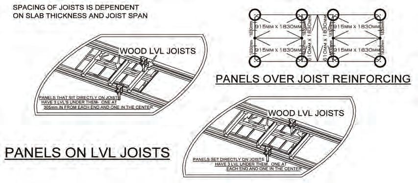
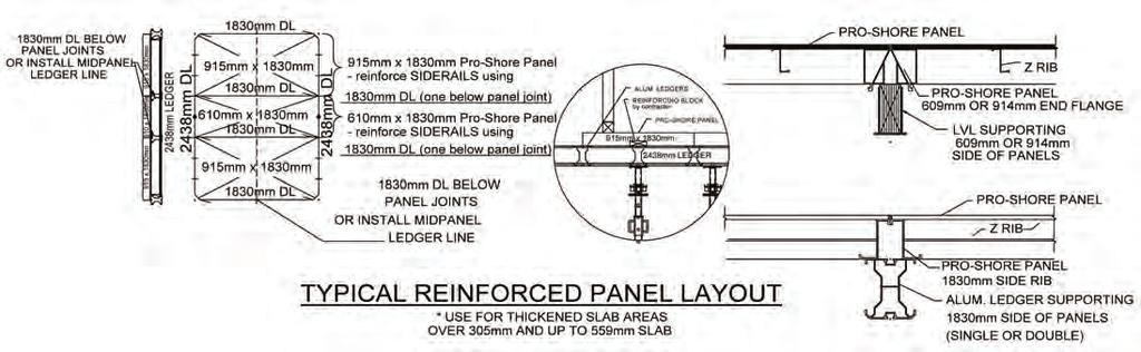
22 PRO-SHORE PANEL TYPICAL APPLICATION DETAILS Slab Conditions and Thicknesses Note: Contractor to ensure proper fall protection is provided on all open sides and openings in formwork and slabs as required by local and applicable codes. Column Conditions 21


23 22 Note: Contractor to ensure proper fall protection is provided on all open sides and openings in formwork and slabs as required by local and applicable codes.
24 Note: Contractor to ensure proper fall protection is provided on all open sides and openings in formwork and slabs as required by local and applicable codes. 23

25 Other Considerations 24


26 SLOPED SLABS When it is necessary to place Pro-Shore on sloped surfaces, additional bracing and analysis is required. If slopes are greater than 12%, contact the Dayton Superior Engineering Department. The drawings below are for illustrative purposes only. Each case is different. Note: Contractor to ensure proper fall protection is provided on all open sides and openings in formwork and slabs as required by local and applicable codes. 25
27 BRACING SLIDER To facilitate proper Cross-Bracing of Pro-Shore bearing on a sloped slab, the Brace Slider is attached to one or both of the posts. The Bracing Slider is attached at the Jet-Lok locations of the post shores. The Cross-Braces are then attached to the Brace Slider and pivoted into position to the adjacent post shore. Note: Contractor to ensure proper fall protection is provided on all open sides and openings in formwork and slabs as required by local and applicable codes. Contact Dayton Superior for slopes grater than 12% (7 ). 26
28 MINIMUM & MAXIMUM SHORE HEIGHTS Product Code Post Fully Closed Height Universal Drophead (lowered) Universal Drophead (Raised) F57073 Primary Post 2.0m 2.1m 3.3m 2.2m 3.3m N/A Primary Post w/ 0.6m Extension 2.6m 2.7m 3.9m 2.8m 3.9m F57075 #3 Post Shore 2.4m 3.1m 3.6m 2.5m 3.6m 27