SLAB AND WALL ANALYSIS AND DESIGN. Angel Francisco Martinez Civil Engineer MIDASoft
|
|
|
- Percival Sanders
- 5 years ago
- Views:
Transcription


1 SLAB AND WALL ANALYSIS AND DESIGN Angel Francisco Martinez Civil Engineer MIDASoft

2 Dimensions 8m 54ft 2m 93 ft 8.8m 2m 2m 2.8m 24 m 9m 171 ft


3 Define Properties Define Material -Concrete ASTM C4500 Define 4 rectangle Sections as shown H B Column 0.2 m 0.2 m Slab girder 0.15 m 0.15 m Raft girder 0.3 m 0.3 m Wall marker.001 m.001 m 3 thicknesses as shown Raft Wall Slab Thickness 0.3 m 0.2 m 0.15 m


4 Import DXF CAD Layers Import Slab and Wall DXF Select Wall Layer and assign wall marker section Select Raft Layer and assign raft girder section Select Slab Layer and assign slab girder section


5 Extrude Columns Extrude columns Assign Element Type: General beam Section: Column Select center slab layer nodes as shown Extrude: -2.8 m


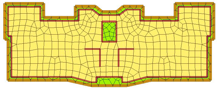
6 Mesh Slab Auto Mesh Planar Area Method: Line Elements Element Type: Plate Thickness: 0.15 Select Slab and Wall layers Mesh size 1m Domain: Slab


7 Extrude Walls Extrude walls Extrude Type: Line Elem to Planar Element Assign Element Type: Plate Thickness 0.2m Select center wall layer From work tree 2 Extrude: -2.8 m
8 Extrude Walls Extrude walls Extrude Type: Line Element to Planar Element Assign Element Type: Plate Thickness 0.2m Select center wall layer From work tree 2 Extrude: -2.8 m


9 Mesh Raft Auto Mesh Planar Area Method: Line Elements Element Type: Plate Thickness: 0.3m Select All Bottom nodes Mesh size 1m Domain: Raft


10 Load Cases Static Load Cases Create 4 load cases Assign Self Weight to dead load case


11 Assign Pressure Loads Assign pressure load to slab Load Case: Live Element type: Plate Assign a -7 kn/m^2 load to 0.15 thick slab


12 Building Generation Make copies of the first floor Select All except raft elements Copy 3 times at 2m Click Add Click Apply


13 Mesh Wall Auto Mesh Planar Area Method: Planar Elements Element Type: Plate Thickness: 0.2 m Select All 0.2m thick elements Mesh size 1m Domain: Wall


14 Generate story data Auto Generate Story Data Convert Self weight into Masses


15 Wind Load X Add Wind Load Load > Static Loads > Lateral > Wind Loads > Click [Add] Load Case: Wind X Wind Load Code: IBC 2012 Exposure: C X Direction Scale Factor 1 Accidental Eccentricity X Direction Positive Inspect Wind Load Profile


16 Wind Load Y Add Wind Load Load > Static Loads > Lateral > Wind Loads > Click [Add] Load Case: Wind Y Wind Load Code: IBC 2012 Exposure: C Y Direction Scale Factor 1 Accidental Eccentricity Y Direction Positive Inspect Wind Load Profile


")
17 Response Spectrum Functions Seismic Load Load > Seismic > Response Spectrum Data > Response Spectrum Functions Click Add Click Design Spectrum Generate Design Spectrum: IBC2012(ASCE7-10)

![IBC2012(ASCE7-10) Check: Accidental Eccentricity Click [Add]](/docs-images/89/98079128/images/18-2.jpg "Load Cases Name : RY Excitation Angle : 90 > Click [Add] Check:")
![Accidental Eccentricity Click [Eigenvalue Analysis control]](/docs-images/89/98079128/images/18-3.jpg "Number of Frequencies: 15 > Click [OK] Click [Close] Response")
18 Seismic Load Load > Response Spectrum Data > Response Spectrum Load Cases Load Case Name: RX Excitation Angle : 0 Check : IBC2012(ASCE7-10) Check: Accidental Eccentricity Click [Add] Load Cases Name : RY Excitation Angle : 90 > Click [Add] Check: Accidental Eccentricity Click [Eigenvalue Analysis control] Number of Frequencies: 15 > Click [OK] Click [Close] Response Spectrum Load Cases


19 Add Spring Supports Add Surface Springs Element Type: Planar Spring Type: Linear Kx = Ky = 1,500 Kz = 15,000 kn/m^3 Select Raft thickness 0.3 m Click Apply Boundary Condition


20 Load combination Generate Load Combo Results > Combinations > Concrete Design > Auto Generation Select Concrete and Design Auto Generation Design Code: ACI318-14

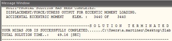
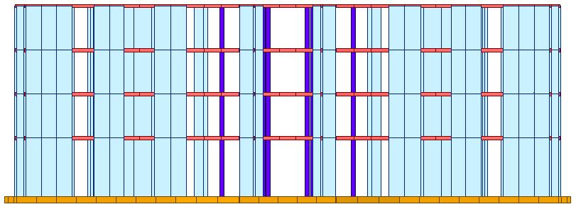
21 Perform Analysis
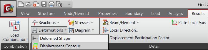
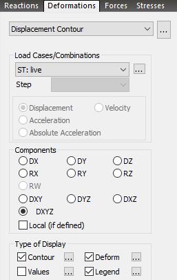
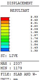
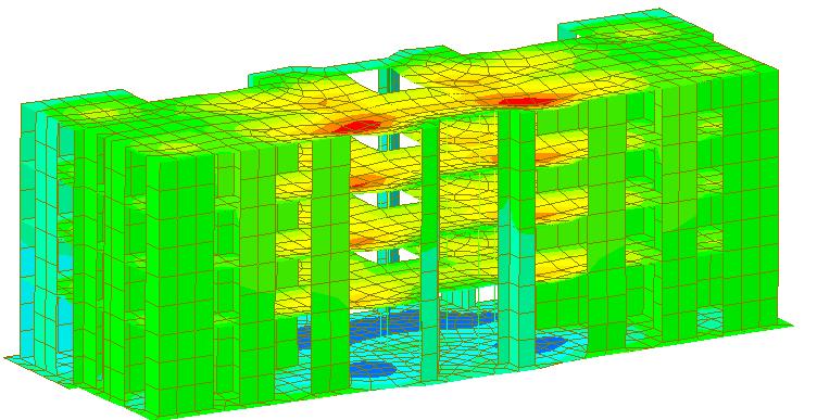
22 Results: Deformations


23 Results: Axial Plate Forces

24 Results: Moments Y

25 Results: Shear Forces


26 Slab and wall load combinations Slab/Wall Load Combination Select the load combinations for the slab/wall element design. Design > Design > Meshed Design > Slab/Wall Load Combinations Select the 1 st load combination in each column to consider during the slab/wall design.


27 Define Design Criteria for Rebar Specify rebar size Enter the standard sizes of rebars used in the design of reinforcement for slab/wall elements. Design > Design > Meshed Design > Design Criteria for Rebar Check off [Basic Rebar for Slab] For Slab Design: Dir. 1 : 0.03 m, 0.03 m Dir. 2 : 0.05 m, 0.05 m For Wall Design Face to Center Rebar 0.02m

28 Slab/Wall Rebar Checking Data Specify rebar size Select all slabs from tree menu Layer Top Dir 1 Add rebar 1: 100mm Add rebar 2: #3 Add/Replace

29 Slab/Wall Rebar Checking Data Specify rebar size Select all 0.2m walls from tree menu Layer Top Dir 1 Vertical 1: 100mm Horizontal 2: 100mm Add/Replace


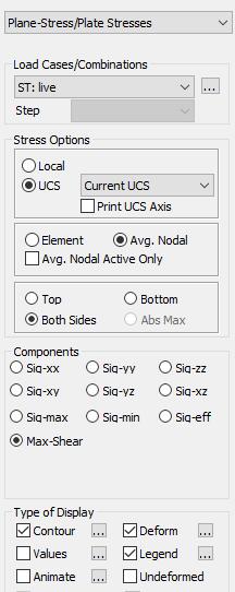
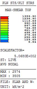
30 Slab Flexural Design Run Design Select Avg. Nodal Dir. 1 Resistance Ratio : The ratio of the design moment to the moment resistance when the designed rebar spacing is applied.

31 Slab Flexural Design
32 Slab Flexural Design
33 Slab Flexural Design
34 Slab Flexural Design
35 Slab Flexural Design
36 Slab Flexural Design
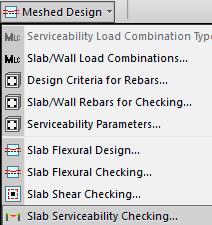
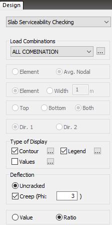
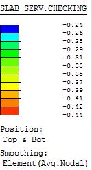
37 Slab Serviceability Check Run Check Check UnCracked Creep Phi : 3 Ratio
 check")

38 Slab Shear Checking Run Check Check on Punching Shear Check Slab Shear Checking Produce the two-way shear (punching shear) check results at the supports of slab elements or at concentrated loads and the one way shear check results along the user-defined Shear Check Lines
39 Slab Shear Checking
40 Slab Shear Checking
41 Slab Shear Checking
42 Slab Shear Checking
43 Slab Shear Checking
44 Slab Shear Checking
45 Slab Shear Checking


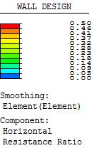
46 Wall Design Run Design Specify Design Criteria as Resistance Ratio
47 Wall Design

48 Wall Design


49 End