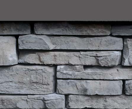
shaped for imagination
|
|
|
- Briana Cook
- 5 years ago
- Views:
Transcription

1 Installation Guide Straight or curved garden, retaining & seat walls steps pillars planters tree-rings fireplaces fire-pits water features grill islands BBQ s


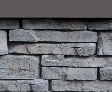
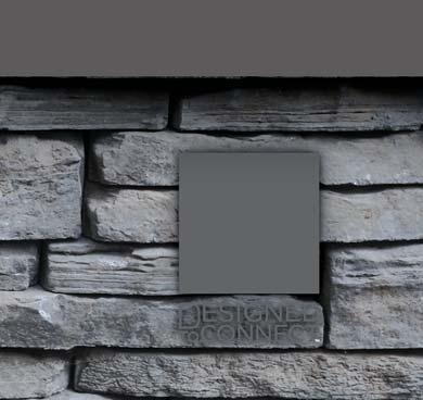
2 S-Shape Design shaped for imagination The Rivercrest Wall System incorporates engineered, patent pending design with natural beauty and contractor friendly design features. For the professional landscaper or do-it-yourselfer, Rivercrest offers the look & character of natural fl agstone but without the cost and diffi culty of installation. Unit No. Reference Hollow Auto-Alignment Core Stone Textured Face Auto-Alignment Knob S-Shape Design Side-A Reference Stone Textured Face Side-B Reference Rivercrest Wall System integrates a collection of sizes including 4 standard, 4 jumper, 2 corner and 1 coping units, featuring over a hundred distinct stone face textures. The unique shape, array of unit sizes and random natural stone textures allows you to create virtually any design you can imagine. Installation and estimation is simple. Standard No.1 Standard No.2 Standard No.3 Standard No.4 20 x x 5.7cm 8" x 9-10" x 2.25" 31 x x 5.7cm 12" x 9-10" x 2.25" 31 x x 5.7cm 12" x 9-10" x 2.25" Integrated Alignment Knob 42 x x 5.7cm 16.5" x 9-10" x 2.25" Integrated Alignment Knob Jumper No.1* Jumper No.2* Jumper No.4* Corner Jumper* 20 x x 11.4cm 8" x 9-10" x 4.5" 31 x x 11.4cm 12" x 9-10" x 4.5" 42 x x 11.4cm 16.5" x 9-10" x 4.5" 31 x x 11.4cm 12" x 9-10" x 4.5" Long Corner Short Corner Long Coping 31 x x 5.7cm 12 x 9-10" x 2.25" 25 x x 5.7cm 10" x 9-10" x 2.25" 56 x 28 x 5.7cm 22" x 11" x 2.25 *Jumper units are not available as a stock item in all regions. Please check with your area representative for availability. 1


 pallet confi gurations containing separate units.")


3 pallet configurations Stones & Bundles Face ft/ Bundle Face ft/ Unit Lin ft/ Bundle Lin ft/ Unit Units/ Bundle Units/ Face ft Layers/ Bundle Lbs/ Unit Lbs/ Bundle Random Wall Bundle Standard No Standard No Standard No Standard No Jumper Wall Bundle Jumper No Jumper No Jumper No Corner Jumper Bundle Corner Bundle Long Corner Short Corner Long Coping The Rivercrest Wall System has fi ve (5) pallet confi gurations containing separate units. All Standard and Jumper Units come bundled and randomized for quick easy installation. Refer to Rivercrest Estimation Guide for more information on pallet quantities. Standard Unit Pallet Jumper Unit Pallet* No.4 No.1 No.3 No.2 Jp.4 Jp.1 Jp.2 Corner Jumper Unit Pallet* Corner Unit Pallet Long Coping Unit Pallet Long Corner Short Note: Corner and Coping units can also be mixed with standards units within a wall. *Jumper units are not available as a stock item in all regions. Please check with your area representative for availability. 2


 and reverse the order every other course to avoid any confl icts.")


4 installation techniques There are no specifi c laying patterns with the Rivercrest Wall System. Simply keep the following guidelines in mind and use up equal numbers of all units. If you run into a confl ict where a knob does not fall into a core, just knock it off with a chisel and place a small amount of adhesive down or put a different unit down that works. For simplicity, you could lay the units as they come off the skid (No.4,1,3,2) and reverse the order every other course to avoid any confl icts. This would, however, reduce the variable look in the wall. straight wall align A-A / B-B curved wall align A-B / B-A auto-alignment With each consecutive course, alternate stones with & without alignment knobs. This unique alignment system helps you easily align units visually, and provides a mechanical system when building retaining walls. curve transitions The transition from a curve to a straight wall should occur as close as possible to the transition zone in the row below. Course 1 Course 2 Curve starting a wall Alternate between the Long Corner and Short Corner units on alternating courses to start a running bond pattern, this will minimize the chance of alignment knob not fi nding a core. Transition Zone Course 1 Curve Course 2 3
, and a short corner, 250mm (10\"), into account as these will be at either end.")

5 installation techniques unit increment Unit No.4 and Unit No.1 are the same length, 580mm (23"), as the combination of Unit No.3 and Unit No.2. This increment can be used to plan a layout between two set points such as corners. Make sure to take the length of a long corner, 312mm (12"), and a short corner, 250mm (10"), into account as these will be at either end. 580 mm jumper units In addtion to being used to enhance sections of wall, Jumper units can also be used in a variety of different ways within the Rivercrest Wall System. The Corner Jumper has faces on 3 sides, making it perfect for incorporating into pillars and corners. The unit can also be used when starting and ending seat walls. The number of jumper units you require will be determined by the look you wish to achieve, refer to Estimation Guide for more details. 580 mm retaining wall construction Coping H Recommended for retaining walls 600mm (2.0ft) and under as a gravity wall (no Geogrid). Higher walls may be constucted utilizing geogrid*. Wall to be constructed on a 100mm (4") by 500mm (20") granular footing with a min. of 1 course embedded. A drainage layer comprised of free draining material, with a depth equal to the height of the wall [min 300mm (12")] is required. A minimum 100mm (4") perforated drainage tile is also required. Over compaction of the drainage layer must be prevented. Standard Units H Dra Drainage Material Filter Cloth F Measurements in millimeters Note: It is recommended that all units be secured with an approved concrete adhesive. *For information on height limitations using geogrid, please contact Risi Stone Retaining Wall WALL or 4
 in height.")
 should extend back into the reinforcement zone at least 70% of the wall height, with")
6 retaining wall geogrid installation When building Rivercrest retaining walls higher than 2.0 ft (0.6m) in height, the use of an approved Polyester Geo - grid reinforcement is required. Geogrid must be properly installed according to manufacturer s specifi cations. Many building codes require an engineered design for retaining walls exceeding 3.0 ft (1.0m) in height.* The specifi c wall design will determine the precise Geogrid requirements. However a good rule of thumb when using Rivercrest, is that the Geogrid (length - including the 10"unit width) should extend back into the reinforcement zone at least 70% of the wall height, with Geogrid layered vertically every 5 6 courses (Approx. 12"). A high quality, washed ¼" angular chip (no fi nes) aggregate infi ll material is recommended for the reinforced zone behind the wall as this does not require signifi cant compaction immediately next to the units. When constructing a retaining wall with Rivercrest, the alignment core must be positioned directly touching the front of the alignment knob in the unit below, as shown (Fig.1). Therefore when installing, all units must be pushed back toward the reinforcement zone. This will guarantee the wall a very slight lean (batter), which is preferred when building higher retaining walls. Front Fig.1 Batter Reinforcment Zone There are 2 options available to properly construct a retaining wall with the Rivercrest Wall System. Either option will achieve the necessary connection of the Geogrid to the Rivercrest units, and maximize shear capacity. 1using adhesive Manufacturer Recommended 2using gravel fill Fig.2 Fig.3 Construct the wall as shown in Fig.1. For each course secure the wall by placing a bead of approved Concrete Adhesive along the top surface on the front and back of the units as shown (Fig.2). For Geogrid layers, lay the Geogrid ensuring it is secured in both beads of adhesive. Concrete adhesive must be applied in accordance with manufacturer s specifi cations. For each course, fi ll the unit alignment cores fl ush to the top with a washed ¼" angular chip aggregate. For Geogrid layers, lay the Geogrid so that the edge extends at least 1" past the alignment core towards the front edge of the unit. A washed ¼ angular chip aggregate is recommended because it is self-compacting, easy to handle, and has excellent frictional properties that interlock with the Geogrid. *Note: Contact Ristione Retaining Wall WALL or for more information & height limitations using Geogrid. 5


7 corner construction 1 first course 2 second course Fig.1 Fig.2 When constructing corners, abut the Long Corner unit with a Standard unit Side A. For the next course alternate the corner unit direction to automatically change the bond pattern. Continue to build the corner repeating Steps 1-2 or incorporate Step 3. 3 coping as a corner Fig.3 Coping units or short corner units may also be integrated into the corner to enhance the appearance and add stability. When constructing a seat wall, centre align the coping unit with the unit below; it will protrude slightly but add to the rustic appearance of the wall. In retaining walls the coping unit may be set back into the reinforcement zone, so that the front & side are fl ush with the rest of the corner. Simply remove the alignment knob with a chisel if there is a confl ict. Note: All components should be secured with approved concrete adhesive. 6
 to create a curve or circle with an outside radius of 2.9' (880mm). Using only Standard No.1 units, align Side A+B / B+ A.")


8 standard curves & circles 1 small curve/circle 2 medium curve/circle Use this pattern (fi g.1) to create a curve or circle with an outside radius of 2.9' (880mm). Using only Standard No.1 units, align Side A+B / B+ A. Use this pattern (fi g.2) to create a curve or circle with an outside radius of 3.5' (1060mm). Using only Standard No.1 & No.3 units, alternate units and align Side A+B/B+A. 3 large curve/circle Use this pattern (fi g.3) to create a curve or circle with an outside radius of 4.5' (1370mm). Using Standard No.1, No.2, No.3 & No.4 units, align Side A+B/B+A. A unit order of 1»4»2»3 will ensure an alignment knob on alternating units. Note: All components should be secured with Approved Concrete Adhesive. With the exception of small curves & circles, always try to alternate between units with and without alignment knob. 7
 to create a curve or circle with an outside radius of 2.9' (880mm). Using only Standard No.")
. Using only Standard No.1 & No.3 units, alternate units and align Side A+B/B+A.")

9 standard curves & circles coping cuts 1 small curve/circle 2 medium curve/circle Use this pattern (fi g.1) to create a curve or circle with an outside radius of 2.9' (880mm). Using only Standard No.1 units, align Side A+B / B+ A. Use this pattern (fi g.2) to create a curve or circle with an outside radius of 3.5' (1060mm). Using only Standard No.1 & No.3 units, alternate units and align Side A+B/B+A. 3 large curve/circle Use this pattern (fi g.3) to create a curve or circle with an outside radius of 4.5' (1370mm). Using Standard No.1, No.2, No.3 & No.4 units, align Side A+B/B+A. A unit order of 1»4»2»3 will ensure an alignment knob on alternating units. Note: All components should be secured with approved concrete adhesive. 8
 or No.2 Long Coping units (fi g.2). Using a Standard unit (SideA), abut the seat wall layer fl ush to pillar edge.")


10 integrated pillar & seat wall fl ush to edge 1 non-integrated layer 2 integration into corner unit layer Create pillar base by using No.4 Long Corner units as shown (fi g.1) or No.2 Long Coping units (fi g.2). Using a Standard unit (SideA), abut the seat wall layer fl ush to pillar edge. Place 3 Long Corner units as shown (fi g.3) and abut a Standard No.4 or No.1+2 unit so that the seat wall is now integrated into the pillar. Continue to build pillar/ seat wall by randomly using either integrated or non-integrated layers. 3 integration into coping unit layer Place a Long Coping unit as shown (fi g.4) and abut a Standard No.4 or No.1+2 unit so that the seat wall is now integrated into the pillar. To fi nish, cut another Long Coping unit to length, measuring fi t to accommodate the Standard unit rock face, approx. 125/8"(320mm). Continue to build pillar/seat wall by randomly using either integrated or non-integrated layers. Note: All components should be secured with approved concrete adhesive. 9
. Using a Standard unit (SideA), abut the seat wall to the centre of the pillar. Place 2 Long Corner units as shown (fi g.3) and abut a Standard No.")
. Continue to build pillar/ seat wall by randomly using either integrated or non-integrated layers.")
.")
11 integrated pillar & seat wall into centre 1 non-integrated layer 2 integration into corner unit layer Create pillar base by using 2 Long Coping (fi g.1) or 4 No.4 Long Corner (fi g.2). Using a Standard unit (SideA), abut the seat wall to the centre of the pillar. Place 2 Long Corner units as shown (fi g.3) and abut a Standard No.4 unit so that the seat wall is now integrated into the pillar. To fi nish, cut 2 Long Corner units to length, measuring fi t to accommodate the Standard unit rock face, approx. 6 3/8"(160mm). Continue to build pillar/ seat wall by randomly using either integrated or non-integrated layers. 3 integration into coping unit layer Place a Long Coping unit as shown (fi g.4) and abut a Standard No.4 unit so that the seat wall is now integrated into the pillar. To fi nish, cut both ends off another Long Coping unit, measuring fi t to accommodate the Standard unit rock face, approx. 6 3/8"(160mm). Continue to build pillar/seat wall by randomly using either integrated or non-integrated layers. Note: All components should be secured with approved concrete adhesive. 10
 or formula to calculate the number of steps and the Total Run you will require. When building Rivercrest retaining walls higher than 2.")
 aggregate infi ll material is recommended for the Zone under the steps to ensure proper compaction.")

12 integrated stairs with geogrid reinforcement Total Run The Rivercrest wall system has been designed to have a comfortable step tread depth of 11" (280mm) and a riser height of 7" (180mm). Use the height of the exposed wall and the chart (fi g.1) or formula to calculate the number of steps and the Total Run you will require. When building Rivercrest retaining walls higher than 2.0 ft (0.6m) in height, the use of an approved Polyester Geogrid reinforcement is required. Refer to Geogrid Installation for more information. A high quality, washed ¼" angular chip (no fi nes) aggregate infi ll material is recommended for the Zone under the steps to ensure proper compaction. Geogrid reinforcement is also recommended to add support and prevent settling issues. Exposed Wall Height 0 7" 14" 21" 28" 35" 42" 49" 56" 0 10" 11" 20" 30" 40" 50" 60" 70" 80" WALL Fig.1 Exposed Wall Height / 7" (180mm) = x 10" (255mm) = # of Steps Total Run (Rounded Up) 1 determine base size/layout 2 gravel fill Total Run Fig.2 Fig.3 Use the height of the exposed wall and the chart (fi g.1) or formula to calculate the number of steps and the Total Run you will require. Using the Total Run, measure out from the back of the wall unit and place a mark. This is where the front of the fi rst step support unit will go. Continue the next course as shown (fi g.3), integrating stones into the wall alternating between left and right side. At the course just below the step tread, fi ll the reinforced zone level with a washed ¼" angular chip gravel. Note: Always check with your local Building Code for min/max riser, tread dimensions, railing requirements and minimum embedment depth prior to planning out your steps. All components should be secured with approved concrete adhesive. 11
, ensuring it is fi rmly")
13 3 geogrid reinforcement 4 positioning the next step Total Run Tensile Strength Fig.4 Fig.5 Using approved concrete adhesive, glue a layer of Geogrid reinforcement so the tensile strength is aligned horizontally along the stairs (perpendicular to the sidewalls), ensuring it is fi rmly embedded in both beads of adhesive. This layer will help support the stairs above against settlement. Use the remaining wall height and the chart (fi g.1) or formula to calculate the Total Run for the next step. Using the Total Run, measure out from the back of the wall unit, this is where the front of the base for the next step will go. This step is especially important with higher retaining walls that have batter. Next, abut the coping units to the base units to create your tread, there should be no more than 1" (25mm) overhang. Repeat steps


14 coping units alternative uses 1 in a pillar 2 as a corner Fig.2 Fig.1 Fig.1 When constructing pillar coping units should be used throughout to break-up repeating bond patterns. A Coping layer should be place every 2-3 layers. For more information on constructing pillars see Integrated pillar guide Coping units may also be integrated into the corner to enhance the appearance and add stability. When constructing a seat wall, centre align the coping unit with the unit below; it will protrude slightly but add to the rustic appearance of the wall. In retaining walls the coping unit may be set back into the reinforcement zone, so that the front & side are fl ush with the rest of the corner. Simply remove the alignment knob with a chisel if there is a confl ict. 3 in a wall 4 as a ledge Fig.3 Fig.4 When Integrating a Coping unit into a seat wall, centre align the coping unit with the unit below; it will protrude slightly but add to the rustic appearance of the wall. In retaining walls the coping unit may be set back into the reinforcement zone, so that the front is fl ush. Abut with short corner units on either side. Simply remove the alignment knob with a chisel if there is a confl ict. Ledges in your wall can add design and functionality. Place the Coping unit so that it overhangs approx "(60-75mm) and abut with short corner units on either side. Simply remove the alignment knob with a chisel if there is a confl ict. Larger ledges up to 4.5" (115mm) may be created in garden or retaining walls where the back of the wall will not be visible. Note: All components should be secured with approved concrete adhesive. 13

 10-12\" x 9-10\" x 2.25\" H 1 Pallet = 20.9 sq.ft (48 Long & 16 Short Units) 22\" x 11.75\" x 2.25\" H 1 Pallet = 89.1 lin.")
 Total Area ft X ft sq.ft Total # of Pallets Design Option Standard Units = 23 sq.ft = X 1 0.875 = 0.75 X Jumper Units 0 0.")

15 estimation guide Design Style To accurately determine the number of Standard and Jumper* units you will require, start by selecting an aesthetic Option. Quantity Options Option Option Option No Jumpers Some Jumpers Many Jumpers Standard Jumper* Jumper Corner* Corner Long Coping Sold by Pallet Sold by Pallet Sold by Pallet Sold by Pallet Use Corner Unit Design Option B Sold by Pallet Varied Sizes x 2.25" 1 Pallet = 23 sq.ft Varied Sizes x 4.5" 1 Pallet = 23 sq.ft 12" x 9-10" x 4.5" 1 Pallet = 12.2 sq.ft (32 Units) 10-12" x 9-10" x 2.25" H 1 Pallet = 20.9 sq.ft (48 Long & 16 Short Units) 22" x 11.75" x 2.25" H 1 Pallet = 89.1 lin.ft (48 Units) Estimate Calculator Using the Design Style Option of your choice, use the chart below to determine your wall unit requirements for purchase. Wall Units Wall Length Wall Height (excluding coping) Total Area ft X ft sq.ft Total # of Pallets Design Option Standard Units = 23 sq.ft = X = 0.75 X Jumper Units = Order Quantities Standard Pallets Jumper Pallets Corner Units X # of Corners on Project 9 12 = = X X Corner Units Corner Jumper Units = = Corner Pallets Corner Jumper Pallets Coping Units 89.1 lin.ft = Coping Pallets Note: All automatic calculations are rounded up to the nearest orderable quantities. *Jumper units are not available as a stock item in all regions. Please check with your area representative for availability. Rivercrest Estimation Guide
16 For more information & samples call today UNILOCK Boston Buffalo Chicago Cleveland Detroit Milwaukee New York Philadelphia Toronto Manufactured under licence from