the modern evolution Installation Guide Architextures Installation Guide v
|
|
|
- Gilbert Maxwell
- 5 years ago
- Views:
Transcription


1 TM the modern evolution Installation Guide Architextures Installation Guide v
2 TM
3 Contents This guide, provided at no cost by Risi Stone Inc. is intended to serve only as an informational resource for Architextures XL product purchasers. It is provided for reference only and is not a substitute for, and does not replace the need for registered professional engineering Design and experienced contractor installation. Risi Stone Inc. strongly urges purchasers to exercise diligence and care in the selection, design, installation and use of any construction materials. RISI STONE INC. DISCLAIMS ANY AND ALL LIABILITY FOR DAMAGES OR LOSSES OF ANY KIND OR NATURE TO PERSON(S) OR PROPERTY, INCLUDING, BUT NOT LIMITED TO, DIRECT, INDIRECT, INCIDENTAL, CONSEQUENTIAL OR PUNITIVE DAMAGES, ATTORNEYS FEES OR COSTS, ARISING OUT OF OR RELATED TO THE USE OF THE GUIDE, INCLUDING, BUT NOT LIMITED TO ANY WORK THAT MAY BE PERFORMED BY ANY CONTRACTORS OR INSTALLERS. BY USING THE GUIDE, YOU AGREE TO WAIVE ANY AND ALL CLAIMS AGAINST RISI STONE INC., ITS OFFICERS, DIRECTORS, EMPLOYEES, VOLUNTEERS, REPRESENTATIVES, CHAPTERS AND AFFILIATES, AND HOLD THEM HARMLESS FOR ANY DAMAGES OR LOSSES OF ANY KIND TO PERSON OR PROPERTY, INCLUDING, BUT NOT LIMITED TO, DIRECT, INDIRECT, INCIDENTAL, CONSEQUENTIAL OR PUNITIVE DAMAGES ARISING OUT OF OR RELATED TO THE USE OF THE GUIDE, INCLUDING BUT NOT LIMITED TO THE SELECTION, DESIGN, INSTALLATION OR USE OF ANY MATERIALS, STRUCTURES, COMPONENTS OR ASSEMBLIES. RISI STONE INC. and Architextures are trademarks of Risi Stone Inc Risi Stone Inc. All Rights Reserved. Introduction Overview of a Successful Project Understanding the Design Components of the Design ArchitexturesXL Modern Wall Features & Advantages Installation Details Corners Stairs Wall Construction Gravity Wall Installation Geogrid Reinforced Wall Installation Additional Construction Details Soil Conditions Drainage Posts, Guard Rails & Obstructions Version 1.0 \ Nov 1, 2017 Architextures Installation Guide v
4 Overview of a Successful Project The following Installation Guide has been provided to mainly address those aspects of Wall construction that are unique and/or proprietary to the Architextures Retaining Wall System. For all general Segmental Retaining Wall construction guidelines, Risi Stone Systems recommends the Contractor refer to the NCMA (National Concrete Masonry Association) Segmental Retaining Walls Best Practice Guide for the Specification, Design, Construction, and Inspection of SRW Systems. This excellent resource provides the comprehensive level of detail required for successful SRW Projects. Refer to The following procedure is recommended for the construction of segmental retaining walls over 36"(1m) in height, or as required by local building codes. Clear Plan Aboveground Site Assessment: existing grades, structures, utilities, property lines, visible water features, etc., established. Contact all utility companies to confirm location of underground utilities that may not be visible in aboveground assessment. Proposed site modifications defined by Designer (landscape architect, engineer, architect) based on owner s requirements and site limitations. Includes proposed grades, retaining wall geometry, slopes, proposed use of land (parking areas, water detention, landscape), relocation of existing structures/utilities, new structures/utilities, location of trees, etc. Project drawings generated and submitted to appropriate agencies for approval. Investigate local building codes and apply for all permits required. Assessment of Subsurface Conditions Geotechnical Investigation conducted to evaluate subsurface conditions of site, including soil types, characteristic properties, in-situ state, groundwater conditions, overall slope stability and bearing capacity. Recommended Design parameters, construction/excavation techniques, effects of proposed and existing structures, ground improvements, erosion protection, drainage considerations, anticipated settlement, etc., should be identified. Site-Specific Retaining Wall Design Grading Plan & Geotechnical Investigation provided to the Wall Design Engineer. Wall Design Engineer must be a Professional Engineer licensed in the applicable Province or State. The Design must synthesize all available information and include cross section and/or elevation view drawings, specifications, calculations, quantities, and related construction details. The Design should be checked for Global Stability by the site Geotechnical Engineer. Pre-Construction meeting For larger scale Projects, we recommend that all involved parties (Designers, Owner s representative, General Contractor, Contractor, Inspecting Engineer, Supplier, etc.) attend a pre-construction meeting to define schedule and clearly state responsibilities. Parties not directly involved with the Design and construction of the wall, but who may do future work that could influence the wall (e.g. paving, installing fences) should attend the meeting to understand the limitations of the wall and address precautions. Experience has shown that this simple step prevents a multitude of potential problems! Qualified Professional Engineer Hired for Inspection/General Review Inspection and General Review of the proposed SRW must be conducted by a qualified third-party engineer (called the General Review Engineer). As much of the General Review is Geotechnical in nature (compaction testing, soil and groundwater assessment) it often makes the most sense to have the Site Geotechnical Engineer conduct the General Review. Proper General Review of Construction should include all aspects of the installation. The scope of the GRE s responsibilities include, but are not limited to: Inspection of all materials used in construction (SRW units, backfill, drainage material, reinforcement, other structures). 4 Overview of a Successful Project Architextures Installation Guide v1.0
5 Understanding the Design Verification that the Design is compatible with the site in all respects. Identification of discrepancies between the plan and/or SRW Design and actual site conditions, and subsequent notification of Wall Designer. Continuous evaluation of site conditions, surface water and groundwater, compaction testing, foundation bearing capacity, excavation procedures, construction practices for safety and compliance with Design. Ensuring wall is constructed according to Design (geogrid lengths and type, Wall heights, etc). Finally, the GRE will provide a letter to the owner stating that the Wall was constructed in General Conformance with the Plans and Specifications". Proper Installation Adherence to Design, specifications, details, guides, and good construction practice is necessary. Conducted under supervision of the GRE. Final Grading Final grading should be conducted as soon as possible following construction to divert water away from the wall and create the optimum condition for great performance. Depending on the stage in the design process, there are generally three potential types of Design: Typical Design Not for Construction A Typical Design is a Non-Site-Specific Wall Cross Section or Design Table. Selected based on preliminary information regarding proposed maximum wall height, use of structure, grading, etc. Suitable for preliminary cost estimates, feasibility studies, and conceptual approvals. Not for Construction. Preliminary Design Not for Construction A site-specific Design produced for preliminary purposes when some component of the required design information is not yet available. Includes all elements needed to construct the wall, but is not considered ready for construction as it remains contingent on verification of some site-specific detail(s). Includes site-specific cross section drawings, elevation views, specifications, quantity calculations, details, statement of limitations, etc. Not sealed by the Designer. Final Design All necessary information has been established and the Design has been deemed ready for construction. This type of design is sealed by the Designer. Safety Notes Ensure all workers are well-versed in the proper use of all equipment and vehicles. Prior to each use, inspect all machinery to ensure that it is in good condition. Do not exceed the recommended load/speed/capacity specified by the equipment manufacturer. Ensure overall maintenance of all machinery is kept up. Follow all occupational health & safety guidelines set forth by your local government. Architextures Installation Guide v1.0 Overview of a Successful Project \ Understanding the Design 5
6 Components of the Design The Design should clearly provide all information necessary to construct the proposed SRW structure. The basic components are as follows: Design Notes / Limitations The Design should include information regarding the design standard used, limitations of design, status of design (preliminary or final), design assumptions, purpose of the wall, and potential construction issues. Cross Section Drawing(s) The cross section drawing is usually provided to illustrate the general arrangement of the wall, soil zones, assumed parameters, structural elements, water levels, etc. A cross section drawing is normally provided for the maximum height section through the wall and/or the most critical section. Additional cross sections may be provided to indicate variable conditions or wall orientation (terraces/location of structures) throughout. Details The cross section and elevation view drawings are to be used in conjunction with the related detail drawings. These may include handrails, corners, curves, stepping foundation, steps, etc. Adherence to these details is vital for optimum wall performance. Specifications The Design should include standard specifications that outline specific requirements of the Design, Construction, Materials, Certification, and Finishing. Elevation View Drawing(s) The elevation view or face" view of the wall depicts the wall as a whole, essentially laying the wall out flat on the page. This drawing details the overall geometry of the proposed wall, steps at the top and bottom of wall, required geogrid length and placement (where applicable), location of other structures, etc. Calculations and Quantity Estimates Most design reports contain a summary of quantities of Block, Geogrid, Infill, etc. The contractor is responsible for verifying the quantities provided by checking the most recent grading information, and/or site grading, against the elevation view provided. 6 Components of the Design Architextures Installation Guide v1.0
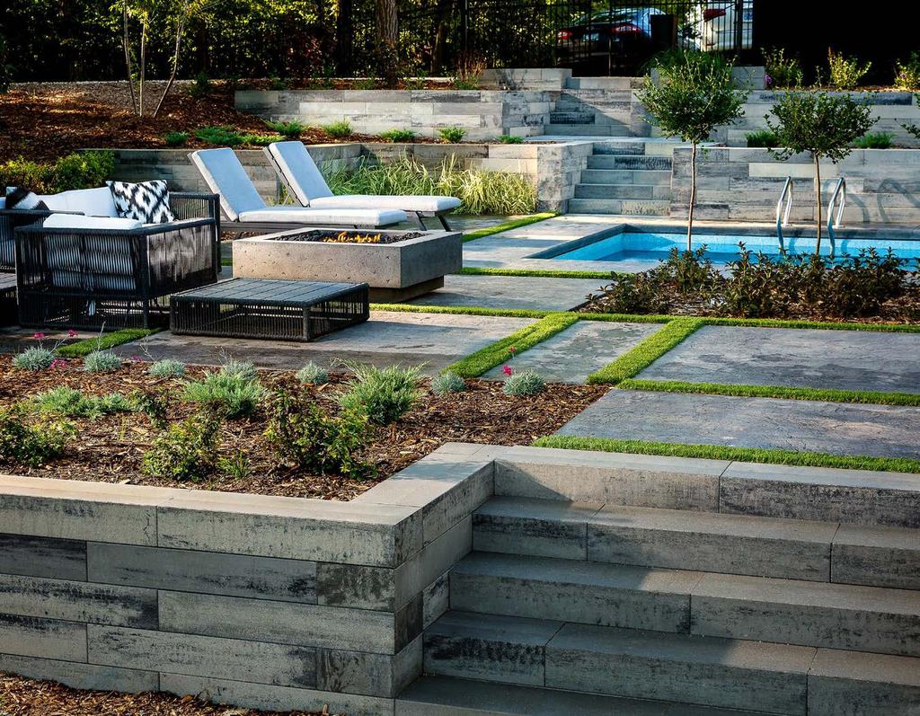
7 Architextures XL Modern Wall Features & Advantages The ArchitexturesXL system is a modular concrete retaining wall system that is used to stabilize and contain earth embankments, large and small. The ArchitexturesXL Wall System is a fully engineered, Structural Retaining Wall System. Constructed as either a Gravity wall (no geogrid) or a Geogrid Reinforced Wall, ArchitexturesXL can be used for applications up to 13ft(4m) or even higher with proper Design. The Unique appearance of ArchitexturesXL also makes it ideal for smaller Landscape type applications, such as garden walls, raised patios, or planters. The ArchitexturesXL system has a number of features that make it unique. They have been developed to enable a faster and more accurate installation by the contractor and to provide a stronger, more beautiful and more economical structure for the owner. Feature Near-vertical batter Benefit Expands usable site only 1/8"(3mm) setback per course Makes a smooth and precisely-aligned wall face ArchitexturesXL Blocks Width Height Depth Weight Standard Integral Tongue and Groove Design No separate pins or clips to install Shear strength is maintained along the entire length of the block Universal Corner Coping 35.5" / 90cm 5.9" / 15cm 11.25" / 28.5cm 165lbs / 75kg 35.5" / 90cm 5.9" / 15cm 11.25" / 28.5cm 155lbs / 70kg 35.5" / 90cm 5.9" / 15cm 11.25" / 28.5cm 176lbs / 80kg Solid Block DeadNuts Technology Appearance Ensures maximum weight of each block is present Reduced installation time & labour costs Maximum resistance to overturning Excellent freeze/thaw durability Precisely controlled height tolerance, reduces the need to level and shim courses Manufacturing process allows for limitless colour options, and facing textures Closed-End Coping 35.5" / 90cm 5.9" / 15cm 11.25" / 28.5cm 176lbs / 80kg The ArchitexturesXL system utilizes a universal corner block that is used for both left and right corners by flipping the block. Each skid layer of coping includes a left & right closed-end coping. These can be used normally in a wall by using a hammer to remove the closed-end section of the groove. Architextures Installation Guide v1.0 ArchitexturesXL Modern Wall \ Features & Advantages 7


8 Outside 90 Corners First Course 1 Continue Building 3 Place blocks on the base course leading to the corner and use a corner block. Repeat until desired wall height is achieved. Finish the corner off with a closed-end coping block. Second Course 2 Geogrid Installation 4 Commence second course by flipping a corner block and placing it in the alternate direction. Place standard blocks to complete the course. Overlap geogrid as shown where the Design requires. 8 Installation Details - Outside 90 Corners Architextures Installation Guide v1.0


9 Inside 90 Corners First Course 1 Continue Building 3 Place blocks on the first course leading to the corner and use a corner block. Repeat until desired wall height is achieved. Finish off with coping blocks. Second Course 2 H/4 Geogrid Installation 4 Commence the second course by flipping a corner block and placing it in the alternate direction. Place standard blocks to complete the course. The geogrid should be placed within 1"(2.5cm) of the face of the block. As it is only necessary to have geogrid extending directly away from the wall, a gap will result in the geogrid layer as shown. Alternate direction of geogrid reinforcement H/4 extension on subsequent geogrid layers. Architextures Installation Guide v1.0 Installation Details - Inside 90 Corners 9
] Using two standard blocks, prepare and cut the blocks as shown. Mark the first block insetting the cut line 11.25\"(28.5cm) (Block Depth) from the front edge.")


10 Outside 45 & Odd Angle Corners Saw Cut Half of Corner Angle Cutting Blocks 1 Second Course 3 Half of Corner Angle Saw Cut Block Depth [11.25"(28.5cm)] Using two standard blocks, prepare and cut the blocks as shown. Mark the first block insetting the cut line 11.25"(28.5cm) (Block Depth) from the front edge. The angle of the cut should be half the angle of the final wall corner (eg for a 45 corner). Cut the second block at the same angle on the oposite side starting from the front corner. Commence second course by cutting the blocks on the opposite side so when installed, it will create an overlapping bond pattern as shown. Place the cut blocks in the corner and use standard blocks to complete the course. First Course 2 Continue Building 4 10 Place blocks on the base course leading to the corner and use the cut corner blocks. Place standard blocks to complete the course. Place a small piece of Geogrid with adhesive every course to maintain the corner's integrity. Installation Details - Outside 45 & Odd Angle Corners Repeat until desired wall height is achieved. Finish off with two cut coping units. Architextures Installation Guide v1.0


11 Inside 45 & Odd Angle Corners Cutting Blocks 1 Second Course 3 Saw Cut Corner Angle Using one standard block prepare and cut the blocks as shown. The angle of the cut should be the same angle as the final wall corner. Cut the block starting from the front corner. Commence second course by cutting the block on the opposite side so when installed, this will create an overlapping bond pattern as shown. Flip and place a corner block in the alternate direction. Place the cut block in the corner and use standard blocks to complete the course. First Course 2 Continue Building 4 Block Depth 11.25"(28.5cm) Place blocks on the base course leading to the corner. Place the cut block and align a corner block as shown, insetting corner block a minimum of 11.25"(28.5cm) (Block Depth) from the edge. Place standard blocks to complete the course. Repeat until desired wall height is achieved. Finish off with two cut coping units. The angle of the cut for the coping blocks should be half the angle of the final wall corner (eg for a 45 corner). Architextures Installation Guide v1.0 Installation Details - Inside 45 & Odd Angle Corners 11
12 Inset Stairs The following steps provide guidelines for the construction of protruding or outside stairs. Proper compaction within the walls and under the treads, along with the use of geogrid to prevent settlement, is critical to the long-term performance. Ensure to consult your local Building Codes for limitations on Riser Height, Step Tread dimensions and handrail requirements. All stair components should be secured with approved concrete adhesive. Number of Steps = Total Height / 5.9"(15cm) Total Run = [Number of Steps - 1] x Tread Depth] First Step 2 Total Run Cross Section 1 Start the wall with two outside 90 corners (page 8) distanced as specified in the Design. Place coping blocks between to form the first step riser, measure and cut if required. Place another row of coping blocks back-to-back directly behind the first set. Tread Depth Gravel Fill & Compaction 3 Total Height Geogrid Reinforcement Two Coping blocks placed back-to-back To prevent settlement, it is recommended to include geogrid reinforcement within each course of steps. Fill the reinforced zone with imported, free draining gravel and compact to 95% SPD. It is recommended to use a washed ¼" angular chip gravel. This material requires less rigorous compaction and will help prevent outward movement of the blocks due to compaction pressures during construction. (ASTM#8) 12 Installation Details - Inset Stairs Architextures Installation Guide v1.0


13 Geogrid Layer 4 Repeat 6 Experience has shown that the inclusion of geogrid reinforcement within each course of steps reduces the effect of settlement. Repeat until desired wall height is achieved. Finish off with coping blocks. Second Step 5 TIP: For a larger tread depth, setback the steps as shown Place the next course back to the desired tread depth. For best results offset the cuts to create a bond pattern with the step below. Fill the reinforced zone with imported, free draining gravel and compact to 95% SPD. Place a geogrid reinforcement layer. Architextures Installation Guide v1.0 Installation Details - Inset Stairs 13

14 Protruding Stairs The following steps provide guidelines for the construction of protruding or outside stairs. Proper compaction within the walls and under the treads, along with the use of geogrid to prevent settlement, is critical to the long-term performance Ensure to consult your local Building Codes for limitations on Riser Height, Step Tread dimensions and handrail requirements. All stair components should be secured with approved concrete adhesive. Number of Steps = Total Height / 5.9"(15cm) Total Run = [Number of Steps - 1] x [Tread Depth - 1/8"(0.3cm)] Total Run First Step 2 Total Run Tread Depth Cross Section 1 Start the wall with two inside 90 corners (page 9) and two outside 90 corners (page 8) using closed-end coping blocks. Use the Total Run formula to determine the distance out from the face of the wall where the front of the first riser should be placed. Place another row of coping blocks back-to-back directly behind the first set. Gravel Fill & Compaction 3 Total Height Geogrid Reinforcement Two Coping blocks placed back-to-back To prevent settlement, it is recommended to include geogrid reinforcement within each course of steps. Fill the reinforced zone with imported, free draining gravel and compact to 95% SPD. It is recommended to use a washed ¼" angular chip gravel. This material requires less rigorous compaction and will help prevent outward movement of the blocks due to compaction pressures during construction. (ASTM#8) 14 Installation Details - Protruding Stairs Integrated Architextures Installation Guide v1.0

15 Geogrid Layer 4 Repeat 6 Experience has shown that the inclusion of geogrid reinforcement within each course of steps reduces the effect of settlement. It is recommended to include an additional geogrid layer every other step placed in the perpendicular principle direction. Repeat until desired wall height is achieved. Finish off with coping blocks. Tread \ Coping Units 5 TIP: For a larger tread depth, setback the steps as shown Place the next course back to the desired tread depth. For best results offset the cuts to create a bond pattern with the step below. Fill the reinforced zone with imported, free draining gravel and compact to 95% SPD. Place a geogrid reinforcement layer. Architextures Installation Guide v1.0 Installation Details - Protruding Stairs Integrated 15

 setback per course (approx.")
16 Gravity Wall Installation The following are the basic steps involved in constructing a conventional (non-geogrid reinforced) ArchitexturesXL segmental retaining wall. These steps are to be used in conjunction with all relevant details. Refer to Overview of a Successful Project before beginning. Excavate 2 12" 30" 16 Gravity Wall Installation Planning Your Wall With your final Design in hand, begin to establish the wall location and proposed grades. Locate all utilities and contact local utility companies before digging. Mark a line where the front of the wall will be placed, keeping in mind the 1/8"(3mm) setback per course (approx. 1 wall batter). Excavate the Base Excavate a trench down to the foundation grades specified in the Design. The front of the trench should be 6"(15cm) from the planned face of the wall. The trench should be a minimum of 30"(75cm) wide (front to back) and a minimum 12"(30cm) deep. This depth assumes at least one block is buried (NCMA requires a minimum 6" embedment) plus the compacted granular base (minimum depth of 6"). As wall height increases, the depth of embedment also increases, normally about 10% of the wall height. Greater embedment depths may be required to account for slopes more than 3H:1V in front of the wall, scour protection in water applications, global stability, or as specified in the Design. The rear 6" of the trench is excavated to account for the drainage layer. Excavations should be conducted in accordance with local codes under direction of the General Review Engineer (GRE). Architextures Installation Guide v1.0

 or as required by the GRE to reach competent founding soil. At the direction of the GRE, geotextile might be required under the granular base.")
17 Prepare the Base 4 Step the Base 5 6" Block Depth 6" Verify Foundation Subgrade Once the foundation trench has been excavated to the specified elevations, the native foundation soil must be checked by the GRE. The foundation soil must have the required allowable bearing capacity specified in the Design. Prepare the Compacted Granular Base Start the base at the lowest elevation of the wall. The base should be composed of well-graded, well-draining (less than 8% fines), angular granular material (commonly referred to as ¾" minus or road base) and compacted to a minimum of 98% SPD. The minimum base thickness is 6"(15cm) or as required by the GRE to reach competent founding soil. At the direction of the GRE, geotextile might be required under the granular base. The minimum base dimensions are 22"(55cm) wide (front to back) and 6" deep. The additional 6" trench width allows for the placement of the drain. Step the Base When the grade in front of the wall slopes up or down, the base must be stepped to compensate. The foundation steps must be located to ensure the minimum embedment is achieved. The height of each step is the block height of the course. The 1/8"(3mm) offset must be accounted for at each step (approx. 1 wall batter). TIP: A layer of unreinforced concrete 2"(5cm) thick may be placed on top of the granular material to provide a durable leveling surface for the base course. Architextures Installation Guide v1.0 Gravity Wall Installation 17
. Stake the filter cloth against the slope during construction.")

18 Place Filter Cloth 6 Place the Drain 7 Place Filter Cloth Lay the approved filter fabric (geotextile) along the bottom of the rear of the trench and extend up the exposed excavation to the proposed wall height. Leave adequate material at the top to fold back towards the wall (completely containing the drainage material). Stake the filter cloth against the slope during construction. In some cases, if the Design permits, the Filter Fabric requirement can be avoided if the Drainage Material is graded to promote a natural soil filter system. TIP: For more information on proper drainage requirements, refer to the Drainage information on page 30. Place the Drain Various options for drain placement may exist, depending on how the pipe is to be outlet (refer to Drainage page 30). The drain may be outlet through the wall face or connected to a positive outlet (storm drain). The drainage system is extremely important and outlets must be planned prior to construction. In the case of connecting to a positive outlet, the drain should be placed at the lowest possible elevation and sloped at a minimum of 2%. At the rear of the base, allow the granular material to slope down on the sides towards the drain trench. In the 6"(15cm) area behind the base, place the approved drain tile (perforated drain with filter sock) on top of the filter cloth and minimal granular coverage. 18 Gravity Wall Installation Architextures Installation Guide v1.0
 Place the First Course Position a level string to mark the location of the back of the first course, which would be a distance equal to the block depth from the proposed Face of Wall.")

19 Install First Course 8 Stacking Blocks " (28.5cm) Place the First Course Position a level string to mark the location of the back of the first course, which would be a distance equal to the block depth from the proposed Face of Wall. Place the first course of ArchitexturesXL blocks side-by-side (touching) on the granular base. Ensure blocks are level front to back and left to right. Extra care should be taken at this stage as it is critical for accurate alignment. Stacking Blocks Sweep top of underlying course and stack next course in a running bond pattern. ArchitexturesXL uses a modern 1/3 bond pattern which can be achieved by offsetting adjacent course by the 11.25"(28.5cm). Tip: For proper alignment, ensure all blocks are pushed fully forward to engage the shear key. Architextures Installation Guide v1.0 Gravity Wall Installation 19
 thick and protected from the native material by the filter cloth or as required by the Design.")

20 Backfilling 10 Stacking & Backfilling 11 Backfill Drainage Material A free-draining, gap-graded gravel (¼- ¾" washed, angular) drainage material is placed immediately behind the wall facing and compacted with a light manual tamper. The drainage layer must be a minimum of 12"(30cm) thick and protected from the native material by the filter cloth or as required by the Design. Continue Stacking and Backfilling Continue stacking blocks and backfilling as described until the desired height is reached, based on the Design. Place Coping Units A layer of concrete adhesive must be applied to the top course in order to fix the coping units in place. Place the coping unit firmly on top of the adhesive, ensuring both surfaces are free of debris, and apply pressure to secure. Follow the adhesive manufacturer s installation guidelines. 20 Gravity Wall Installation Architextures Installation Guide v1.0
 over the top of the drainage layer and extend up the back face of the coping unit.")
21 Finish Grading 13 TIP: For more information on proper swale requirements, refer to the swale information on page 32. Encapsulate the Drainage Layer and Finish Grading Fold the excess filter fabric (if required) over the top of the drainage layer and extend up the back face of the coping unit. Ideally, place an impervious layer of soil on top of the filter fabric and compact manually, providing for the required grading and/or swales. For other treatments such as pavers, concrete, or asphalt, care must be taken to ensure that heavy compaction/paving equipment remains a minimum of 36"(1m) from the back of the coping unit. Slope the surface above and below the wall to ensure that water will flow away from, and not accumulate near the wall units. Architextures Installation Guide v1.0 Gravity Wall Installation 21

 setback per course (approx.")
22 Geogrid Reinforced Wall Installation The following are the basic steps involved in constructing a Geogrid Reinforced ArchitexturesXL segmental retaining wall. These steps are to be used in conjunction with all relevant details. Refer to Overview of a Successful Project before beginning. Excavate 2 12" 30" Geogrid Length + 6" Plan With your final Design in hand, begin to establish the wall location and proposed grades. Locate all utilities and contact local utility companies before digging. Mark a line where the front of the wall will be placed, keeping in mind the 1/8" (3mm) setback per course (approx. 1 wall batter). Excavate Reinforced Zone The excavation must be carefully planned; considering several elements. Based on the type of soil being excavated, the GRE must determine the maximum allowable cut" angle the excavation can sustain. This angle ensures the stability of the excavation during construction. The required geogrid length (as shown in the Design) plus 6"(15cm) defines the minimum width at the base of the excavation. Measuring from 6" in front of the wall face, extend a line back the base width determined above. At the rear of the base dimension, an imaginary line should be extended up the slope at the allowable angle. Where this line breaks the slope surface is the beginning of the excavation. Excavation must then begin at the top of the slope and progress downwards at the acceptable angle. Excavation continues until the slope is cleared and a flat area at the base is exposed extending 6" past the proposed face of the wall. 22 Geogrid Reinforced Wall Installation Architextures Installation Guide v1.0
 wide (front to back) and mini mum 12\"(30cm) deep.")

23 Excavate Granular Base Excavate a trench for the granular base. The front of the trench should be 6"(15cm) from the planned face of the wall. The trench should be a minimum of 30"(75cm) wide (front to back) and mini mum 12"(30cm) deep. This depth assumes at least one block is buried (NCMA requires a minimum 6" embedment or 10% of wall height) plus the compacted granular base minimum depth of 6". As wall height increases, the depth of embedment also increases, normally about 10% of the wall height. Greater embedment depths may be required to account for slopes more than 3H:1V in front of the wall, scour protection in water applications, global stability, or as specified in the Design. The rear 6" of the trench is excavated to account for the drain. Verify Foundation Subgrade Once the wall has been excavated, the native foundation soil must be checked by the GRE. The foundation soil in a geogrid reinforced SRW is considered to be the native (or fill) material underneath both the facing and reinforced zone. The foundation soil must have the required allowable bearing capacity specified in the Design as verified by the GRE. 6" Block Depth 6" Prepare the Base Prepare the Compacted Granular Base The base should be started at the lowest elevation of the wall. The base should be composed of well-graded, well-draining (less than 8% fines), angular granular material (commonly referred to as ¾" minus or road base) and be compacted to a minimum of 98% SPD. The minimum base thickness is 6"(15cm) or as required by the GRE. The minimum base dimensions are 22"(55cm) wide (front to back) and 6" deep. The additional 6" trench width allows for the placement of the drain. 5 Step the Base 6 Step the Base When the grade in front of the wall slopes up or down, the base must be stepped to compensate. The foundation steps must be located to ensure the minimum embedment is achieved. The height of each step is the block height of the course. The 1/8"(3mm) offset must be accounted for at each step (approx. 1 wall batter). TIP: A layer of unreinforced concrete 2"(5cm) thick may be placed on top of the granular material to provide a durable leveling surface for the base course. Architextures Installation Guide v1.0 Geogrid Reinforced Wall Installation 23
.")

24 Place Filter Cloth 7 Place the Drain 8 Place Filter Cloth (as required by Design) Lay the approved filter fabric (geotextile) along the bottom of the rear of the trench and extend up the exposed excavation to the proposed wall height. Leave adequate material at the top to fold back towards the wall (completely containing the drainage material). Stake the filter cloth against the slope during construction. In some cases, if the Design permits, the Filter Fabric requirement can be avoided if the Drainage Material is graded to promote a natural soil filter system. TIP: For more information on proper drainage requirements, refer to the Drainage information on page 30. Place the Drain Various options for drain placement may exist, depending on how the pipe is to be outlet (refer to Drainage page 30). The drain may be outlet through the wall face or connected to a positive outlet (storm drain). The drainage system is extremely important and outlets must be planned prior to construction. In the case of connecting to a positive outlet, the drain should be placed at the lowest possible elevation and sloped at a minimum of 2%. At the rear of the base, allow the granular material to slope down on the sides towards the drain trench. In the 6"(15cm) area behind the base, place the approved drain tile (perforated drain with filter sock) on top of the filter cloth and minimal granular coverage. 24 Geogrid Reinforced Wall Installation Architextures Installation Guide v1.0
25 Install First Course 9 Stacking Blocks " (28.5cm) Ensure Blocks Are Perfectly Level Position a level string to mark the location of the back of the first course, which would be a distance equal to the block depth from the proposed Face of Wall. Place the first course of ArchitexturesXL blocks side-by-side (touching) on the granular base. Ensure blocks are level front to back and left to right. Extra care should be taken at this stage as it is critical for accurate alignment. Stacking Blocks Sweep top of underlying course and stack next course in a running bond pattern. ArchitexturesXL uses a modern 1/3 bond pattern which can be achieved by offsettting adjacent course by the 11.25"(28.5cm). Tip: For proper alignment, ensure all blocks are pushed fully forward to engage the shear key. Architextures Installation Guide v1.0 Geogrid Reinforced Wall Installation 25
, angular granular material.")

26 Backfilling 11 Install Geogrid 12 Backfill Infill Material Begin backfilling the wall. Risi Stone recommends using an imported, wellgraded, well-draining (less than 8% fines), angular granular material. In cases where the on-site material meets the minimum standards set out by the NCMA (Refer to NCMA Design Manual, 3rd Edition), it is possible to use native soils as backfill. However, additional considerations are required for drainage, reinforcement requirements, etc. The native soils must be properly assessed by the Site Geotechnical Engineer and the applicable Design parameters provided to the Wall Design Engineer. The infill material is placed in maximum 6-8"(15-20cm) lift thicknesses and compacted to a minimum of 95% SPD. The compaction must be checked by the GRE at regular intervals. Continue backfilling up to the elevation of the first layer of geogrid reinforcement. Caution must be taken to ensure the allowable lift thickness is not exceeded and/or heavy compaction equipment is not operated within 36"(1m) of the back of the wall (only hand-operated plate compactor). Over compaction behind the wall facing will result in an outward rotation of the blocks and poor vertical alignment. Refer to Internal Drainage (Page 30) for other infill options. Install Geogrid Reinforcement Ensure the geogrid reinforcement specified in the Design matches the product on site (no substitutes are acceptable without consent of Design engineer). Cut the geogrid from the roll to the specified length, ensuring the geogrid is being cut perpendicular to the direction of primary strength. Ensuring the ArchitexturesXL blocks are free of debris, lay the geogrid on top of the blocks to within 1"(2cm) of the face. Place the next course of ArchitexturesXL blocks (as described above) to secure the geogrid in place. Pull the geogrid reinforcement taut across the infill material to its full length and stake in place to maintain tension. The backfill material should be level with the back of the ArchitexturesXL block, allowing the geogrid to be laid out horizontally. 26 Geogrid Reinforced Wall Installation Architextures Installation Guide v1.0
.")
27 Stacking & Backfilling 14 Backfill Over Geogrid Reinforcement Backfill the next lift of granular infill material on top of the geogrid reinforcement, placing the loose material at the front of the wall, and raking it back away from the face (this method maintains tension in the geogrid during backfilling). Continue stacking and backfilling until the next layer of geogrid reinforcement is reached. Place Coping Units A layer of concrete adhesive must be applied to the top course in order to fix the coping units in place. Place the coping unit firmly on top of the adhesive, ensuring both surfaces are free of debris, and apply pressure to secure. Follow the adhesive manufacturer s installation guidelines. Continue Stacking & Backfilling Continue placing the ArchitexturesXL blocks, backfilling, and laying the geogrid reinforcement as described above until the desired wall height is reached. Architextures Installation Guide v1.0 Geogrid Reinforced Wall Installation 27
 and extend up the back face of the coping unit.")
28 Finish Grading 16 TIP: For more information on proper swale requirements, refer to the swale information on page 32. Encapsulate the Granular Infill & Finish Grading Fold the excess filter fabric over the top of the infill zone (reinforced zone) and extend up the back face of the coping unit. Ideally, place an impervious layer of soil on top of the filter fabric and compact manually, providing for the required grading and/or swales. For other treatments such as pavers, concrete, or asphalt, care must be taken to ensure that heavy compaction/paving equipment remains a minimum of 36"(1m) from the back of the coping unit. Slope the surface above and below the wall to ensure that water will flow away from, and not accumulate near the wall units. 28 Geogrid Reinforced Wall Installation Architextures Installation Guide v1.0
 35 140 28 125 Batter 1.")
29 Soil Condition Imported Gravel & Clay NOT FOR CONSTRUCTION Geogrid Reinforcement Soil Condition Description Ф-degrees Infill (Reinforced) Retained GW Well graded gravel, gravel sand, max 5% fine content CL Inorganic Clays, low-medium plasticity Block Weight (g-lb/cu.ft) Batter 1.0 Infill - GW 12 Max ( 3 Courses ) Retained Soil - CL Foundation CL Inorganic Clays, low-medium plasticity Gravel Base Drainage Pipe Foundation Soil - CL Exposed Wall Height Embedment Total Wall Height No. Geogrid Layers Flat Pedestrian Load (50psf / 2.4kPa) Slope 3H:1V Heavy Traffic (250psf / 12kPa) (ft/m) (ft/m) (ft/m) Grid Length (ft/m) Grid Length (ft/m) Grid Length (ft/m) 3.0 / / / / / / / / / / / / / / / / / / / / / / / / / / / / / / / / / / / / / / / / / / 2.30 Disclaimer: Geogrid Reinforcement to be Stratagrid 200 or engineer approved equivalent. The above design information is being provided for preliminary estimate and feasibility purposes only, and should not be used for construction. Prior to wall construction, a Final Design must be supplied by a qualified Engineer licensed in the applicable State/Province. Handrails and/or traffic barriers are not shown but are typically required and may influence the wall design. The above Design is not to be used with terraced walls, water applications or within the line of influence of other permanent structures. Architextures Installation Guide v1.0 Soil Conditions 29


30 Internal Drainage Proper drainage of a segmental retaining wall is one of the most critical aspects of design and construction. Unless otherwise stated, the Design assumes that no hydrostatic pressures exist behind the wall. To ensure this condition is met, water flow from all directions and sources must be accounted for in the Design through proper grading and drainage measures, diverting water away from the wall whenever possible. Outlet to Drain \ Catch Basin If the drain is being connected to a catch basin or other positive outlet, it should be located at the lowest elevation possible. Placing the drain at the founding elevation ensures better drainage of the base and subsoils. A minimum 2% slope is recommended. Outlet Through Face If the drain is being outlet through the face of the wall, it is recommended that an approved, less pervious engineered fill material be compacted under the drain up to the grade in front of the wall. This measure collects water percolating through the reinforced zone and directs it to the drain, rather than allowing the base to become saturated. The outlet pipe should be a non-perforated PVC (connected through a T-joint) placed a minimum of 45ft(13.5m) on center (or as required by the Design). Cutting a block to fit allows the pipe through the wall face without losing the running bond pattern. Seal around the pipe outlet to ensure backfill does not escape. Outlet to Drain \ Free Draining Reinforced Zone 1 Outlet Through Face \ Free Draining Reinforced Zone 2 30 Drainage Architextures Installation Guide v1.0


31 Well-Draining Reinforced Zone As the construction of a separate drainage layer immediately behind the facing blocks can be cumbersome and reduce efficiency, a popular option is to use a well-draining, granular material for the reinforced zone. It is recommended that this material be well-graded, with less than 8% fines. An approved filter cloth may be required between the reinforced zone and retained/foundation soil to prevent the migration of fines, depending on the relative gradation of each material. The use of an imported granular material in the reinforced zone has many other advantages besides its good drainage properties. In most cases, if the reinforced zone is a well graded gravel, a natural soil filter is established and filter fabric is unnecessary. Non-Free Draining Reinforced Zone If the infill material being used to construct the reinforced zone is not considered to be well draining (>8% fines), a drainage layer is required immediately behind the face of the wall. The drainage material must be a minimum of 12"(30cm) thick, composed of a gap-graded, free-draining (<5% fines), angular clean stone. An approved filter cloth must be placed between the drainage layer and the infill material to prevent the migration of fines and contamination of the drainage material. At each geogrid layer, the filter cloth must be pulled back into the reinforced zone a minimum of 6"(15cm) and cut. The drainage layer must be fully encapsulated with a 6" overlap at each geogrid elevation as shown. Outlet to Drain \ Non-Free Draining Reinforced Zone 3 Outlet Through Face \ Non-Free-Draining Reinforced Zone 4 Architextures Installation Guide v1.0 Drainage 31
.")
 in height where pedestrians have access (check")


32 External Drainage Posts & Obstructions The use of swales above and below the walls to divert water away is an effective, low-cost method of ensuring good drainage. The swale must be composed of an impervious or low permeability material (asphalt/ concrete or approved clay). The swale must be Designed (dimensioned) by the Civil Engineer as part of the overall site drainage plan. Clay Swale 1 Concrete Swale 2 Guard Rails & Chain Link Fences A pedestrian Guard Rail or Chain Link Fence is usually required for walls over 24"(60cm) in height where pedestrians have access (check with your local building code). These Guard Rails must act to resist potential lateral pedestrian loads. Unless provided for in the Design, a Handrail must be founded in a concrete sonotube placed behind the Wall. For Gravity (unreinforced Walls), this sonotube must extend down below the base of the Wall into a socket of native material to ensure it does not rely on the Wall for stability. For Geogrid reinforced Walls, the concrete sonotubes are placed within the reinforced zone while the wall is being constructed. If these are not installed during the Wall construction, the Geogrid can be damaged when the Contractor attempts to auger through the reinforced zone later. To place the sonotubes, cut the geogrid perpendicular to the wall along the center line of the sonotube, creating two geogrid panels one on each side of the sonotube. Lay the geogrid flat in front of the sonotube. At the intersection with the sonotube, fold the geogrid flat against vertical side of the sonotube and then around the back, maintaining the edge of the geogrid along the centerline of the sonotube. Lay the geogrid flat behind the sonotube and pull taut. Secure the geogrid in place at the face (with the next course) and at the rear (with stakes) and continue backfilling. Repeat the previous steps for each layer of geogrid encountered by the sonotube. 32 Drainage \ Posts & Obstructions Architextures Installation Guide v1.0
 sonotube depth, or greater, is used for wind bearing elements.")
33 Wood & Privacy Fences For Wood or other Privacy fences, additional Wind Loads must be taken into account by the Wall Designer. Based on these forces, a minimum foundation depth and geogrid layout will be recommended for the top of the Wall. Typically, a 6ft(1.8m) sonotube depth, or greater, is used for wind bearing elements. As with Guard Rails described above, the sonotubes are placed during the Wall construction to avoid damaging the Geogrid later. As shown above, Geogrid is wrapped around the sonotubes at each layer. All reinforced material must be well compacted around the sonotubes. Cut & Fold 1 Catch Basin 1 Traffic Guide Rails For areas adjacent to roadways and parking lots, flexible steel beam or wood guide rails may be placed behind a geogrid reinforced wall in accordance with the applicable governing standards. Additional crash" loads must be accounted for in the Design of the wall. Accepted procedures usually require the guard rail posts to be offset a minimum of 36"(1m) from the face of the wall, extending a minimum of 5ft(1.5m) into the reinforced zone. It is recommended that the posts be placed as the wall is constructed and compaction surrounding the posts be carefully monitored to ensure optimum confinement. Catch Basin Although it is recommended by the NCMA to locate catch basins and other underground structures outside of the reinforced zone, some site plans may require it. When a catch basin is interfering with the placement of the geogrid reinforcement as specified by the site-specific Design, measures can be taken by the Wall Designer to span around the obstruction with a system of geogrid and steel pipes. An example is shown above. The final sizing of elements will be per the Design. Architextures Installation Guide v1.0 Posts & Obstructions 33
34 Notes 34 Architextures Installation Guide v1.0
35

36 Title For more information about the correct product for your next Retaining Wall project, visit our website at Barkmanconrete.com Section Architextures Installation Guide v1.0