Strength & Versatility
|
|
|
- Arline Daniels
- 5 years ago
- Views:
Transcription

1


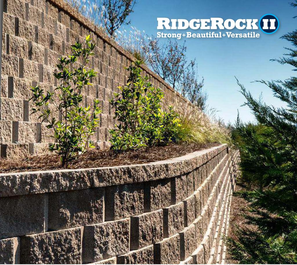
2 Strength & Versatility The RidgeRock II Retaining Wall System has the added advantages of smaller block size, lower costs, and easier installation. All of this with no compromise in structural stability, appearance or longevity. Remarkable Value & Superior Structural Integrity RidgeRock II is lighter weight, lower cost, and easier to install than other competitive products. Its superior shear mechanism, balanced center of gravity, and open-core design provide increased stability resulting in superior structural integrity. Integral Shear Key System The bottom of each RidgeRock II unit features a built-in concrete shear key that creates positive block-to-block shear. The user-friendly shear mechanism eliminates the need for separate pins or clips which can be easily forgotten or misplaced during the construction process. Flexible Wing Positioning System First introduced in the RidgeRock System, the Flexible Wing Positioning System (FWPS) provides greater lexibility in block positioning for easier installation of curved walls.the positioning wings, located on either side of the RidgeRock II units, deliver additional shear resistance between the integral shear key and the underlying course of blocks. Options in Appearance RidgeRock II is available in beveled face to offer increased shadowing effects or in straight face for clean lines. A variety of color options are available at most locations and vary by geographical region. Contact your local RidgeRock supplier for available options. Proven Product The irst choice of engineers, architects, municipalities and homeowners since 199, RidgeRock can be found in thousands of projects across the country. Now RidgeRock II follows in its predecessor s footsteps with the added advantages of smaller block size, lower costs, and easier installation, with no compromise in structural integrity. STRAIGHT UNIT Weight (empty) Setback per Course Approx. lbs. inches 1 inches 1.0 square ft. 1 inch* CAP UNIT BEVELED UNIT Weight Approx. 50 lbs. Weight (empty) Approx. lbs. inches inches 1 inches 1 inches 0.5 square ft. 1.0 square ft. Setback per Course 1 inch* Gray beveled block was used to allow building construction without encroaching into the stormwater pond. Beveled tan block allowed the entrance of this development to be constructed through a narrow easement.


3 Installation Steps STEP - Core and Drainage Fill Place ¾" to 1" clean aggregate within the cores, the area between blocks and a minimum of 1" behind the back of the blocks. Fill 1 block course at a time as wall construction proceeds. STEP 1 - Base Course Preparation Beginning at the point of lowest elevation, excavate a trench the length of the wall that will accommodate a minimum of of base material and of block embedment. As a rule of thumb for level areas, 1" of block should be embedded for every ft. of wall with a minimum of " embedded below grade. If your wall is placed on a slope, check with a local design engineer for requirements. The width of the trench should be a minimum of 1" and your trench depth will vary with wall embedment requirements. STEP - Leveling Pad Installation Place and compact a minimum of " of base material to 95% of Standard Proctor. Base material should consist of ¾" to 1" washed stone or crushed road base. This material will vary from region to region. STEP 3 - Base Course Installation Place the base course of block endto-end and use a string line along the back of the block to align straight walls. Center the blocks on the pad to allow a minimum of " of pad in front of and behind the blocks. Using a ft. level, level the blocks from side-to-side and front-to-back. Level across 3 full blocks to ensure level from block-to-block. Use a rubber mallet to seat the blocks into the leveling pad rather than attempting to push small amounts of material under the blocks. STEP 5 - Placement Level the drainage stone with the top of the block and ensure ill dirt has been placed and compacted to this same elevation. Clean all debris from the top of the block course. Cut the proper geogrid to the correct length and install with the strength direction of the geogrid perpendicular to the wall face. The strength direction is normally the roll direction, but check with the geogrid manufacturer for clariication. Extend geogrid to the front of the block. Place next course of RidgeRock II on wall in a running bond coniguration to hold geogrid in place. Pull geogrid taut from the back, removing any wrinkles. Pin or stake to hold in place while placing ill. Place and compact backill soils leaving 1" behind blocks for drainage ill. Place and compact drainage ill inside and 1" behind blocks. Straight face tan block gave the architect the look he desired for this common area focalpoint. STEP - Successive Course Installation Prior to adding successive courses, the block should be swept free of debris. Starting in the center of the wall, center the block in a running bond pattern and pull it forward until the Shear Key engages the positioning wings. Place backill material in maximum 1" loose lifts and compact to 95% of standard proctor leaving 1" of space behind the block for drainage ill. Place drainage ill behind and in blocks one course at a time and compact. Only hand operated compaction equipment such as a vibrating plate compactor should be used within 3 ft. of the back of the block. Continue with successive courses placing geogrid as required by design until full height is reached. STEP 7 - Capping the Wall Top caps are generally " in height and should be placed with the split edge forward. Adhere top caps with construction adhesive speciically manufactured for masonry use. Cap styles may vary by region. Check with your local representative for options.. STEP - Top of Wall Stepping Where steps must occur in the top of the wall to follow inished grades, double capping at each step can be used to provide a inished appearance. Installation Notes These installation steps are applicable to most situations. However, special design considerations must be given in some instances to ensure hydrostatic forces do not develop and that conditions behind of and in front of the wall are handled correctly. These instances include but are not limited to ponding water, sloping grades, surcharge conditions, fences and guardrails, tiered walls, driveways and roads, groundwater, culverts, bridges, drainage structures and streams or creeks. Beveled face natural gray was chosen to increase the usable space for apartment buildings.
 '-0\" (3 block courses) Case 1 Reinforced Walls Case 50 PSF Surcharge length (L) E Corner Details CONSTRUCTION Split with")

 E- E- E- \" Min.")
4 Details & Charts Gravity Walls Reinforced Wall Detail 9" Maximim Unreinforced Wall 7.1 Batter " Cap unit 1" 7.1o Soil Type Level ill 3H:1V Slope Sand/Gravel* Ф=3 '-" ( block courses) '-0" (3 block courses) Case 1 Reinforced Walls Case 50 PSF Surcharge length (L) E Corner Details CONSTRUCTION Split with chisel and hammer E E E E Drainage material ( 3"- 1" Crushed stone) *See note. Reinforced soil Lower course Successive course " Min. " Dia. perforated drain pipe Base leveling pad 1" Min. Note: Prefabricated corner units may also be available in some locations * Embedment below grade varies with *Embedment below grade with wall with a "varies minumum. condition in front of Radius Details 9" Option A No block modifications required Radius = '-9" " Cap unit 1" Varies Elevations (Feet above base) E- E- E- " Min Option B Remove wings and bottom lug Radius = 1'-7" Note: Radii shown are measured at top of wall. Radii at bottom of wall will need to be increased to account for wall batter Interlocking back view of RidgeRock II blocks shown below Elevations (Feet above base) E- E- E- Case 3, H:1V sloping ill Elevations (Feet above base) E- E- E Elevations (Feet above base) E- E- E- Case, Level ill, 50 psf surcharge It is assumed that wall construction is in accordance with RidgeRock speciications and industry standards. All backill soils are assumed compacted to 95% of standard proctor and placed in maximum " compacted lifts. Base leveling pad 1" Min. Our patented Flexible Wing Positioning System, shown in this photo, allows for quick and accurate positioning of each unit. charts are applicable only to soils possessing an angle of internal friction (PHI) of, 30 and 3 and a moist unit weight of lbs./cu.ft. For other soil types consult a local design engineer. Backfill soil " Dia. perforated drain pipe Assumptions & Notes 7.1o ( 3"- 1" Crushed stone) Case 3, 3H:1V sloping ill Unreinforced Gravity Wall Detail Drainage material Elevations (Feet above base) E- E- E- Silty Sand: Ф=30 Y= pcf Case, Level ill, 50 psf surcharge Saw cut E length (L) Silt/ Lean Clay: Ф= Y= pcf Varies 3 ft. reinforcement Sloping Fill length (L) *See design assumption notes Case 3 50 PSF Surcharge Level Grade Level Grade No Surcharge Gravity wall calculations assume no surcharges are located within a distance of two times the wall height behind the wall. Gravity wall calculations assume the use of free draining ¾" to 1" stone for the leveling pad and within a horizontal distance of one-half of the wall height behind the back of the block. The geogrid charts are based on a standard block unit setback of 1" per course. lengths shown are measured from the face of the block to the tails of the geogrid. Wall heights shown in the design charts are measured from the top of the leveling pad to the top of the top-most " block course. charts provide geogrid requirements in ft. wall height increments. Judgment will be required when interpolating between these heights. charts are based on the use of GridLok 70 coated polyester geogrid with a design strength (LTDS) of 175 lb/ft. per the NCMA Manual for Segmental Retaining Walls, 3rd Edition. Information on other speciic geogrid is available through the geogrid manufacturer. Information provided in the design charts is for informational purposes only. A qualiied engineer should be consulted for inal wall design purposes. RidgeRock Retaining Walls, Inc. accepts no liability for the use of these charts or any results thereof. Elevations (Feet above base) E- E- E- Sand/Gravel: Ф=3 Y= pcf Elevations (Feet above base) E- E- E- Case, Level ill, 50 psf surcharge Elevations (Feet above base) E- E- E- Case 3, H:1V sloping ill Elevations (Feet above base) E- E- E-


5 The RidgeRock Family RidgeRock II RidgeRock II s smaller block size features the same structural stability, design lexibility and Flexible Wing Positioning System as its larger RidgeRock predecessor. A technological breakthrough, RidgeRock II s smaller format results in lower costs and easier installation. RidgeRock The RidgeRock Retaining Wall System is the premier choice in soil retention technology. The RidgeRock unit is stabilized with a user-friendly concrete shear key which is integrated into the block to avoid the need for pins or clips