RESEARCH PROJECT AT UNIVERSITY OF NEVADA, RENO
|
|
|
- Randolph Lewis
- 5 years ago
- Views:
Transcription


1 RESEARCH PROJECT AT UNIVERSITY OF NEVADA, RENO QUARTERLY REPORT July 1, 2017 to September 30, 2017 Period Year 2 Project Shake Table Studies of a Bridge System with ABC Connections Submitted by M. Saiidi, A. Itani, M. Moustafa, and E. Shoushtari Department of Civil and Environmental Engineering University of Nevada, Reno Reno, Nevada Submitted October 2017
2 TABLE OF CONTENTS A. Description of Research Project... 3 A.1 Problem Statement... 3 A.2 Contribution to Expanding Use of ABC in Practice... 5 A.3 Research Approach and Methods... 5 A.4 Description of Tasks to Be Completed in Research Project... 6 Task 1- Literature Review... 6 Task 2- Evaluate ABC Connections in Details... 6 Task 3- Develop preliminary design for a two-span large-scale bridge model for shake table testing... 8 Task 4- Finalize bridge model details, construct and instrument the bridge model, and conduct shake table tests Task 5 Process and interpret shake table test data and assess seismic performance of bridge model Task 6 Conduct analytical studies of the bridge model Task 7 Summarize the investigation and the results in a draft final report A.5 Expected Results and Specific Deliverables
3 Year 2 Project: Shake Table Studies of a Bridge System with ABC Connections UNR Project Website: ABC-UTC Project Website: >>> ABC-UTC Webmaster please update <<<<<< A. Description of Research Project ABC connections for prefabricated members are particularly critical in moderate and high seismic zones because earthquake forces place high demand on inelastic deformation of adjoining columns. Structural integrity of the bridge has to be maintained by capacity-protected connections that experience no or little damage. Various ABC connections have been developed and investigated in the past few years. Because of the critical role of bridge columns, the majority of these connections for column ends at foundation and cap beams. In addition to column connections, superstructure to pier cap connections are also important to ensure that no plastic deformations are developed within the superstructure. Five types of ABC column connections have been developed [Ref. 1-57], each with a variety of details: 1. Grouted Duct (GD) Connections 2. Mechanical Bar Splices 3. Pocket Connections 4. Pipe Pin Connections 5. Rebar Hinge Connections 3
4 Superstructure precast concrete or steel girder to pier cap seismic connections are also of different types and details depending on the type of girder (steel or concrete) and the mechanism to provide positive moment capacity at the superstructure cap beam interface. Except for studies in Ref. 26 and 62, all the other reported studies on ABC connections have been on components consisting of single or a subassembly of part of bridges. Component studies have been essential in understanding the local behavior of connections and have provided invaluable information that is beginning to help formulate seismic design guidelines for ABC connections. However, important questions remain on the total bridge seismic response when these connections are integrated in a bridge system. For example, it is not known how simple for dead, continuous for live (SDCL) connections behave under seismic loading when the girders are integrated with precast cap beams and column pocket connections. The studies in Ref. 26 and 62 are on innovative concepts using advanced materials that are still emerging. Those studies do not directly address conventional reinforced concrete or steel materials and details. There are three reasons for the lack of data on the seismic response of conventional ABC bridge systems: (1) It has been essential to develop an understanding of ABC connection behavior at the component level before system studies can be undertaken, (2) seismic studies of bridge systems requires unique distributed shake table systems with sufficient capacity to test large-scale bridge models, and (3) bridge system tests are costly because of the number of components involved and the associated labor and laboratory fee costs. The second barrier is addressed by the state-of-the-art shake table testing facility at UNR. The issue of cost can be addressed through allocating a portion of the ABC-UTC funds. 4
5 The purpose of the study proposed at UNR using the ABC-UTC funds is to integrate various ABC column and superstructure connections in shake table studies of a large-scale bridge model. A.2 Contribution to Expanding Use of ABC in Practice Because satisfactory seismic performance of bridges cannot be guaranteed unless the connections are sound and reliable, states in moderate and high seismic zones have viewed substantial research data on ABC connections as an essential prerequisite before ABC can be embraced. Plausible earthquake-resistant precast component connections have been developed and preliminary design guidelines are emerging. However, a holistic study of ABC bridge system and the effect of interaction and load distribution among bridge components is necessary before bridges with ABC connections can be confidently recommended for adoption in routine bridge design and construction in states that are susceptible to earthquakes. Incorporation of steel girders in this study will generate information and could help expand the options available to bridge designers in moderate and strong seismic zones. A.3 Research Approach and Methods The overall objective of the proposed study is to investigate the seismic performance of a large-scale two-span bridge system that integrates some of the more promising ABC connections that have been proof tested. The selection of the connections will be based on the latest state-ofthe-art review, a recently developed evaluation document [63], feedback from other ABC-UTC researches, the ABC-UTC-Seismic steering committee, and the AASHTO T-3 committee. A two-span bridge model with concrete substructure, steel girders, and precast deck panels is envisioned. The bridge model will be supported on three shake tables at UNR and will be 5
6 subjected to bidirectional horizontal seismic loading. Representative earthquake records will be simulated at the pier base and the abutments. The model will be tested under seismic loading of increasing amplitude until failure. Different limit states including the ultimate condition will be investigated. Specific objectives of the project are to determine: a) Any constructability issues related to assembling various bridge components and connections, b) interaction among different bridge components, c) effect of combined gravity and bidirectional seismic loading on ABC connections, the effectiveness of CFRP tendons in minimizing residual displacements under strong earthquakes, and d) adequacy of emerging seismic design guidelines for ABC connections. study: A.4 Description of Tasks to Be Completed in Research Project The proposed research will consist of the following tasks to accomplish the objectives of the Task 1 Literature Review 100% Completed An in-depth literature search is conducted to identify the most recent test data and analytical results on cyclic load or dynamic load studies of prefabricated bridge elements and their connections. The search includes any tests or analyses of ABC bridge systems subjected to seismic loading. Included is precast deck panels and their connections to girders and to other panels. 6
7 Under Task 1 of the study, the literature search is updated and expanded to identify any new information that could potentially enhance the menu of different earthquake-resistant ABC elements and connections. Task 2 Evaluate ABC connections and details 100% completed The catalog of prefabricated elements and ABC connections is prepared and a rating system is developed to help identify optimum ABC details that factor in seismic performance, ease of construction, time saving, cost, durability, damage susceptibility, etc. For example, prefabricated columns may be solid, segmental, hollow, SCC (self-consolidating concrete) filled hollow columns, concrete-filled steel tubes, concrete-filled FRP (fiber-reinforced polymer) tubes, etc. The relative merit of these alternatives is evaluated. Another example is connection between columns and cap beams. Grouted ducts and pocket connections are among some of the most investigated connections. Another alternative adopted by some states involve the use of mechanical splices. These and any other emerging alternatives are assessed and pros and cons of each are identified. A few alternative SDCL connections under seismic loading have been developed. Relative merit of these connections is evaluated. Past research on SDCL connections for steel girders under seismic loading are limited but current research at the Florida International University could yield practical alternative connections. These details are assessed in collaboration with FIU researchers because one of the main objectives of this research is to study the seismic performance of SDCL connection detail at FIU Phase I of the FIU work aimed at developing a detail that is suited for seismic application. Phase II of the FIU study includes a component testing of the seismic SDCL detail, before incorporating the connection in the shake table test model. UNR and FIU researcher will maintain close cooperation during the project. 7
8 Task 3 Develop preliminary design for a two-span large-scale bridge model for shake table testing: 100% Completed Select ABC connection details and prefabricated elements that are ranked at the top of different alternatives are integrated in a, 0.35-scale, straight, two-span bridge models to be tested on the UNR shake tables. The preliminary dimensions of the assumed prototype are shown in Fig. 37. The width and the number of the girders of the bridge are approximately 80% of a bridge for a two-lane highway bridge. The width was reduced to allow for a larger scale of the bridge model. The details in Fig. 37 are preliminary and conceptual at this stage. Preliminary design of the steel girders, the columns, the cap beam, and the deck has begun. All the components will be precast elements except for the portion of the girder to cap beam connection detail that will utilize FIU s SDCL connection detail that requires closure pours. The key details to be decided are column connection to the footing, column-pier cap connection, girder-cap beam connection, deck-girder connection, and connections between adjacent decks. The preliminary shake table test setup is shown in Fig ' 100' 4' 20' 4' 31' 18' 20' 4' 8" Fig. 37- Preliminary configuration of the prototype 8
9 W E 11' 35' 35' 11' Strong Wall Abut. 1 Bent 2 Abut. 3 Fig. 38- Plan view of the preliminary test setup The preliminary design of the steel superstructure utilizing four steel girders was carried out. Figure 39 shows the details of the steel girders. The girders include welded studs for connection of precast deck panels that are being designed. The cross frame location are marked in the figure. Details of the cross frames are shown in Figure 40. A request was made to the National Steel Bridge Alliance in July for donation of the steel components for the superstructure. Based on discussion between the Director of ABC-UTC and NSBA, the girders, cross frames, and other accessories are to be donated to UNR. 9

10 Fig. 39 Details of superstructure steel plate girders. 10


 to donate the steel")
11 Fig. 40 Details of superstructure cross frames Task 4 Finalize bridge model details, construct and instrument the bridge model, and conduct shake table tests 38% Completed The design of the bridge model was completed, and the testing configuration was finalized. The abutment actuators shown in Fig. 38 were eliminated because further detailed nonlinear analysis revealed that they are not necessary for failure testing of the bridge model. With assistance from FIU, a request was submitted to the National Steel Bridge Alliance (NSBA) to donate the steel girders and other superstructure steel components. NSBA has agreed to provide the material to the Reno Iron Work (RIW) for fabrication. NSBA has partially 11


12 covered the cost of fabrication. The remainder of the fabrication costs are born by the UNR- ABC-UTC budget and donation by RIW. Construction of the two-column bent began. Figures show reinforcement or formwork for different components of the pier model. Strain gage layout was finalized and the gages were ordered and received. They have been installed on select rebars in critical parts of the components. Fig. 41 Formwork for the precast portion of cap beam Fog Footing reinforcement 12


13 Fig. 43 Column reinforcement cages Fig. 44 Cap beam reinforcement cage Figure 45 shows the completed footing for the pier. The sockets left in the footing are for column-footing connections. The completed precast columns are shown in Fig. 46. The reduced end bars are two-way hinges that will be inserted into the footing sockets and grouted. The bars at the other end of the columns will be inserted into the grouted ducts in the lower part of the cap beam and extended into the cast-in-place part of the upper part of the cap beam. Figure 47 shows the completed lower part of the cap beam. The holes in the beam indicate the grouted 13

. Fig.")
14 ducts, and the reinforcement extending out of the cap beam are the bars to help complete the remainder of the cap beam. Fig. 45- Precast footing with sockets (pockets). Fig. 46- Completed precast columns for the bent 14

15 Fig. 47- Completed lower cap beam with corrugated ducts The design of the deck panel was finalized and a construction bid was obtained. The layout of the deck panels in the vicinity of the pier is shown in Fig. 48. Another activity of the project is securing donation of steel from the National Steel Bridge Alliance, identification of a local steel fabricator, and fabrication of the steel girders and the diaphragm. Figure 39 shows the details of the steel elements of the superstructure. The construction of the precast deck panels began during the last period and was completed during this period. Figure 49 shows an over view of the deck panel reinforcement and Fig. 50 shows the completed deck panels for one of the spans. The steel reinforcement in the end deck panels in each span extend out to be connected to the SDCL connection at cap beam. Figure 51 shows the extended bars. 15


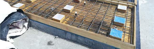
16 Fig. 48 Deck panel layout Fig. 49 Deck panel steel reinforcement 16


17 Fig. 50 Completed deck panels for one of the spans Fig. 51 Edge deck panel with extended reinforcement on the right The steel plate girders were fabricated during this period. Figure 52 shows the welding of the flanges and the web. Attaching the studs to be inserted in the precast deck panel pockets is shown in Fig. 53. The girder end details were also completed. Figure 54 shows the ends that are to be connected to the SDCL connection at the pier. The holes in the web allow for passage of transverse reinforcement. The steel girders were delivered during this period. The cross braces were attached as shown in Fig


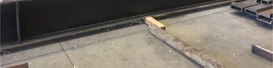
18 Fig. 52 Welding of the flanges to the web Fig. 53 Attachment of studs 18


19 Fig. 54 Girder end details for SDCL connection at cap beam Fig. 55 Assembled girders with cross braces 19
20 Task 5 Process and interpret shake table test data and assess seismic performance of bridge model Pending Task 6 Conduct analytical studies of the bridge model Pending Task 7 Summarize the investigation and the results in final report Pending A.5 Expected Results and Specific Deliverables The deliverables from different tasks are as follows: Task 1: A synthesis of the literature review providing a summary of the state-of-the-art on seismic performance of different prefabricated bridge components and connections. Task 2: A summary of optimum ABC connections and prefabricated elements with a ranking system. Task 3: Preliminary plans and dimensions of a 2-span bridge model with connection details at all the joints in addition to the rationale for selection of the prefabricated elements and connections. Task 4: Finalized plans and details for a 2-span bridge models in addition to instrumentation plans and the earthquake simulation protocol. Task 5: Key processed data and interpretation of data that are indicative of the bridge seismic performance at the system and component levels in addition to video clips of bridge and connection movements and photos of damage progression at different locations of the bridge models. 20
21 Task 6: A reliable analytical modeling method for inelastic seismic analysis of ABC bridge systems. Task 7: A report summarizing the key steps and procedures used in the study in addition to the data on seismic performance of the bridge model and the related analytical study results. Conclusions regarding component versus system performance of different components, interaction among different components, and variation of load path under different limit states. 21