Cladding Attachment Through Exterior Insulation Using Long Screws PHIUS 10 TH ANNUAL NAPHC, CHICAGO COLIN SHANE M.ENG, P.ENG 11 SEPTEMBER 2015
|
|
|
- Andrea Fleming
- 5 years ago
- Views:
Transcription


1 Cladding Attachment Through Exterior Insulation Using Long Screws PHIUS 10 TH ANNUAL NAPHC, CHICAGO COLIN SHANE M.ENG, P.ENG 11 SEPTEMBER 2015
2 Learning Objectives / Overview Understand of the impacts of thermal bridging from cladding attachments on thermal performance of wall assemblies Review multiple types of cladding attachment systems and their effective thermal resistance Learn about cladding attachment with discrete fasteners through exterior insulation, including discussion of thermal efficiency, air and water tightness, and structural resistance Review several case studies to understand practicality of discrete cladding attachment with long screws
3

4 Building Enclosure Design Fundamentals Control of exterior moisture/rainwater & detailing Thermal insulation continuity & effectiveness Airflow control/airtightness Control of condensation and vapor diffusion More insulation = less heat flow to dry out moisture Amount, type and placement of insulations matters, for vapor, air and moisture control Greater need to more robust and better detailed assemblies

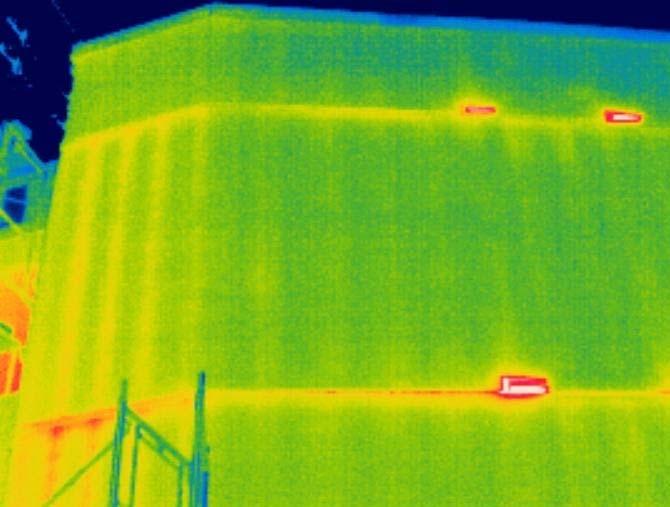
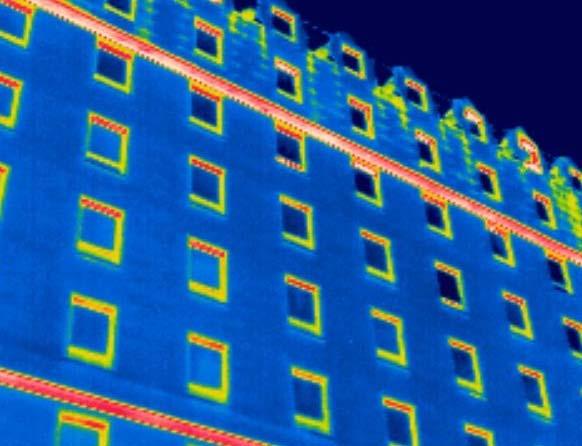
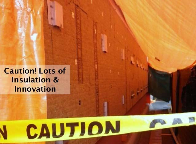
5 What do you See?

6 What do you See?
 bypasses a less conductive material (insulation) Minimizing thermal bridging is key to passive building design Use of exterior")

7 Thermal Bridging Thermal bridging occurs when a more conductive material (e.g. metal, concrete, wood etc.) bypasses a less conductive material (insulation) Minimizing thermal bridging is key to passive building design Use of exterior continuous insulation with thermally improved cladding attachments Minimizing the big thermal bridges Have historically focused on assembly R-values, however more attention is now being placed on interface and detail R-values, and cladding attachments Address the weakest links first


8 Getting to Higher R-values - Walls Traditional 2x6 w/ R-22 batts = R-16 effective Exterior Insulation: R-20 to R-60+ effective Constraints: cladding attachment, wall thickness Good for wood/steel/concrete Deep/Double Stud: R-20 to R-40+ effective Constraints: wall thickness Good for wood, wasted for steel Split Insulation: R-20 to R-60+ effective Constraints: cladding attachment Good for wood, palatable for steel

9 Building Enclosure & Passive Design Building enclosure is key element in passive design Exterior insulation is only as good as the cladding attachment strategy What attachment system works best thermally? Need to also consider: Structural Air / water tightness Constructibility

10 Many Cladding Attachment Options & Counting

11 Vertical & Horizontal Continuous Z-Girts

12 Intermittent Metal Clips - Better


13 Thermally Improved Clip & Rail Systems

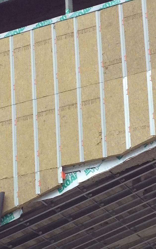
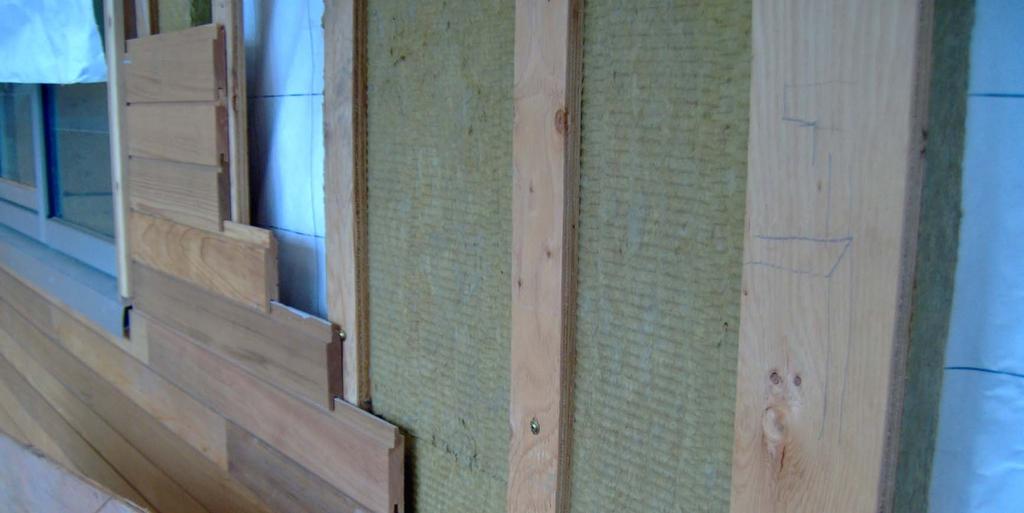
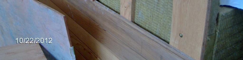
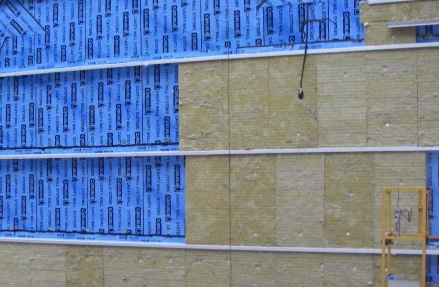
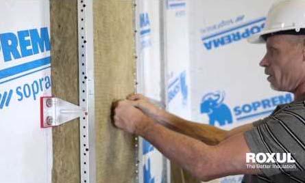
14 Screws Through Insulation Layer
 Cladding Attachment System R-4.")


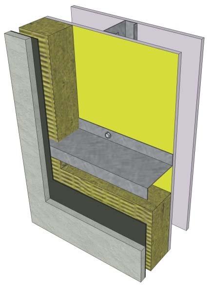
15 Thermal FE Modelling Exterior Fiber Cement Board Cladding 3/4 Air Space (Rainscreen) Cladding Attachment System R-4.2/in Exterior MW Insulation Plywood Sheathing 2x6 Wood 16 OC with R-22 Batt Insulation Interior Gypsum Interior Exterior Fiber Cement Board Cladding 3/4 Air Space (Rainscreen) Cladding Attachment System R-4.2/in Exterior MW Insulation Gypsum Sheathing 3 5/8 Steel 16 OC with R-12 Batt Insulation Interior Gypsum Interior
16 Thermal Results Insulated Wood Frame Wall Effective R-Value of Whole Wall Assembly (ft 2 F hr/btu) Effective R-Value NO PENETRATIONS NO PENETRATIONS NO PENETRATIONS Nominal R-Value of Exterior Insulation (ft 2 F hr/btu) Continuous Vertical Z-Girt - 16" OC Continuous Horizontal Z-Girt - 24" OC Aluminium T-Clip - 16" x 48" Aluminium T-Clip - 16" x 24" Intermittent Galvanized Z-Girt - 16" x 48" Intermittent Galvanized Z-Girt - 16"x 24" Isolated Galvanized Clip - 16" x 48" Isolated Galvanized Clip - 16" x 24" Intermittent SS Z-Girt - 16" 48" Intermittent SS Z-Girt - 16" x 24" Fiberglass Clip - 16" x 48" Fiberglass Clip - 16" x 24" Galvanized Screws - 16" x 16" Galvanized Screws - 16" x 12" SS Screws - 16" x 16" SS Screws - 16" x 12"
17 Thermal Results Insulated Wood Frame Wall Percent Thermal Degredation of Exterior Insulation 80% 60% 40% 20% 0% Percent Thermal Degradation Nominal R-Value Nominal of R-Value Exterior of Insulation (ft 2 F hr/btu) (ft 2 F hr/btu) Continuous Vertical Z-Girt - 16" OC Continuous Horizontal Z-Girt - 24" OC Aluminium T-Clip - 16" x 48" Aluminium T-Clip - 16" x 24" Intermittent Galvanized Z-Girt - 16" x 48" Intermittent Galvanized Z-Girt - 16"x 24" Isolated Galvanized Clip - 16" x 48" Isolated Galvanized Clip - 16" x 24" Intermittent SS Z-Girt - 16" 48" Intermittent SS Z-Girt - 16" x 24" Fiberglass Clip - 16" x 48" Fiberglass Clip - 16" x 24" Galvanized Screws - 16" x 16" Galvanized Screws - 16" x 12" SS Screws - 16" x 16" SS Screws - 16" x 12"
18 Thermal Results Insulated Steel Stud Wall Effective R-Value of Whole Wall Assembly (ft 2 F hr/btu) Effective R-Value NO PENETRATIONS NO PENETRATIONS Nominal R-Value of Exterior Insulation (ft 2 F hr/btu) NO PENETRATIONS Continuous Vertical Z-Girt - 16" OC Continuous Horizontal Z-Girt - 24" OC Aluminium T-Clip - 16" x 48" Aluminium T-Clip - 16" x 24" Intermittent Galvanized Z-Girt - 16" x 48" Intermittent Galvanized Z-Girt - 16"x 24" Isolated Galvanized Clip - 16" x 48" Isolated Galvanized Clip - 16" x 24" Intermittent SS Z-Girt - 16" 48" Intermittent SS Z-Girt - 16" x 24" Fiberglass Clip - 16" x 48" Fiberglass Clip - 16" x 24" Galvanized Screws - 16" x 16" Galvanized Screws - 16" x 12" SS Screws - 16" x 16" SS Screws - 16" x 12"
19 Thermal Results Insulated Steel Stud Wall Percent Thermal Degredation of Exterior Insulation 100% 80% 60% 40% 20% 0% Percent Thermal Degradation Nominal R-Value of Exterior Insulation (ft 2 F hr/btu) Continuous Vertical Z-Girt - 16" OC Continuous Horizontal Z-Girt - 24" OC Aluminium T-Clip - 16" x 48" Aluminium T-Clip - 16" x 24" Intermittent Galvanized Z-Girt - 16" x 48" Intermittent Galvanized Z-Girt - 16"x 24" Isolated Galvanized Clip - 16" x 48" Isolated Galvanized Clip - 16" x 24" Intermittent SS Z-Girt - 16" 48" Intermittent SS Z-Girt - 16" x 24" Fiberglass Clip - 16" x 48" Fiberglass Clip - 16" x 24" Galvanized Screws - 16" x 16" Galvanized Screws - 16" x 12" SS Screws - 16" x 16" SS Screws - 16" x 12"

20 Common Concerns Air and Water Penetration I spent all this time making my air and water barrier perfect, and now I m going to turn it into Swiss cheese! How much does this matter? Historically with continuous girts not a lot With only screws?
 fasten")
 Qualitative testing of water and air leakage Fluorescent")
21 Procedure Test the self-sealing ability of membranes around screw and nail (insulation pin) fasteners (i.e. represent cladding attachment & insulation retaining fasteners used in exterior insulated walls) Qualitative testing of water and air leakage Fluorescent dye used to identify water leakage Theatrical smoke used to identify air leakage

22 Test Wall and Test Chamber Insulated Wall types 1. Steel stud + Densglass with liquid AB 2. Steel stud + Densglass with SAM Interior and exterior views of test chamber
23 Test Setup 1 Air Leakage CFH = 3 CFH Wall assembly 100Pa 40Pa 10Pa 30Pa 20Pa 60Pa 50Pa 70Pa 80Pa 90Pa 2 Smoke 3 Water Penetration Test Chamber
24 Impact of Fasteners on Membrane Airtightness? Impact of Exterior Insulation Fasteners on the Airtightness of Liquid & Self-Adhered Membranes cfm/ft Pa Maximum allowable air leakage rate for air-barrier material Negligible 0 CMU - self-adhered membrane - Insulfast CMU - liquid applied membrane - Insulfast Steel stud - self-adhered membrane - InsulFast Steel stud - liquid applied membrane - Insulfast CMU - self-adhered membrane - Screws CMU - liquid applied membrane - Screws Steel Stud - self-adhered membrane - Screws Steel stud - liquid applied membrane - Screws
 700 Pascals (14.")
25 Insulated Walls - Water Penetration ASTM E1105 Test Conditions 0 Pascals 200 Pascals (4.8 psf) 700 Pascals (14.6 psf) 700 Pascals (insulation removed)

26 Water Penetration Steel stud with SAM 1 location
27 Air Barrier Conclusions Airtightness of adhered/liquid membranes is negligibly impacted by fasteners into structure or even misfired (as long as left in place) Net impact is well below cfm/ft 75Pa target (typically in cfm/ft 2 range)
28 WRB Conclusions Water tightness not practically impacted Some fasteners could leak where membrane exposed to full ASTM E1105 water load applied to WRB Not a real world scenario (why we clad) Cladding buffers 95% water, insulation buffers remaining 4%, possibly 1% getting behind/through insulation No anecdotal evidence to suggest a problem Thickness and self-sealing of WRB/AB membrane matters here

29 Common Concerns - Structural
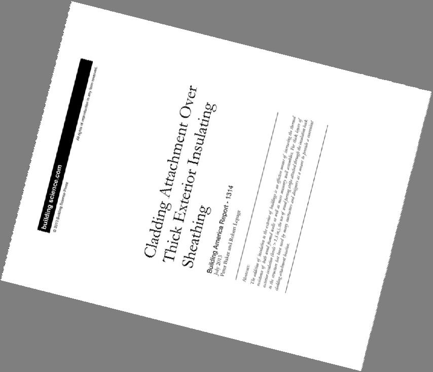

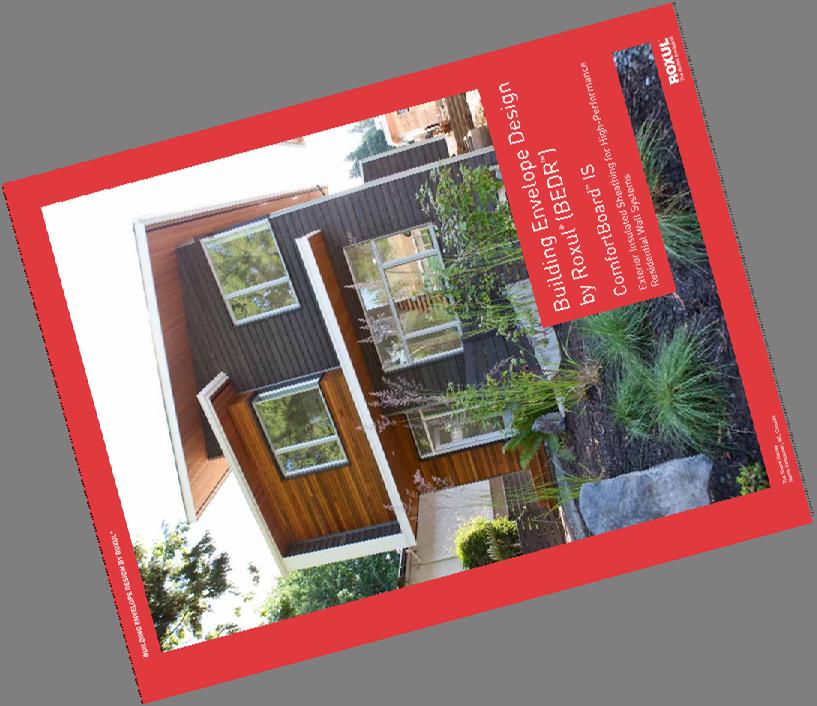

30 Publications / Research Reports And many others!


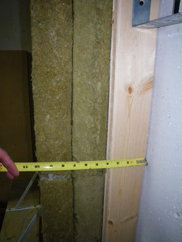
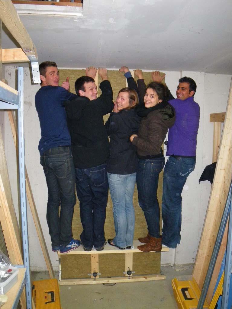
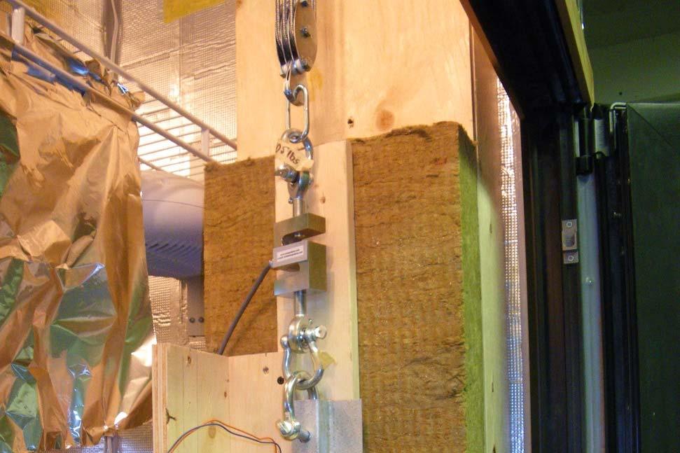
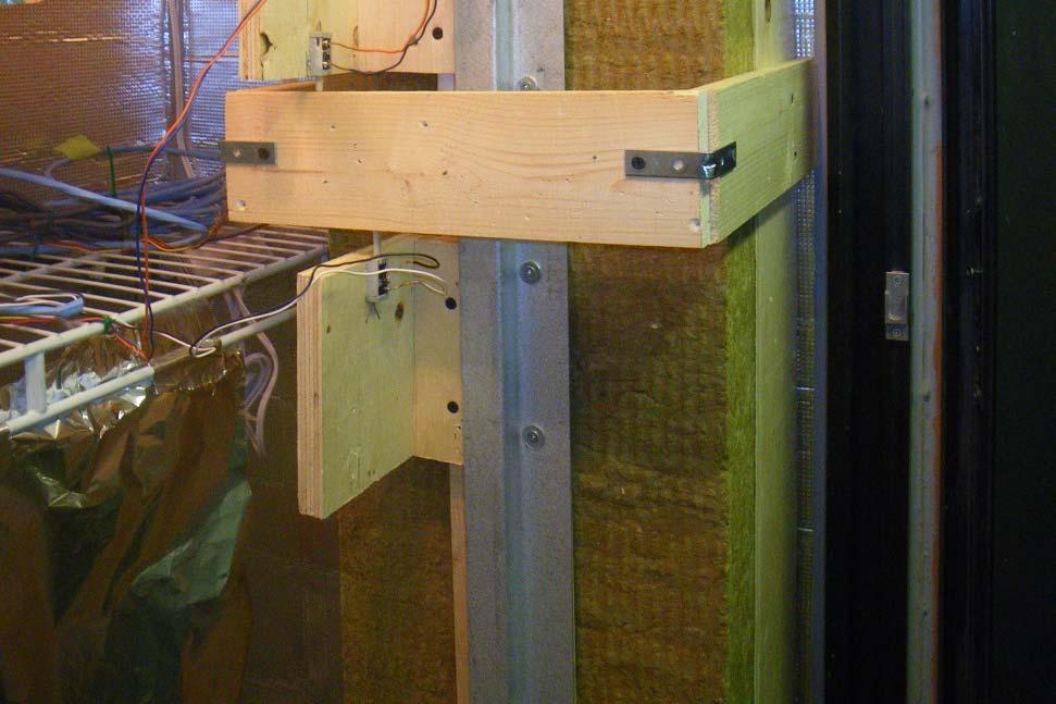
31 Lab Examples and Testing ± 25 psf


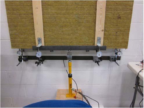

32 Lab Examples and Testing


33 Some Context on Load Values How heavy is cladding? Vinyl siding 2 psf Fiber cement 5 psf Cement plaster 10 psf Stone veneer 25 psf Brick 40 psf Typical Example 16 inches x 16 inches screw spacing Fiber Cement 9 lbs per screw Very small forces for many typical arrangements
34 Resisting Vertical Loads - Screw Bending Screw bending resistance easy to calculate from established calculation methods ASTM F1575 Standard Test Method for Determining Bending Yield Moment of Nails For small insulation thickness (< 2 in) and lightweight cladding (< 5 psf), screw bending generally sufficient to resist cladding loads alone - conservative

35 Resisting Vertical Loads the Effect of Strapping Strapping compresses insulation layer, creating friction Often ignored for design purposes, but research has shown it can provide significant resistance Over 20 lbs of vertical resistance per fastener has been reported Strapping required to develop strut and tie forces Strap compresses insulation as cladding deflects downward Resulting tension resisted by screws

36 Still Not Convinced Use Shear Blocks With heavy or brittle claddings may consider shear blocks to limit deflection and creep Not necessary with light-weight claddings Shear block material: Continuous or intermitted wood blocks, metal clips, clip and rail system, etc.


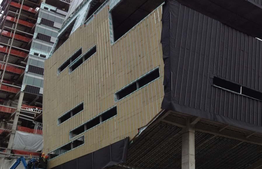
37 Current Passive House Project Modular construction for a remote site in a cold climate Highly insulated walls with screws through 6 inches of exterior insulation
38 Discussion + Questions rdhbe.com