Using BrR To Evaluate Bascule Bridges
|
|
|
- Abraham Hubbard
- 5 years ago
- Views:
Transcription

 ckois@collinsengr.")
1 Using BrR To Evaluate Bascule Bridges 2018 RADBUG MEETING BOISE, IDAHO AUGUST 7 8, 2018 Presenters: Carolyn Kois, PE (Collins Engineers, Inc.) ckois@collinsengr.com Jim Surber, PE, SE (Alfred Benesch & Co.) jsurber@benesch.com
2 Using BrR To Evaluate Bascule Bridges Summary of Presentation Background on CDOT & CBIT LaSalle St. and Lake St. Bascule Bridges Carolyn Kois, P.E. Roosevelt Rd. and Cermak Rd. Bascule Bridges Jim Surber, P.E, S.E.


3 Five Bridge Types Maintained by 43 15% % 41 15% Fixed Bridges Movable Bridges Pedestrian Bridges Three Sided Frames Viaducts Total = % 43 16%


4 Chicago Bascule Bridges

5 Chicago Bascule Bridges


6 Who is CBIT? Chicago Bridge Inspection Team A Joint Venture Teaming of Alfred Benesch & Company and Collins Engineers, Inc.


7 Bridge Inspections Routine, Special, Fracture Critical, Underwater and Element Level Mechanical and Electrical of movable bridges NDT including UT testing Confined spaces Rope access, barges and man lifts On Call Engineering Services Bridge repairs Emergency services Bascule bridge balancing Load Rating

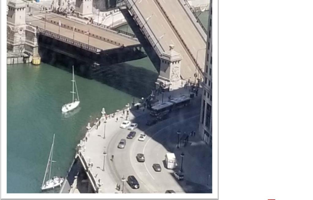
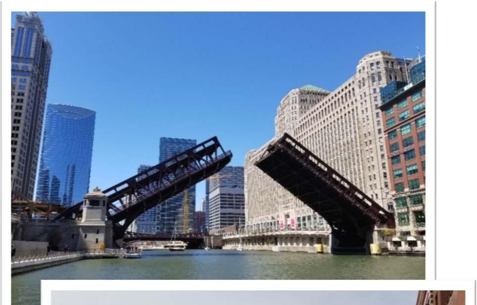
8 LaSalle St. Bascule Single Level Double Leaf Trunnion Type Bascule
9 LaSalle St. Bascule Bascule Components and Supports

10 LaSalle St. Bascule Original Construction Construction/Repair History 1928 Original Construction 1969 Timber Deck Replaced with Steel/Concrete Deck rebalancing of counterweight Design Load Geometry between live load bearings 11 6 live load bearings to trunnions 35 3 trunnions to anchor columns

11 LaSalle St. Bascule Carrying Elements Fixed span elements mostly rated in BrR Supplemental analysis required outside of BrR for some carrying elements

12 LaSalle St. Bascule Dead Load Forces Dead Loads Truss member self weight Floorbeams Stringers Cantilever sidewalks Lateral Bracing Deck Counterweight Steel Grating Deck with Concrete Infill at Centerlock and Floorbreaks Non composite deck Deck thickness/weight adjusted to reflect weight of open steel grating Additional weight of concrete fill applied as distributed loads
13 LaSalle St. Bascule Dead Load Balancing Balanced Condition Counterweight for DL model based on design and rehab plans Bascules rebalanced after repairs/alterations/maintenance Reaction at live load bearing is calculated for balanced condition (slightly noseheavy) Counterweight is verified by comparing DL reaction at LL bearing reaction based on plan weight to LL bearing reaction calculated for balanced condition
14 LaSalle St. Bascule Load Stages Dead Load: supported by trunnion only (with minimal DL at LL bearing when bridge is closed) Live Load: supported by trunnion, LL bearing & anchor column (with shear transfer at centerlock) Half deck line locations in BrR set to reflect the loaded panel points for live load Pedestrian load included with live load

15 LaSalle St. Bascule Live Load Vehicle and Pedestrian Load Supports Pin Support at Trunnion Roller Support at LL Bearing Roller Support at CW Bumper Centerlock Centerlock transfers shear Does not transfer moment or axial load)
16 LaSalle St. Bascule Verification of Dead Load Support Conditions Location Top Chord Bottom Chord Verticals Design Stress Sheet DL (k) AASHTOWare Member STAAD DL balance model (no centerlock or heel lock) Location Diagonals Rear Members Design Stress Sheet DL (k) AASHTOWare Member STAAD DL balance model (no centerlock or heel lock) a a a Note: Numerous structure components, including the deck, have been modified since original construction. Original dead load forces are provided for information, however the dead load used for analysis was calculated based on the current structure geometry.


17 LaSalle St. Bascule Load Rating Analysis Floorbeams and Stringers Moveable portion modeled in BrR in truss superstructure definition Fixed spans modeled in BrR as separate superstructure alternative Note: BrR does not model simple span floorbeams when there are more than 2 truss lines in a bridge. Floorbeams are analyzed as continuous so workaround is required to model them as simple span between trusses.

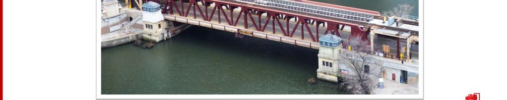
18 Lake St. Bascule Double Level Double Leaf Trunnion Type Bascule

19 Lake St. Bascule Original Construction Construction/Repair History 1914 Original Construction 1994 lower level floor system replacement and rebalancing of counterweight Various other repairs over the history of the bridge Geometry between live load bearings 14 0 live load bearings to trunnions 37 7 trunnions to heel locks Design Load HS 20 Design Live Load for Lower Level Floor System constructed in 1994 to replace original lower level framing
20 Lake St. Bascule Load Stages Dead Load: supported by trunnion (minimal DL reaction at LL bearing for balanced condition) Live Load: supported by trunnion, LL bearing & heel lock Live Load: shear transfer at centerlock) 2 Stage Load Model: Dead load force overrides are required for AASHTOWare analysis since dead load and live load have different support conditions

21 Lake St. Bascule Live Load Supports Vehicle and Pedestrian Load on Lower Level & CTA Loading on Upper Level Supports Pin Support at Trunnion Roller Support at Live Load Bearing (verified no uplift) Roller Support at Heel Lock Centerlock Centerlock transfers shear Does not transfer moment or axial load)


22 Lake St. Bascule Dead Load Analysis Input of Dead Load Force Overrides Verification of Dead Load Forces used for Analysis

23 Lake St. Bascule Combined Upper and Lower Level Live Load Upper Level CTA Trains Lower Level Vehicles Upper and loads analyzed on separate superstructure alternatives in BrR Truss loads combined to calculate rating factors for concurrent upper and lower level live loading


24 Roosevelt Rd. Bascule Deck Truss Double Leaf Trunnion Type Bascule
25 Roosevelt Rd. Bascule Original Construction Construction/Repair History 1928: Original Construction : Isolated repairs of bascule truss, deck replacement and rebalancing 1994: Major rehabilitation including replacement of floorbeams, stringers and lateral bracing in movable span and rebalancing 1,164 existing plan sheets Design Load Geometry CL to CL Trunnions 28 9 End Span (each side)
26 Roosevelt Rd. Bascule Bascule Structure Components and Supports


27 Roosevelt Rd. Bascule Plan and Elevation
28 Roosevelt Rd. Bascule Cross Section
29 Roosevelt Rd. Bascule Load Stages BRIDGE OPEN Dead Load + Wind Load BRIDGE CLOSED Dead Load + Live Load (Including Pedestrian Load)

30 Roosevelt Rd. Bascule Dead Load Forces Dead Loads Truss member self weight Floorbeams Stringers Cantilever sidewalks Lateral Bracing Deck (Steel Grating) Counterweight Inspection Walkway


31 Roosevelt Rd. Bascule Dead Load Balancing 1928: Original Balancing 1973: Rebalancing 1994: Rebalancing


 Live Load")

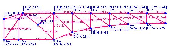
32 Roosevelt Rd. Bascule Truss Line Input Section Properties calculated in Excel, accounting for section loss as required Ag, An, Material, Ix, Iy, Sx, Sy Section Loss (if applicable) Live Load Distribution Factors Half Deck Line Locations Panel Point Loads

33 Roosevelt Rd. Bascule Trussed Floorbeams Moveable Span elements mostly rated in BrR Supplemental analysis independent of BrR for trussed floorbeams Floorbeam 2 2 Floorbeam Floorbeam 2 2 Floorbeam 10 10


34 Roosevelt Rd. Bascule Carrying Elements Fixed Span elements mostly rated in BrR Supplemental analysis required outside of BrR for some carrying elements Cross Girder (Trunnion Floorbeam) Stub Columns


35 Cermak Rd. Bascule Scherzer Rolling Lift Bascule Bridge


36 Cermak Rd. Bascule Bridge Lift
37 Cermak Rd. Bascule Original Construction Construction/Repair History 1906: Original Construction 1995: Majority of structure replaced as part of rehabilitation Truss top and bottom chords, verticals and diagonals Segmental and Track Girders Anchor Girder and Columns Bumping Girder Floorbeams and Stringers 1996: Deck replacement and rebalancing 1,064 existing plan sheets Design Load (Original) Design Load (1994 CDOT specifications) Geometry CL to CL First Positions of Roll 29 4 & ½ End Spans (each side)
38 Cermak Rd. Bascule Bascule Structure Components and Supports


39 Cermak Rd. Bascule Plan and Elevation

40 Cermak Rd. Bascule Cross Section
41 Cermak Rd. Bascule Load Stages BRIDGE OPEN Dead Load + Wind Load BRIDGE CLOSED Dead Load + Live Load (Including Pedestrian Load)


42 Cermak Rd. Bascule Dead Load Forces Dead Loads Truss member self weight Floorbeams Stringers Cantilever sidewalks Lateral Bracing Deck (Steel Grating) Counterweight Mechanical Housing


43 Cermak Rd. Bascule Dead Load Balancing 1906: Original Balancing 1996: Rebalancing 1996 Rebalancing Original Blocks

44 Cermak Rd. Bascule Carrying Elements Fixed Span roadway elements mostly rated in BrR Supplemental analysis required outside of BrR for some carrying elements Anchor Girder and Column Bumping Girder


45 Using BrR To Evaluate Bascule Bridges 2018 RADBUG MEETING BOISE, IDAHO AUGUST 7 8, 2018 Thank You! Questions?