District Five Concrete Pavement Update: 2010
|
|
|
- Sheena Miller
- 5 years ago
- Views:
Transcription
1 District Five Concrete Pavement Update: 2010 FTBA/FDOT Construction Conference Roger C. Schmitt, P.E. Orlando February 2010
2 Continuously Reinforced Concrete Pavement Constructed din 1968
3 I 95 Project Brevard County
4 I 95 Brevard County: Lessons Learned and Areas for Future Improved Items to be discussed: Concrete Thickness Stabilized Subgrade 1 inch Asphalt Layer Slag Mix Designs and Time to Saw Cut tjoints. Asphalt Treated Permeable Base Stripping Use of DBI: Dowel lbar Inserter Use of TBI: Tie Bar Inserter
5 I 95 Brevard County: Lessons Learned and Areas for Future Improvement Items to be discussed: Slab Removal and Replacement Drilling and Installing Dowel Bars Drilling and Installing Tie Bars

6 Design Typical Section New lanes were constructed of: 13 inches of PCC concrete 4 inches of asphalt treated permeable base drainage layer 1 inch layer of structural asphalt 12 inch stabilized subgrade. Existing lanes were constructed by: Mill existing asphalt to match concrete pavement grade 1 inch layer of structural asphalt 4 inch layer of asphalt treated permeable base drainage layer 13 inches of PCC concrete


7 Problem: Truck traffic on the newly constructed stabilized subgrade caused rutting and wheel marks as the subgrade dried out. Solution: The subgrade was brought to optimum moisture and primed. This preserved the moisture content and kept the rutting issue at a minimum. Contractors may want to use a graded aggregate to assist in firming up the stabilized subgrade.


8 Problem: One inch of structural asphalt over stabilized subgrade does not provide much support for subsequent operations Solution: The Department has changed its index to increase the thickness of the asphalt layer to 1 ½ inch.


9 Problem: Dowel bar insertion and maintaining proper alignment. Florida specifications prohibit the use of a dowel bar inserter. The Design build team included this method in their proposal with the condition that all joints would be scanned with a magnetic scanner to insure proper dowel alignment. The specification was strict and hard to meet. The design build team hired a consultant to study the joint movement. The study indicated that even moderate misalignment still allowed joint movement and the tolerances were reduced. District Five is writing a new specification to allow a joint score calculation which is recommended by the FHWA.
10 Dowel Placement Criteria


11 Problem: Establishing the correct time to green cut the transverse joints. The specification calls for the initial cut when the concrete was between 4 and 12 hours old. Solution: The concrete mix that is utilized is a 50% cement and 50% slag mix. This mix is slower to set than normal mixes. Trial batches were made and sent to the lab to establish initial and final set times, and this information as well as the saw cutter Forman's scratch test were used to determine the correct time. Initial saw cut times were around 24 hours. The Department will change their specifications for slag mixes.


12 Problem: Potential Asphalt Permeable Base Stripping. Solution: The Department cored several existing pavements with Asphalt Treated Permeable Base. The results indicated a majority of the existing projects had already stripping of the Asphalt Treated Permeable Base. Basedontheabsorptionoftheaggregatea greater % of Asphalt Binder was added to the Asphalt Treated Permeable Base that was equal to the absorption rate and in addition anti stripping additives were added to the mix.


13 Problem: Tie Bar inserter malfunction: During concrete pavement operations, the paving equipment placed two lanes per pass or a lane and a shoulder. The project specifications called for the lanes to have tie bars, number 5 bars at thirty inch spacing placed between lanes. The paving equipment malfunctioned and the bars were not inserted deep enough in many locations. Solution: Various repair procedures were investigated, but none were thought to match the projected lifespan of the concrete. The final solution was the replacement of over 1,000 slabs.


14 View of Several Slabs Removed


15 Over 1,000 Concrete Slabs Replaced


16 Replacement of Adjacent Slabs


17 Dowel Bar Installation Problems


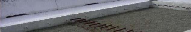
18 Tie Bar: Installation Problem
19 Conclusions: I 95 is a very Smooth Concrete Pavement Concrete Pavement Installation requires the Project Engineer and Inspector to pay attention to details. Dowel and Tie Bar Inserters need close attention and inspection during construction. Slab Replacement is not recommended for the Contractor or the Inspector.
20 Highways for Life: US 92 Florida First Seeding Mile of Concrete Pavement Lincoln Highway Malta, Illinois
21 Project Information Project will rehabilitate an existing 4 lane Divided Highway about 10 miles long. Approximately 10% of the slabs will be replaced. A mile section of the WB lanes will be completely reconstructed and the highway will be raised to avoid future flood water overtopping during heavy rainfall.
22 Project Information The1 1.7mile long Raised Section will consist of: Removal and crushing of the existing trapezoidal concrete section about 8 thick. The concrete will be recycled into a 8 thick graded aggregate base. Except in the Highways for Life section: the design calls for a 9 thick Jointed Concrete Pavement.
23 Project Information The Highways for Life Section will consist of a Precast Post Tensioned Concrete Panels about 9 ½ thick. The entire concrete pavement will be ground after slab replacement and pavement construction.
24 Relative Project Location


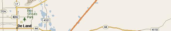
25 US 92 Project


26 Existing Concrete Pavement US 92 EB and WB Joints US 92 WB Highways for Life
27 US 92 Typical Joints West Bound Built in 1940, with 1 dowel bars. East Bound Built 1972 with Skewed Joints, but no dowel bars.
28 Slab Removal and Replacement
29 Finishing


30 Concrete Pavement Grinding Typical Grinding Equipment Before and After Grinding
31 Typical lfrom Texas Pilot Project


32 Precast Pavement Panels


33 Precast Pavement Panels
34 Highways for Life Details
35 Highways for Life Details
36 US 92 Details: 24 x 12 Panels
37 US 1 Pavement Performance: 21 Years after Construction
38 Edgewater, Florida
39 Project Information Location: US 1, South of Edgewater District 5 Length: 1.9 miles Type: Experimental Whitetopping (1.9 miles section of an 8 mile asphalt resurfacing project). Construction Completion: 1989 Traffic 2004: 14,000 AADT - 5% Trucks
40 JA1 Existing Conditions Prior to Whitetopping
41 Slide 40 JA1 the original asphalt suffered from significant cracking and some rutting> the FDOT decided to use whitetopping as an experimetal feature on 1.9 miles of the south bound of us 1. Jamshid Armaghani, 4/4/2005
42 JA2 US 1 Whitetopping Project 1999
43 Slide 41 JA2 This the US 1 south of Daytona beach Florida. It is the first whitetopping project in Florida and one of the very few early wt projects in the country. It was built between Jamshid Armaghani, 4/4/2005
44 US 1 Today
45 JA3 Standard 12 dowel pattern and tie bars
46 Slide 43 JA3 the standard dowle patern is shown here. the first dowel is 6" from the edge of the lane. all other dowels are spaced at 12" O/C. the tie bars were spaced at 3 ft o/c. Jamshid Armaghani, 4/4/2005


47 PCS Chart US 1 Southbound near PCC roadway
48 Initial Construction Costs for 1988 Based on the Bid Tab for Project provided po dedby the State Pavement Management Office. Only initial material costs were compared, since the overhead and MOT costs would be the same per lane mile. Initial Concrete costs weresignificantly ifi moreexpensive than a deep mill asphalt resurfacing. Over time the Whitetopping Project will be more cost effective than Multiple Mill and Resurface Rehabilitation. Let s look at the costs.
49 Project Costs to Date Project Cost Analysis PCC versus Asphalt Initial Construction in 1988 Figures from Plans " PCC Asphalt Description Unit Amount Cost Cost/Mile Description Unit Amount Cost Cost/Mile Mill 4.5 Inches SY Mill 4.5 Inches SY PCC 6 inches SY inches Type S TN inch Type S TN /8 inch of FC 2 SY Total Tack GA Total " PCC 8" PCC Description Unit Amount Cost Cost/Mile Description Unit Amount Cost Cost/Mile Mill 4.5 Inches SY Mill 4 Inches SY PCC 7 inches SY PCC 8 inches SY inch Type S TN inch Type S TN Total Total PCC/Asp Cost Per Year Difference Cul. Total* PCC Asphalt Difference Diff. (%) " % " % " %
50 First Concrete Rehab: 2010 Asphalt Cost/Mile is Still More oecost Effective e PCC/Asp Cost Per Year Difference PCC Slab Repair in 2010 Slab Repair in 2009 Flating Average's Used Cul. Total* Cost/Year PCC Asphalt Difference Diff. (%) Description Unit Amount Cost Cost/Mile " % PCC 6 inches CY " % PCC 8 inches CY " % Design EA LS * Total PCC Cost In House Inspection EA LS Asphalt MOB, MOT, Other EA LS Cul. Total* Cost/Yr Cul. Total Cost/Yr Total Total Slabs Replaced: 6 (3 6 inch & 3 8 inch ) * Total Asphalt Cost /2 of 1 percent of all slabs (1262 total) ESAL Life Estimate PCC ASPHALT ,910, , PCC EF/LF Factors From Rigid Design Manual Asphalt hl EF/LF Factors from Flexible Design Manual
51 First Mill and Resurface 2002 Asphalt Cost/Mile is Still Cost Effective First Resurface in 2002 PCC/Asp Cost Per Year Difference Figures from Plans to Cul. Total* Cost/Year PCC Asphalt Difference Diff. (%) Description Unit Amount Cost Cost/Mile " % Design EA 1 LM " % In House Inspection EA 1 LM " % 39% Tack GA ESAL Life Estimate Milling 2 inches SY PCC ASPHALT MOB, MOT, Other EA 1 LM , , Cul. Total* Cost/Yr Total PCC EF/LF Factors From Rigid Design Manual , Asphalt EF/LF Factors from Flexible Design Manual * Total Asphalt Cost
52 Second Mill and Resurface:2013 Whitetopping Cost/Mile is more Cost Effective e Second Resurface in 2013 PCC/Asp Cost Per Year Difference ee 2009 Floating Averages Used Cul. Total* Cost/Year PCC Asphalt Difference Diff. (%) Description Unit Amount Cost Cost/Mile " % In House Design EA LS " % In House Inspection EA 1 LM " %.75 inch FC 5 TN * Total PCC Cost inches TL D TN Milling 3 inches SY ESAL Life Estimate MOB, MOT, Other EA 1 LM PCC ASPHALT Cul. Total* Cost/Yr Total ,416, , PCC EF/LF Factors From Rigid Design Manual * Total Asphalt Cost Asphalt EF/LF Factors from Flexible Design Manual Tack costs for 2013 and 2028 included with asphalt
53 3% Slab Replacement and Third Resurfacing: 2024 Whitetopping Cost/Mile is morecost Effective Third Resurface in % Slab Replacement 2009 Floating Averages Used LM=3.716 Third Resurface in Floating Averages Used Slabs Length Width Depth CY's All Cost Description Unit Amount Cost Cost/Mile In House Design EA LS Description Unit Amount Cost Cost/Mile In House Inspection EA 1 LM In House Inspection EA 1 LM inch FC 5 TN In House Design EA LS inches TL D TN Slab Replacement CY Milling 3 inches SY Seal Joints LF MOB, MOT, Other EA 1 LM Diamond Grind SY Cul. Total* Cost/Yr Total MOB, MOT, Other EA 1 LM Total * Total Asphalt hlcost PCC/Asp Cost Per Year Difference Tack costs for 2013 and 2028 included with asphalt Cul. Total* Cost/Year PCC Asphalt Difference Diff. (%) ESAL Life Estimate " % PCC ASPHALT " % ,067,000 1,134, " % 73% PCCEF/LF Factors FromRigid Design Manual * Total PCC Cost Asphalt EF/LF Factors from Flexible Design Manual
54 In Case You Were Wondering? Bryce Canyon Utah
55 Any Questions